engine SUBARU TRIBECA 2009 1.G Service Workshop Manual
[x] Cancel search | Manufacturer: SUBARU, Model Year: 2009, Model line: TRIBECA, Model: SUBARU TRIBECA 2009 1.GPages: 2453, PDF Size: 46.32 MB
Page 1983 of 2453
SC(H6DO)-25
Battery
STARTING/CHARGING SYSTEMS
4. Battery
A: REMOVAL
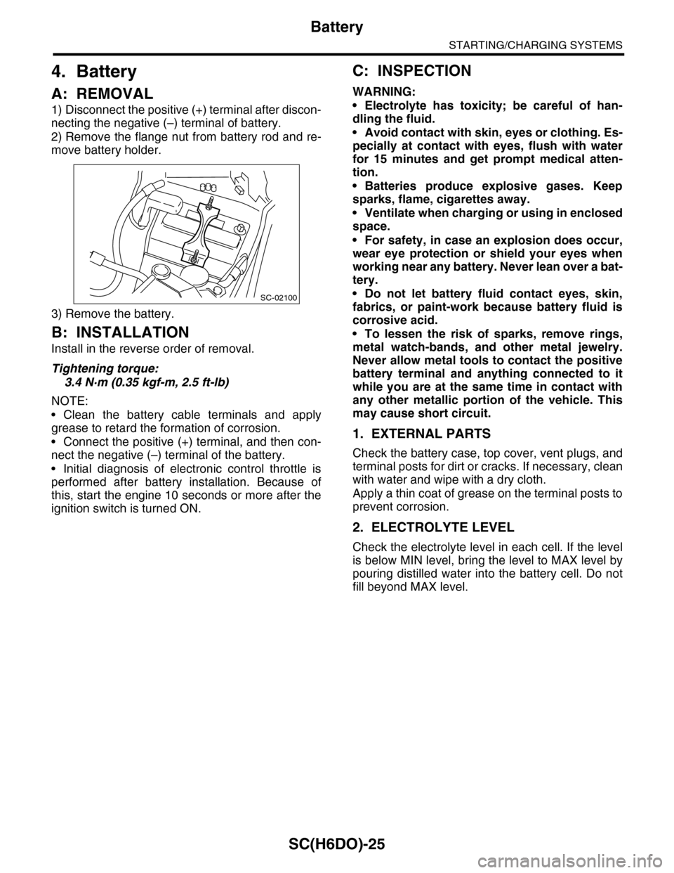
1) Disconnect the positive (+) terminal after discon-
necting the negative (–) terminal of battery.
2) Remove the flange nut from battery rod and re-
move battery holder.
3) Remove the battery.
B: INSTALLATION
Install in the reverse order of removal.
Tightening torque:
3.4 N·m (0.35 kgf-m, 2.5 ft-lb)
NOTE:
•Clean the battery cable terminals and apply
grease to retard the formation of corrosion.
•Connect the positive (+) terminal, and then con-
nect the negative (–) terminal of the battery.
•Initial diagnosis of electronic control throttle is
performed after battery installation. Because of
this, start the engine 10 seconds or more after the
ignition switch is turned ON.
C: INSPECTION
WARNING:
•Electrolyte has toxicity; be careful of han-
dling the fluid.
•Avoid contact with skin, eyes or clothing. Es-
pecially at contact with eyes, flush with water
for 15 minutes and get prompt medical atten-
tion.
•Batteries produce explosive gases. Keep
sparks, flame, cigarettes away.
•Ventilate when charging or using in enclosed
space.
•For safety, in case an explosion does occur,
wear eye protection or shield your eyes when
working near any battery. Never lean over a bat-
tery.
•Do not let battery fluid contact eyes, skin,
fabrics, or paint-work because battery fluid is
corrosive acid.
•To lessen the risk of sparks, remove rings,
metal watch-bands, and other metal jewelry.
Never allow metal tools to contact the positive
battery terminal and anything connected to it
while you are at the same time in contact with
any other metallic portion of the vehicle. This
may cause short circuit.
1. EXTERNAL PARTS
Check the battery case, top cover, vent plugs, and
terminal posts for dirt or cracks. If necessary, clean
with water and wipe with a dry cloth.
Apply a thin coat of grease on the terminal posts to
prevent corrosion.
2. ELECTROLYTE LEVEL
Check the electrolyte level in each cell. If the level
is below MIN level, bring the level to MAX level by
pouring distilled water into the battery cell. Do not
fill beyond MAX level.
SC-02100
Page 1986 of 2453
PM-3
Schedule
PERIODIC MAINTENANCE SERVICES
2. Schedule
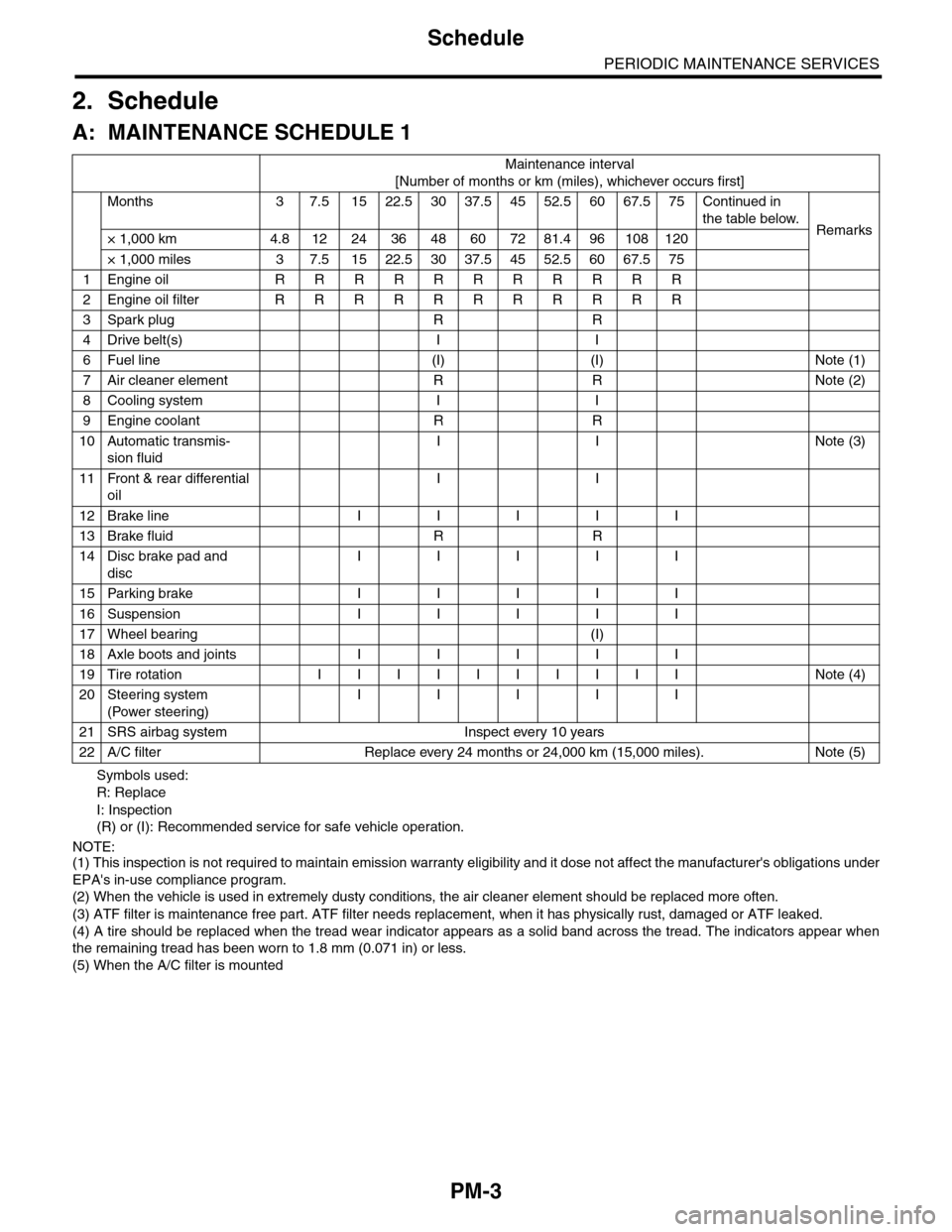
A: MAINTENANCE SCHEDULE 1
Symbols used:
R: Replace
I: Inspection
(R) or (I): Recommended service for safe vehicle operation.
NOTE:(1) This inspection is not required to maintain emission warranty eligibility and it dose not affect the manufacturer's obligations under
EPA's in-use compliance program.
(2) When the vehicle is used in extremely dusty conditions, the air cleaner element should be replaced more often.
(3) ATF filter is maintenance free part. ATF filter needs replacement, when it has physically rust, damaged or ATF leaked.
(4) A tire should be replaced when the tread wear indicator appears as a solid band across the tread. The indicators appear when
the remaining tread has been worn to 1.8 mm (0.071 in) or less.
(5) When the A/C filter is mounted
Maintenance interval
[Number of months or km (miles), whichever occurs first]
Months 3 7.51522.53037.54552.56067.575Continued in
the table below.Remarks× 1,000 km 4.8 12 24 36 48 60 72 81.4 96 108 120
× 1,000 miles 3 7.5 15 22.5 30 37.5 45 52.5 60 67.5 75
1Engine oil R R R R R R R R R R R
2Engine oil filter R R R R R R R R R R R
3Spark plug R R
4Drive belt(s) I I
6Fuel line (I) (I) Note (1)
7Air cleaner element R R Note (2)
8Cooling system I I
9Engine coolant R R
10 Automatic transmis-
sion fluid
I I Note (3)
11 Front & rear differential
oil
I I
12 Brake line I I I I I
13 Brake fluid R R
14 Disc brake pad and
disc
I I I I I
15 Parking brake I I I I I
16 Suspension I I I I I
17 Wheel bearing (I)
18 Axle boots and joints I I I I I
19 Tire rotation I I I I I I I I I I Note (4)
20 Steering system
(Power steering)
I I I I I
21 SRS airbag system Inspect every 10 years
22 A/C filter Replace every 24 months or 24,000 km (15,000 miles). Note (5)
Page 1987 of 2453
PM-4
Schedule
PERIODIC MAINTENANCE SERVICES
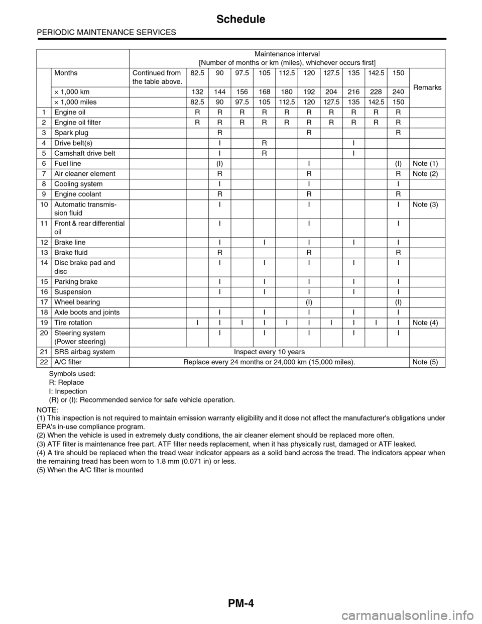
Symbols used:
R: Replace
I: Inspection
(R) or (I): Recommended service for safe vehicle operation.
NOTE:(1) This inspection is not required to maintain emission warranty eligibility and it dose not affect the manufacturer's obligations under
EPA's in-use compliance program.
(2) When the vehicle is used in extremely dusty conditions, the air cleaner element should be replaced more often.
(3) ATF filter is maintenance free part. ATF filter needs replacement, when it has physically rust, damaged or ATF leaked.
(4) A tire should be replaced when the tread wear indicator appears as a solid band across the tread. The indicators appear when
the remaining tread has been worn to 1.8 mm (0.071 in) or less.
(5) When the A/C filter is mounted
Maintenance interval
[Number of months or km (miles), whichever occurs first]
Months Continued from
the table above.
82.5 90 97.5 105112.5120127.5135142.5150
Remarks× 1,000 km 132 144 156 168 180 192 204 216 228 240
× 1,000 miles 82.5 90 97.5 105112.5120127.5135142.5150
1Engine oil R R R R R R R R R R
2Engine oil filter R R R R R R R R R R
3Spark plug R R R
4Drive belt(s) I R I
5Camshaft drive belt I R I
6Fuel line (I) I (I) Note (1)
7Air cleaner element R R R Note (2)
8Cooling system I I I
9Engine coolant R R R
10 Automatic transmis-
sion fluid
I I INote (3)
11 Front & rear differential
oil
I I I
12 Brake line I I I I I
13 Brake fluid R R R
14 Disc brake pad and
disc
I I I I I
15 Parking brake I I I I I
16 Suspension I I I I I
17 Wheel bearing (I) (I)
18 Axle boots and joints I I I I I
19 Tire rotation I I I I I I I I I I Note (4)
20 Steering system
(Power steering)
I I I I I
21 SRS airbag system Inspect every 10 years
22 A/C filter Replace every 24 months or 24,000 km (15,000 miles). Note (5)
Page 1988 of 2453
PM-5
Schedule
PERIODIC MAINTENANCE SERVICES
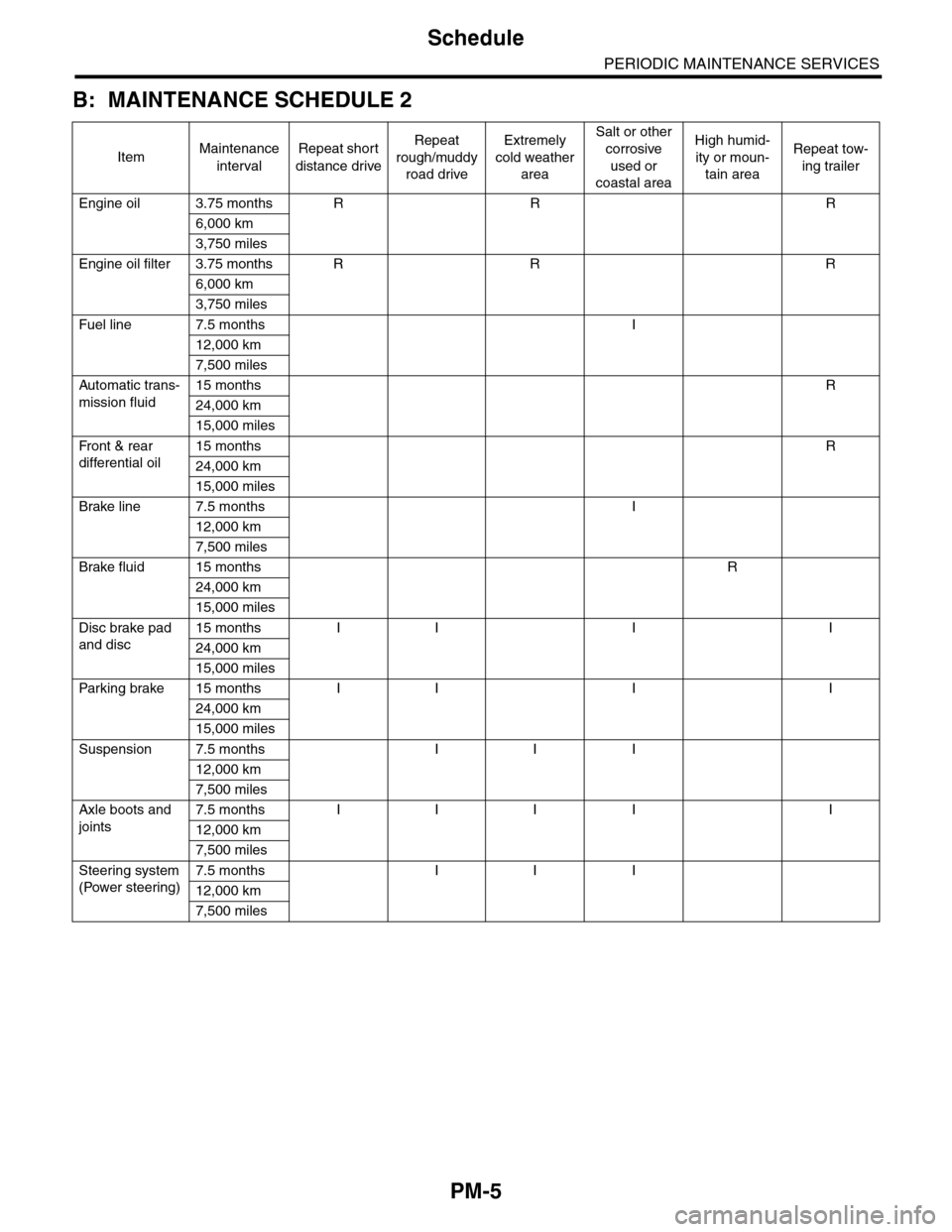
B: MAINTENANCE SCHEDULE 2
ItemMaintenance
interval
Repeat short
distance drive
Repeat
rough/muddy
road drive
Extremely
cold weather
area
Salt or other
corrosive
used or
coastal area
High humid-
ity or moun-
tain area
Repeat tow-
ing trailer
Engine oil 3.75 months R R R
6,000 km
3,750 miles
Engine oil filter 3.75 months R R R
6,000 km
3,750 miles
Fuel line 7.5 months I
12,000 km
7,500 miles
Automatic trans-
mission fluid
15 months R
24,000 km
15,000 miles
Fr o nt & r ea r
differential oil
15 months R
24,000 km
15,000 miles
Brake line 7.5 months I
12,000 km
7,500 miles
Brake fluid 15 months R
24,000 km
15,000 miles
Disc brake pad
and disc
15 months I I I I
24,000 km
15,000 miles
Par king brake 15 months I I I I
24,000 km
15,000 miles
Suspension 7.5 months I I I
12,000 km
7,500 miles
Axle boots and
joints
7.5 months I I I I I
12,000 km
7,500 miles
Steering system
(Power steering)
7.5 months I I I
12,000 km
7,500 miles
Page 1989 of 2453
PM-6
Engine Oil
PERIODIC MAINTENANCE SERVICES
3. Engine Oil
A: REPLACEMENT
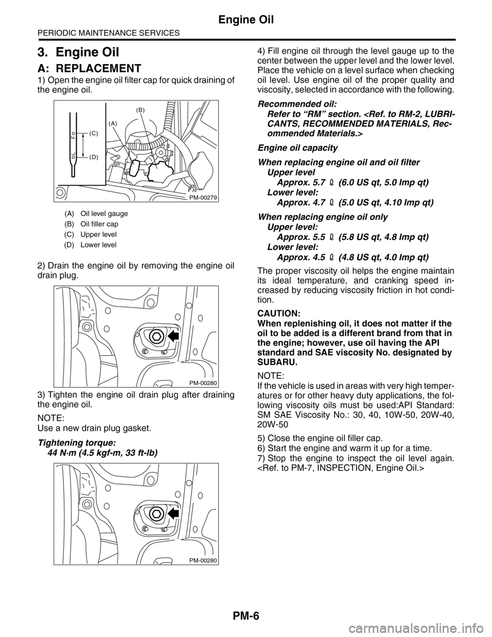
1) Open the engine oil filter cap for quick draining of
the engine oil.
2) Drain the engine oil by removing the engine oil
drain plug.
3) Tighten the engine oil drain plug after draining
the engine oil.
NOTE:
Use a new drain plug gasket.
Tightening torque:
44 N·m (4.5 kgf-m, 33 ft-lb)
4) Fill engine oil through the level gauge up to the
center between the upper level and the lower level.
Place the vehicle on a level surface when checking
oil level. Use engine oil of the proper quality and
viscosity, selected in accordance with the following.
Recommended oil:
Refer to “RM” section.
ommended Materials.>
Engine oil capacity
When replacing engine oil and oil filter
Upper level
Approx. 5.7 2 (6.0 US qt, 5.0 Imp qt)
Lower level:
Approx. 4.7 2 (5.0 US qt, 4.10 Imp qt)
When replacing engine oil only
Upper level:
Approx. 5.5 2 (5.8 US qt, 4.8 Imp qt)
Lower level:
Approx. 4.5 2 (4.8 US qt, 4.0 Imp qt)
The proper viscosity oil helps the engine maintain
its ideal temperature, and cranking speed in-
creased by reducing viscosity friction in hot condi-
tion.
CAUTION:
When replenishing oil, it does not matter if the
oil to be added is a different brand from that in
the engine; however, use oil having the API
standard and SAE viscosity No. designated by
SUBARU.
NOTE:
If the vehicle is used in areas with very high temper-
atures or for other heavy duty applications, the fol-
lowing viscosity oils must be used:API Standard:
SM SAE Viscosity No.: 30, 40, 10W-50, 20W-40,
20W-50
5) Close the engine oil filler cap.
6) Start the engine and warm it up for a time.
7) Stop the engine to inspect the oil level again.
(A) Oil level gauge
(B) Oil filler cap
(C) Upper level
(D) Lower level
PM-00279
(A)
(B)
(C)
(D)
PM-00280
PM-00280
Page 1990 of 2453
PM-7
Engine Oil
PERIODIC MAINTENANCE SERVICES
B: INSPECTION
1) Park the vehicle on a level surface.
2) Remove the oil level gauge and wipe it clean.
3) Reinsert the level gauge all the way. Be sure that
the level gauge is correctly inserted and in the
proper orientation.
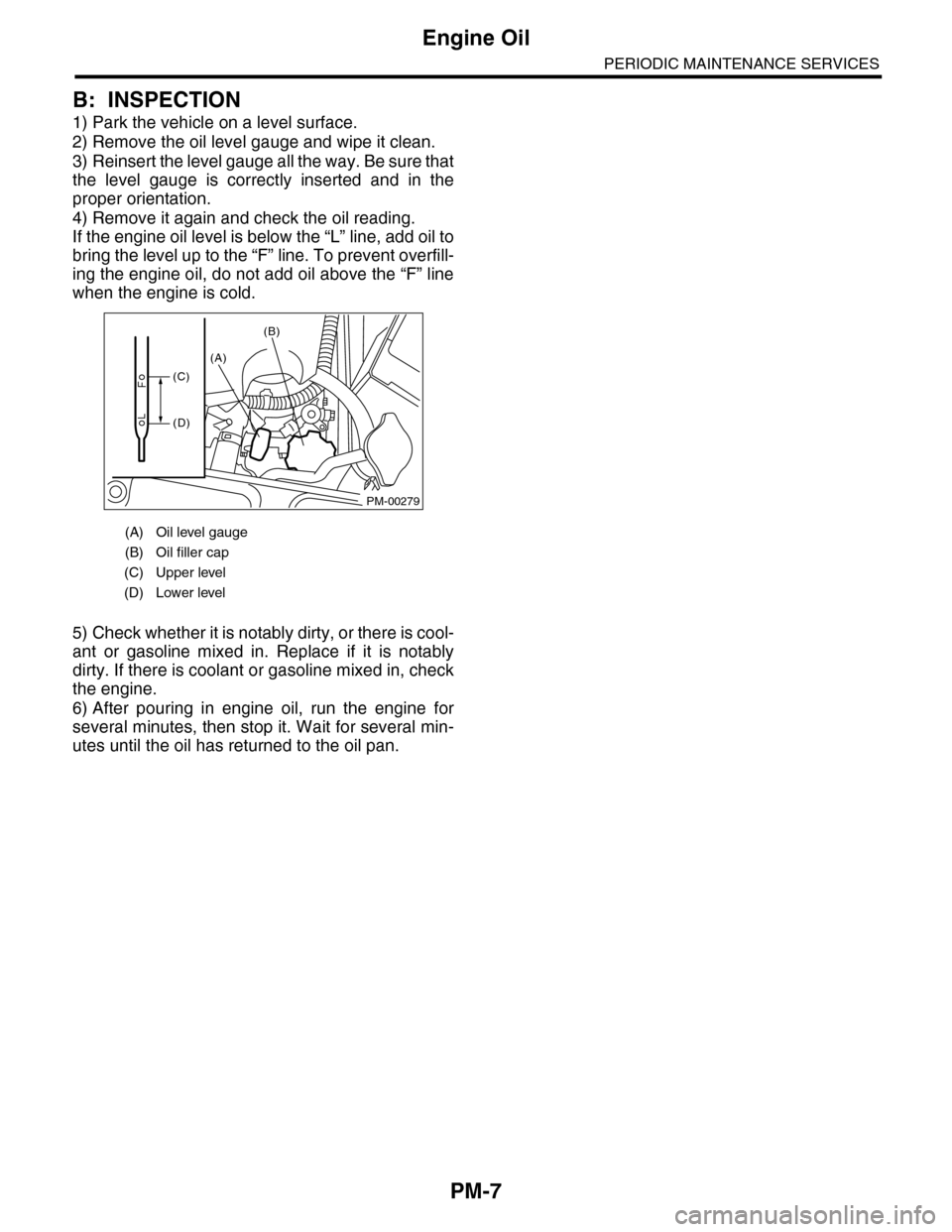
4) Remove it again and check the oil reading.
If the engine oil level is below the “L” line, add oil to
bring the level up to the “F” line. To prevent overfill-
ing the engine oil, do not add oil above the “F” line
when the engine is cold.
5) Check whether it is notably dirty, or there is cool-
ant or gasoline mixed in. Replace if it is notably
dirty. If there is coolant or gasoline mixed in, check
the engine.
6) After pouring in engine oil, run the engine for
several minutes, then stop it. Wait for several min-
utes until the oil has returned to the oil pan.
(A) Oil level gauge
(B) Oil filler cap
(C) Upper level
(D) Lower level
PM-00279
(A)
(B)
(C)
(D)
Page 1991 of 2453
PM-8
Engine Oil Filter
PERIODIC MAINTENANCE SERVICES
4. Engine Oil Filter
A: REPLACEMENT
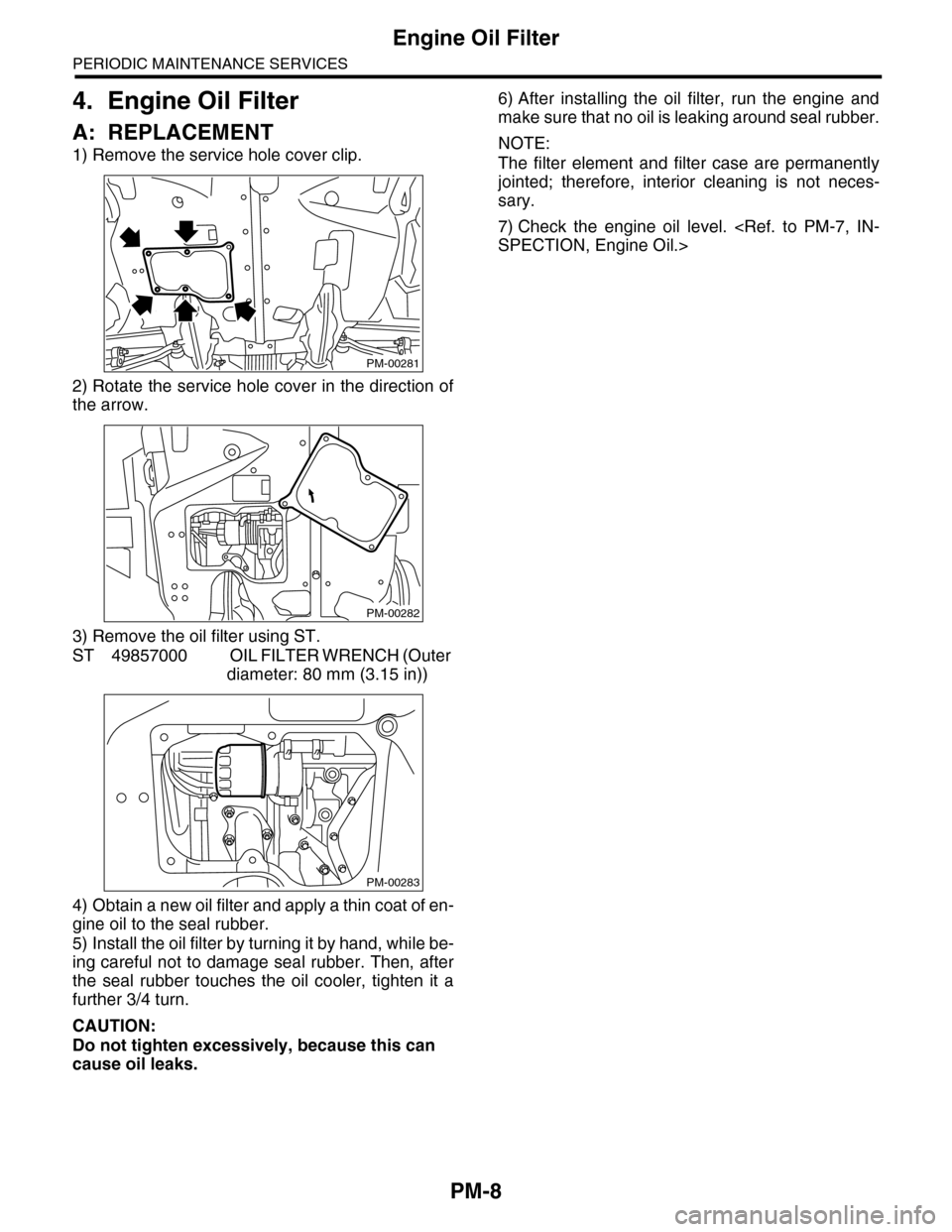
1) Remove the service hole cover clip.
2) Rotate the service hole cover in the direction of
the arrow.
3) Remove the oil filter using ST.
ST 49857000 OIL FILTER WRENCH (Outer
diameter: 80 mm (3.15 in))
4) Obtain a new oil filter and apply a thin coat of en-
gine oil to the seal rubber.
5) Install the oil filter by turning it by hand, while be-
ing careful not to damage seal rubber. Then, after
the seal rubber touches the oil cooler, tighten it a
further 3/4 turn.
CAUTION:
Do not tighten excessively, because this can
cause oil leaks.
6) After installing the oil filter, run the engine and
make sure that no oil is leaking around seal rubber.
NOTE:
The filter element and filter case are permanently
jointed; therefore, interior cleaning is not neces-
sary.
7) Check the engine oil level.
PM-00281
PM-00282
PM-00283
Page 1994 of 2453
PM-11
Fuel Line
PERIODIC MAINTENANCE SERVICES
7. Fuel Line
A: INSPECTION
The fuel line is located mostly internally, so check
pipes, areas near pipes, and engine compartment
piping for rust, hose damage, loose band, etc. If
faulty parts are found, repair or replace them.
oration Lines.>
Page 1996 of 2453
PM-13
Cooling System
PERIODIC MAINTENANCE SERVICES
9. Cooling System
A: INSPECTION
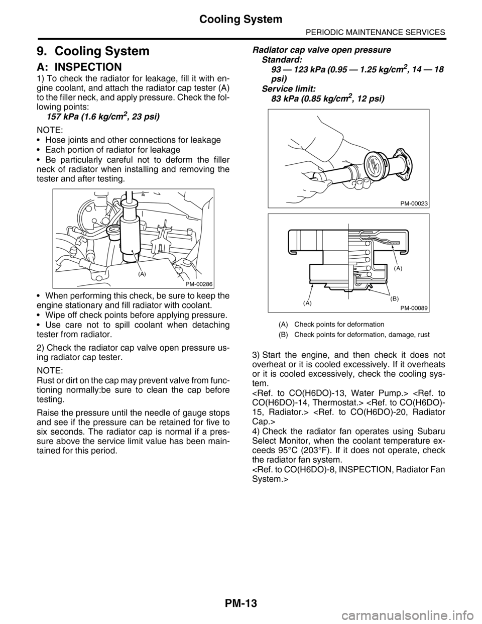
1) To check the radiator for leakage, fill it with en-
gine coolant, and attach the radiator cap tester (A)
to the filler neck, and apply pressure. Check the fol-
lowing points:
157 kPa (1.6 kg/cm2, 23 psi)
NOTE:
•Hose joints and other connections for leakage
•Each portion of radiator for leakage
•Be particularly careful not to deform the filler
neck of radiator when installing and removing the
tester and after testing.
•When performing this check, be sure to keep the
engine stationary and fill radiator with coolant.
•Wipe off check points before applying pressure.
•Use care not to spill coolant when detaching
tester from radiator.
2) Check the radiator cap valve open pressure us-
ing radiator cap tester.
NOTE:
Rust or dirt on the cap may prevent valve from func-
tioning normally:be sure to clean the cap before
testing.
Raise the pressure until the needle of gauge stops
and see if the pressure can be retained for five to
six seconds. The radiator cap is normal if a pres-
sure above the service limit value has been main-
tained for this period.
Radiator cap valve open pressure
Standard:
93 — 123 kPa (0.95 — 1.25 kg/cm2, 14 — 18
psi)
Service limit:
83 kPa (0.85 kg/cm2, 12 psi)
3) Start the engine, and then check it does not
overheat or it is cooled excessively. If it overheats
or it is cooled excessively, check the cooling sys-
tem.
4) Check the radiator fan operates using Subaru
Select Monitor, when the coolant temperature ex-
ceeds 95°C (203°F). If it does not operate, check
the radiator fan system.
PM-00286
(A)
(A) Check points for deformation
(B) Check points for deformation, damage, rust
PM-00023
PM-00089
(B)(A)
(A)
Page 1997 of 2453
PM-14
Engine Coolant
PERIODIC MAINTENANCE SERVICES
10.Engine Coolant
A: REPLACEMENT
1. REPLACEMENT OF ENGINE COOLANT
WARNING:
The radiator is of the pressurized type. Do not
attempt to open the radiator cap immediately
after the engine has been stopped.
1) Lift-up the vehicle.
2) Remove the under cover.
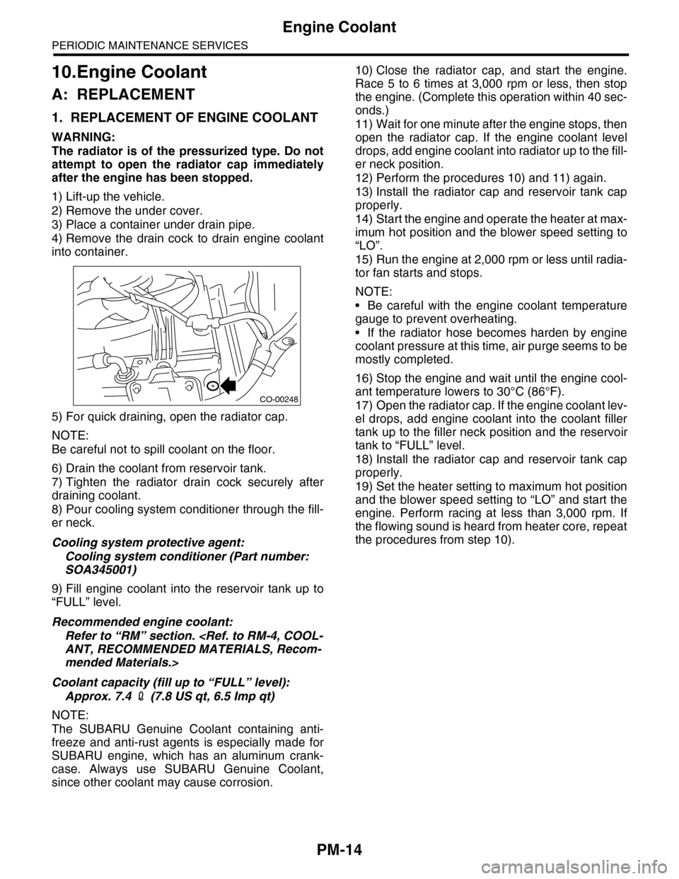
3) Place a container under drain pipe.
4) Remove the drain cock to drain engine coolant
into container.
5) For quick draining, open the radiator cap.
NOTE:
Be careful not to spill coolant on the floor.
6) Drain the coolant from reservoir tank.
7) Tighten the radiator drain cock securely after
draining coolant.
8) Pour cooling system conditioner through the fill-
er neck.
Cooling system protective agent:
Cooling system conditioner (Part number:
SOA345001)
9) Fill engine coolant into the reservoir tank up to
“FULL” level.
Recommended engine coolant:
Refer to “RM” section.
mended Materials.>
Coolant capacity (fill up to “FULL” level):
Approx. 7.4 2 (7.8 US qt, 6.5 Imp qt)
NOTE:
The SUBARU Genuine Coolant containing anti-
freeze and anti-rust agents is especially made for
SUBARU engine, which has an aluminum crank-
case. Always use SUBARU Genuine Coolant,
since other coolant may cause corrosion.
10) Close the radiator cap, and start the engine.
Race 5 to 6 times at 3,000 rpm or less, then stop
the engine. (Complete this operation within 40 sec-
onds.)
11) Wait for one minute after the engine stops, then
open the radiator cap. If the engine coolant level
drops, add engine coolant into radiator up to the fill-
er neck position.
12) Perform the procedures 10) and 11) again.
13) Install the radiator cap and reservoir tank cap
properly.
14) Start the engine and operate the heater at max-
imum hot position and the blower speed setting to
“LO”.
15) Run the engine at 2,000 rpm or less until radia-
tor fan starts and stops.
NOTE:
•Be careful with the engine coolant temperature
gauge to prevent overheating.
•If the radiator hose becomes harden by engine
coolant pressure at this time, air purge seems to be
mostly completed.
16) Stop the engine and wait until the engine cool-
ant temperature lowers to 30°C (86°F).
17) Open the radiator cap. If the engine coolant lev-
el drops, add engine coolant into the coolant filler
tank up to the filler neck position and the reservoir
tank to “FULL” level.
18) Install the radiator cap and reservoir tank cap
properly.
19) Set the heater setting to maximum hot position
and the blower speed setting to “LO” and start the
engine. Perform racing at less than 3,000 rpm. If
the flowing sound is heard from heater core, repeat
the procedures from step 10).
CO-00248