engine SUBARU TRIBECA 2009 1.G Service Workshop Manual
[x] Cancel search | Manufacturer: SUBARU, Model Year: 2009, Model line: TRIBECA, Model: SUBARU TRIBECA 2009 1.GPages: 2453, PDF Size: 46.32 MB
Page 2144 of 2453
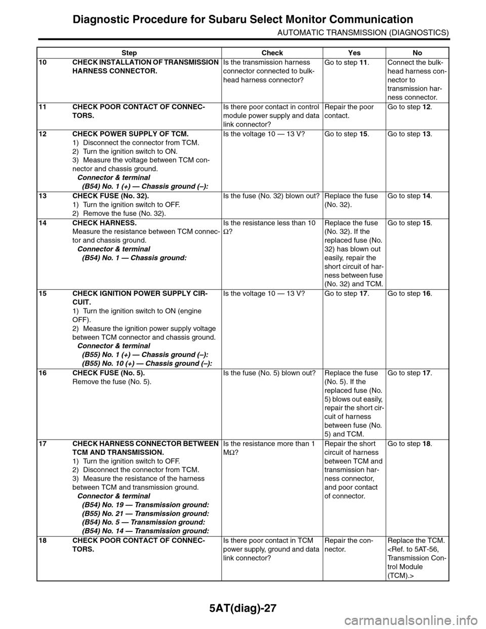
5AT(diag)-27
Diagnostic Procedure for Subaru Select Monitor Communication
AUTOMATIC TRANSMISSION (DIAGNOSTICS)
10 CHECK INSTALLATION OF TRANSMISSION
HARNESS CONNECTOR.
Is the transmission harness
connector connected to bulk-
head harness connector?
Go to step 11.Connect the bulk-
head harness con-
nector to
transmission har-
ness connector.
11 CHECK POOR CONTACT OF CONNEC-
TORS.
Is there poor contact in control
module power supply and data
link connector?
Repair the poor
contact.
Go to step 12.
12 CHECK POWER SUPPLY OF TCM.
1) Disconnect the connector from TCM.
2) Turn the ignition switch to ON.
3) Measure the voltage between TCM con-
nector and chassis ground.
Connector & terminal
(B54) No. 1 (+) — Chassis ground (–):
Is the voltage 10 — 13 V? Go to step 15.Go to step 13.
13 CHECK FUSE (No. 32).
1) Turn the ignition switch to OFF.
2) Remove the fuse (No. 32).
Is the fuse (No. 32) blown out? Replace the fuse
(No. 32).
Go to step 14.
14 CHECK HARNESS.
Measure the resistance between TCM connec-
tor and chassis ground.
Connector & terminal
(B54) No. 1 — Chassis ground:
Is the resistance less than 10
Ω?
Replace the fuse
(No. 32). If the
replaced fuse (No.
32) has blown out
easily, repair the
short circuit of har-
ness between fuse
(No. 32) and TCM.
Go to step 15.
15 CHECK IGNITION POWER SUPPLY CIR-
CUIT.
1) Turn the ignition switch to ON (engine
OFF).
2) Measure the ignition power supply voltage
between TCM connector and chassis ground.
Connector & terminal
(B55) No. 1 (+) — Chassis ground (–):
(B55) No. 10 (+) — Chassis ground (–):
Is the voltage 10 — 13 V? Go to step 17.Go to step 16.
16 CHECK FUSE (No. 5).
Remove the fuse (No. 5).
Is the fuse (No. 5) blown out? Replace the fuse
(No. 5). If the
replaced fuse (No.
5) blows out easily,
repair the short cir-
cuit of harness
between fuse (No.
5) and TCM.
Go to step 17.
17 CHECK HARNESS CONNECTOR BETWEEN
TCM AND TRANSMISSION.
1) Turn the ignition switch to OFF.
2) Disconnect the connector from TCM.
3) Measure the resistance of the harness
between TCM and transmission ground.
Connector & terminal
(B54) No. 19 — Transmission ground:
(B55) No. 21 — Transmission ground:
(B54) No. 5 — Transmission ground:
(B54) No. 14 — Transmission ground:
Is the resistance more than 1
MΩ?
Repair the short
circuit of harness
between TCM and
transmission har-
ness connector,
and poor contact
of connector.
Go to step 18.
18 CHECK POOR CONTACT OF CONNEC-
TORS.
Is there poor contact in TCM
power supply, ground and data
link connector?
Repair the con-
nector.
Replace the TCM.
trol Module
(TCM).>
Step Check Yes No
Page 2145 of 2453
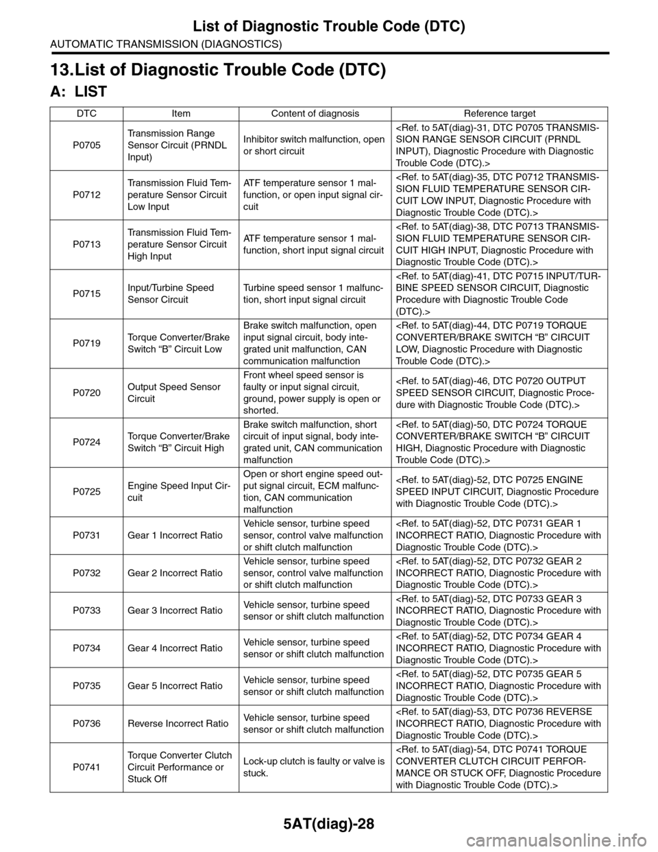
5AT(diag)-28
List of Diagnostic Trouble Code (DTC)
AUTOMATIC TRANSMISSION (DIAGNOSTICS)
13.List of Diagnostic Trouble Code (DTC)
A: LIST
DTC Item Content of diagnosis Reference target
P0705
Tr a n s m i s s i o n R a n g e
Sensor Circuit (PRNDL
Input)
Inhibitor switch malfunction, open
or short circuit
INPUT), Diagnostic Procedure with Diagnostic
Tr o u b l e C o d e ( D T C ) . >
P0712
Tr a n s m i s s i o n F l u i d Te m -
perature Sensor Circuit
Low Input
AT F t e m p e r a t u r e s e n s o r 1 m a l -
function, or open input signal cir-
cuit
CUIT LOW INPUT, Diagnostic Procedure with
Diagnostic Trouble Code (DTC).>
P0713
Tr a n s m i s s i o n F l u i d Te m -
perature Sensor Circuit
High Input
AT F t e m p e r a t u r e s e n s o r 1 m a l -
function, short input signal circuit
CUIT HIGH INPUT, Diagnostic Procedure with
Diagnostic Trouble Code (DTC).>
P0715Input/Turbine Speed
Sensor Circuit
Tu r b i n e s p e e d s e n s o r 1 m a l f u n c -
tion, short input signal circuit
Procedure with Diagnostic Trouble Code
(DTC).>
P0719To r q u e C o n v e r t e r / B r a k e
Switch “B” Circuit Low
Brake switch malfunction, open
input signal circuit, body inte-
grated unit malfunction, CAN
communication malfunction
LOW, Diagnostic Procedure with Diagnostic
Tr o u b l e C o d e ( D T C ) . >
P0720Output Speed Sensor
Circuit
Front wheel speed sensor is
faulty or input signal circuit,
ground, power supply is open or
shorted.
dure with Diagnostic Trouble Code (DTC).>
P0724To r q u e C o n v e r t e r / B r a k e
Switch “B” Circuit High
Brake switch malfunction, short
circuit of input signal, body inte-
grated unit, CAN communication
malfunction
HIGH, Diagnostic Procedure with Diagnostic
Tr o u b l e C o d e ( D T C ) . >
P0725Engine Speed Input Cir-
cuit
Open or short engine speed out-
put signal circuit, ECM malfunc-
tion, CAN communication
malfunction
with Diagnostic Trouble Code (DTC).>
P0731 Gear 1 Incorrect Ratio
Ve h i c l e s e n s o r, t u r b i n e s p e e d
sensor, control valve malfunction
or shift clutch malfunction
Diagnostic Trouble Code (DTC).>
P0732 Gear 2 Incorrect Ratio
Ve h i c l e s e n s o r, t u r b i n e s p e e d
sensor, control valve malfunction
or shift clutch malfunction
Diagnostic Trouble Code (DTC).>
P0733 Gear 3 Incorrect RatioVe h i c l e s e n s o r, t u r b i n e s p e e d
sensor or shift clutch malfunction
Diagnostic Trouble Code (DTC).>
P0734 Gear 4 Incorrect RatioVe h i c l e s e n s o r, t u r b i n e s p e e d
sensor or shift clutch malfunction
Diagnostic Trouble Code (DTC).>
P0735 Gear 5 Incorrect RatioVe h i c l e s e n s o r, t u r b i n e s p e e d
sensor or shift clutch malfunction
Diagnostic Trouble Code (DTC).>
P0736 Reverse Incorrect RatioVe h i c l e s e n s o r, t u r b i n e s p e e d
sensor or shift clutch malfunction
Diagnostic Trouble Code (DTC).>
P0741
To r q u e C o n v e r t e r C l u t c h
Circuit Performance or
Stuck Off
Lock-up clutch is faulty or valve is
stuck.
MANCE OR STUCK OFF, Diagnostic Procedure
with Diagnostic Trouble Code (DTC).>
Page 2147 of 2453
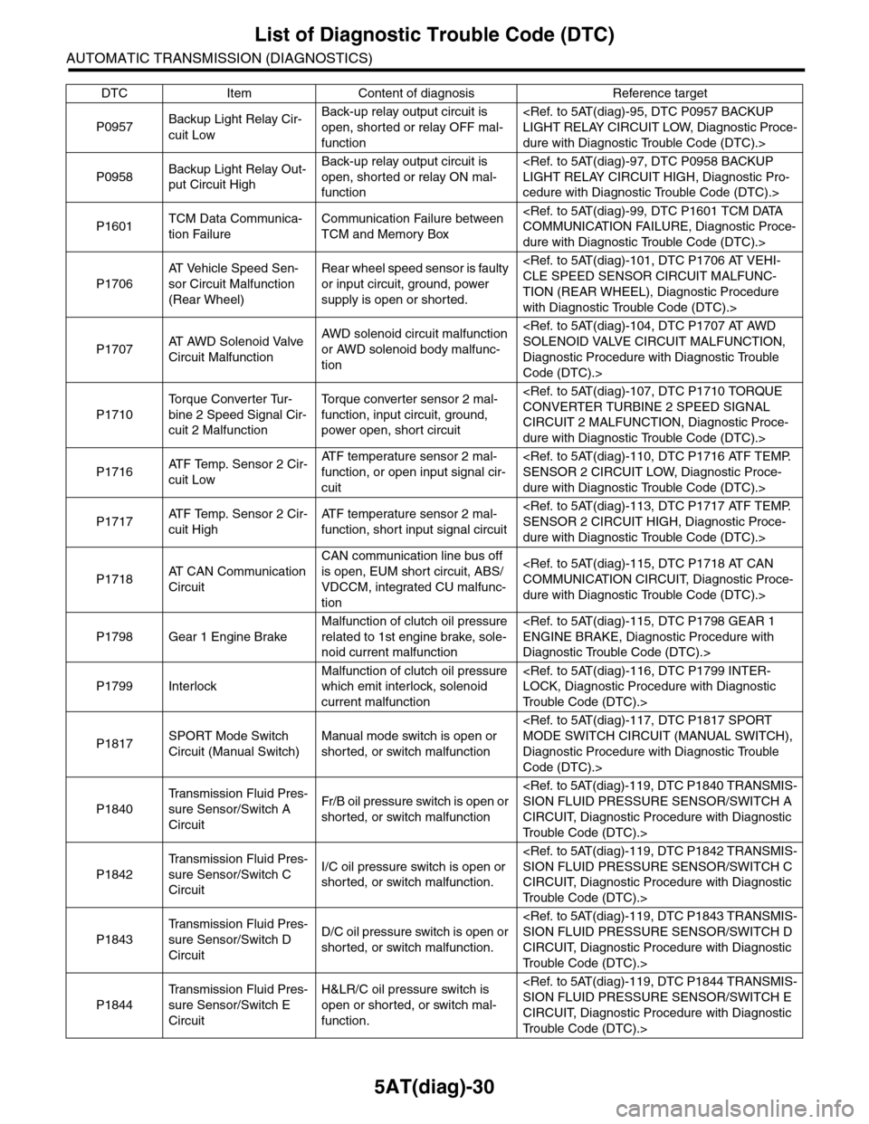
5AT(diag)-30
List of Diagnostic Trouble Code (DTC)
AUTOMATIC TRANSMISSION (DIAGNOSTICS)
P0957Backup Light Relay Cir-
cuit Low
Back-up relay output circuit is
open, shorted or relay OFF mal-
function
dure with Diagnostic Trouble Code (DTC).>
P0958Backup Light Relay Out-
put Circuit High
Back-up relay output circuit is
open, shorted or relay ON mal-
function
cedure with Diagnostic Trouble Code (DTC).>
P1601TCM Data Communica-
tion Failure
Communication Failure between
TCM and Memory Box
dure with Diagnostic Trouble Code (DTC).>
P1706
AT Ve h i c l e S p e e d S e n -
sor Circuit Malfunction
(Rear Wheel)
Rear wheel speed sensor is faulty
or input circuit, ground, power
supply is open or shorted.
TION (REAR WHEEL), Diagnostic Procedure
with Diagnostic Trouble Code (DTC).>
P1707AT A W D S o l e n o i d V a l v e
Circuit Malfunction
AWD solenoid circuit malfunction
or AWD solenoid body malfunc-
tion
Diagnostic Procedure with Diagnostic Trouble
Code (DTC).>
P1710
To r q u e C o n v e r t e r Tu r -
bine 2 Speed Signal Cir-
cuit 2 Malfunction
To r q u e c o n v e r t e r s e n s o r 2 m a l -
function, input circuit, ground,
power open, short circuit
CIRCUIT 2 MALFUNCTION, Diagnostic Proce-
dure with Diagnostic Trouble Code (DTC).>
P1716AT F Te m p . S e n s o r 2 C i r -
cuit Low
AT F t e m p e r a t u r e s e n s o r 2 m a l -
function, or open input signal cir-
cuit
dure with Diagnostic Trouble Code (DTC).>
P1717AT F Te m p . S e n s o r 2 C i r -
cuit High
AT F t e m p e r a t u r e s e n s o r 2 m a l -
function, short input signal circuit
dure with Diagnostic Trouble Code (DTC).>
P1718AT C A N C o m m u n i c a t i o n
Circuit
CAN communication line bus off
is open, EUM short circuit, ABS/
VDCCM, integrated CU malfunc-
tion
dure with Diagnostic Trouble Code (DTC).>
P1798 Gear 1 Engine Brake
Malfunction of clutch oil pressure
related to 1st engine brake, sole-
noid current malfunction
Diagnostic Trouble Code (DTC).>
P1799 Interlock
Malfunction of clutch oil pressure
which emit interlock, solenoid
current malfunction
Tr o u b l e C o d e ( D T C ) . >
P1817SPORT Mode Switch
Circuit (Manual Switch)
Manual mode switch is open or
shorted, or switch malfunction
Diagnostic Procedure with Diagnostic Trouble
Code (DTC).>
P1840
Tr a n s m i s s i o n F l u i d P r e s -
sure Sensor/Switch A
Circuit
Fr/B oil pressure switch is open or
shorted, or switch malfunction
CIRCUIT, Diagnostic Procedure with Diagnostic
Tr o u b l e C o d e ( D T C ) . >
P1842
Tr a n s m i s s i o n F l u i d P r e s -
sure Sensor/Switch C
Circuit
I/C oil pressure switch is open or
shorted, or switch malfunction.
CIRCUIT, Diagnostic Procedure with Diagnostic
Tr o u b l e C o d e ( D T C ) . >
P1843
Tr a n s m i s s i o n F l u i d P r e s -
sure Sensor/Switch D
Circuit
D/C oil pressure switch is open or
shorted, or switch malfunction.
CIRCUIT, Diagnostic Procedure with Diagnostic
Tr o u b l e C o d e ( D T C ) . >
P1844
Tr a n s m i s s i o n F l u i d P r e s -
sure Sensor/Switch E
Circuit
H&LR/C oil pressure switch is
open or shorted, or switch mal-
function.
CIRCUIT, Diagnostic Procedure with Diagnostic
Tr o u b l e C o d e ( D T C ) . >
DTC Item Content of diagnosis Reference target
Page 2153 of 2453
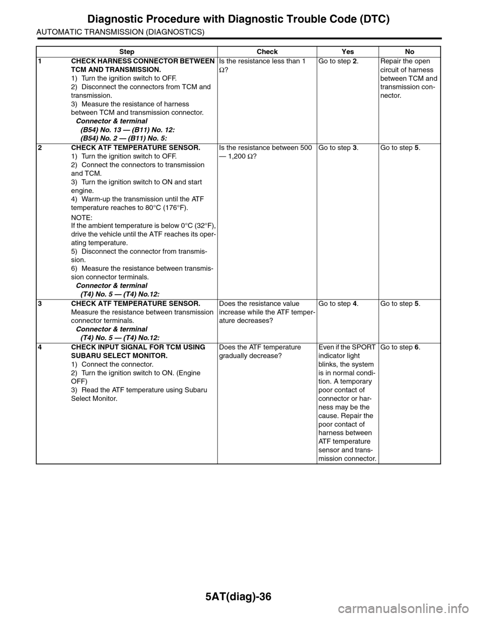
5AT(diag)-36
Diagnostic Procedure with Diagnostic Trouble Code (DTC)
AUTOMATIC TRANSMISSION (DIAGNOSTICS)
Step Check Yes No
1CHECK HARNESS CONNECTOR BETWEEN
TCM AND TRANSMISSION.
1) Turn the ignition switch to OFF.
2) Disconnect the connectors from TCM and
transmission.
3) Measure the resistance of harness
between TCM and transmission connector.
Connector & terminal
(B54) No. 13 — (B11) No. 12:
(B54) No. 2 — (B11) No. 5:
Is the resistance less than 1
Ω?
Go to step 2.Repair the open
circuit of harness
between TCM and
transmission con-
nector.
2CHECK ATF TEMPERATURE SENSOR.
1) Turn the ignition switch to OFF.
2) Connect the connectors to transmission
and TCM.
3) Turn the ignition switch to ON and start
engine.
4) Warm-up the transmission until the ATF
temperature reaches to 80°C (176°F).
NOTE:
If the ambient temperature is below 0°C (32°F),
drive the vehicle until the ATF reaches its oper-
ating temperature.
5) Disconnect the connector from transmis-
sion.
6) Measure the resistance between transmis-
sion connector terminals.
Connector & terminal
(T4) No. 5 — (T4) No.12:
Is the resistance between 500
— 1,200 Ω?
Go to step 3.Go to step 5.
3CHECK ATF TEMPERATURE SENSOR.
Measure the resistance between transmission
connector terminals.
Connector & terminal
(T4) No. 5 — (T4) No.12:
Does the resistance value
increase while the ATF temper-
ature decreases?
Go to step 4.Go to step 5.
4CHECK INPUT SIGNAL FOR TCM USING
SUBARU SELECT MONITOR.
1) Connect the connector.
2) Turn the ignition switch to ON. (Engine
OFF)
3) Read the ATF temperature using Subaru
Select Monitor.
Does the ATF temperature
gradually decrease?
Even if the SPORT
indicator light
blinks, the system
is in normal condi-
tion. A temporary
poor contact of
connector or har-
ness may be the
cause. Repair the
poor contact of
harness between
AT F t e m p e r a t u r e
sensor and trans-
mission connector.
Go to step 6.
Page 2156 of 2453
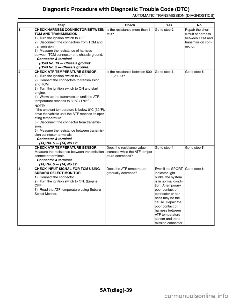
5AT(diag)-39
Diagnostic Procedure with Diagnostic Trouble Code (DTC)
AUTOMATIC TRANSMISSION (DIAGNOSTICS)
Step Check Yes No
1CHECK HARNESS CONNECTOR BETWEEN
TCM AND TRANSMISSION.
1) Turn the ignition switch to OFF.
2) Disconnect the connectors from TCM and
transmission.
3) Measure the resistance of harness
between TCM connector and chassis ground.
Connector & terminal
(B54) No. 13 — Chassis ground:
(B54) No. 2 — Chassis ground:
Is the resistance more than 1
MΩ?
Go to step 2.Repair the short
circuit of harness
between TCM and
transmission con-
nector.
2CHECK ATF TEMPERATURE SENSOR.
1) Turn the ignition switch to OFF.
2) Connect the connectors to transmission
and TCM.
3) Turn the ignition switch to ON and start
engine.
4) Warm-up the transmission until the ATF
temperature reaches to 80°C (176°F).
NOTE:
If the ambient temperature is below 0°C (32°F),
drive the vehicle until the ATF reaches its oper-
ating temperature.
5) Disconnect the connector from transmis-
sion.
6) Measure the resistance between transmis-
sion connector terminals.
Connector & terminal
(T4) No. 5 — (T4) No.12:
Is the resistance between 500
— 1,200 Ω?
Go to step 3.Go to step 5.
3CHECK ATF TEMPERATURE SENSOR.
Measure the resistance between transmission
connector terminals.
Connector & terminal
(T4) No. 5 — (T4) No.12:
Does the resistance value
increase while the ATF temper-
ature decreases?
Go to step 4.Go to step 5.
4CHECK INPUT SIGNAL FOR TCM USING
SUBARU SELECT MONITOR.
1) Connect the connector.
2) Turn the ignition switch to ON. (Engine
OFF)
3) Read the ATF temperature using Subaru
Select Monitor.
Does the ATF temperature
gradually decrease?
Even if the SPORT
indicator light
blinks, the system
is in normal condi-
tion. A temporary
poor contact of
connector or har-
ness may be the
cause. Repair the
poor contact of
harness between
AT F t e m p e r a t u r e
sensor and trans-
mission connector.
Go to step 6.
Page 2159 of 2453
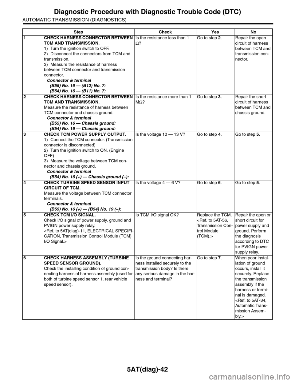
5AT(diag)-42
Diagnostic Procedure with Diagnostic Trouble Code (DTC)
AUTOMATIC TRANSMISSION (DIAGNOSTICS)
Step Check Yes No
1CHECK HARNESS CONNECTOR BETWEEN
TCM AND TRANSMISSION.
1) Turn the ignition switch to OFF.
2) Disconnect the connectors from TCM and
transmission.
3) Measure the resistance of harness
between TCM connector and transmission
connector.
Connector & terminal
(B55) No. 16 — (B12) No. 7:
(B54) No. 16 — (B11) No. 7:
Is the resistance less than 1
Ω?
Go to step 2.Repair the open
circuit of harness
between TCM and
transmission con-
nector.
2CHECK HARNESS CONNECTOR BETWEEN
TCM AND TRANSMISSION.
Measure the resistance of harness between
TCM connector and chassis ground.
Connector & terminal
(B55) No. 16 — Chassis ground:
(B54) No. 16 — Chassis ground:
Is the resistance more than 1
MΩ?
Go to step 3.Repair the short
circuit of harness
between TCM and
chassis ground.
3CHECK TCM POWER SUPPLY OUTPUT.
1) Connect the TCM connector. (Transmission
connector is disconnected)
2) Turn the ignition switch to ON. (Engine
OFF)
3) Measure the voltage between TCM con-
nector and chassis ground.
Connector & terminal
(B54) No. 16 (+) — Chassis ground (–):
Is the voltage 10 — 13 V? Go to step 4.Go to step 5.
4CHECK TURBINE SPEED SENSOR INPUT
CIRCUIT OF TCM.
Measure the voltage between TCM connector
terminals.
Connector & terminal
(B55) No. 16 (+) — (B54) No. 19 (–):
Is the voltage 4 — 6 V? Go to step 6.Go to step 5.
5CHECK TCM I/O SIGNAL.
Check I/O signal of power supply, ground and
PVIGN power supply relay.
I/O Signal.>
Is TCM I/O signal OK? Replace the TCM.
trol Module
(TCM).>
Repair the open or
short circuit for
power supply and
ground. Perform
the diagnosis
according to DTC
for PVIGN power
supply relay.
6CHECK HARNESS ASSEMBLY (TURBINE
SPEED SENSOR GROUND).
Check the installing condition of ground con-
necting harness of harness assembly (used for
both of turbine speed sensor 1, rear vehicle
speed sensor).
Is the ground connecting har-
ness installed securely to the
transmission body? Is there
any serious damage in the har-
ness and terminal?
Go to step 7.When poor instal-
lation of ground
occurs, install it
securely. Replace
the transmission
assembly if the
harness or termi-
nal is damaged.
mission Assem-
bly.>
Page 2160 of 2453
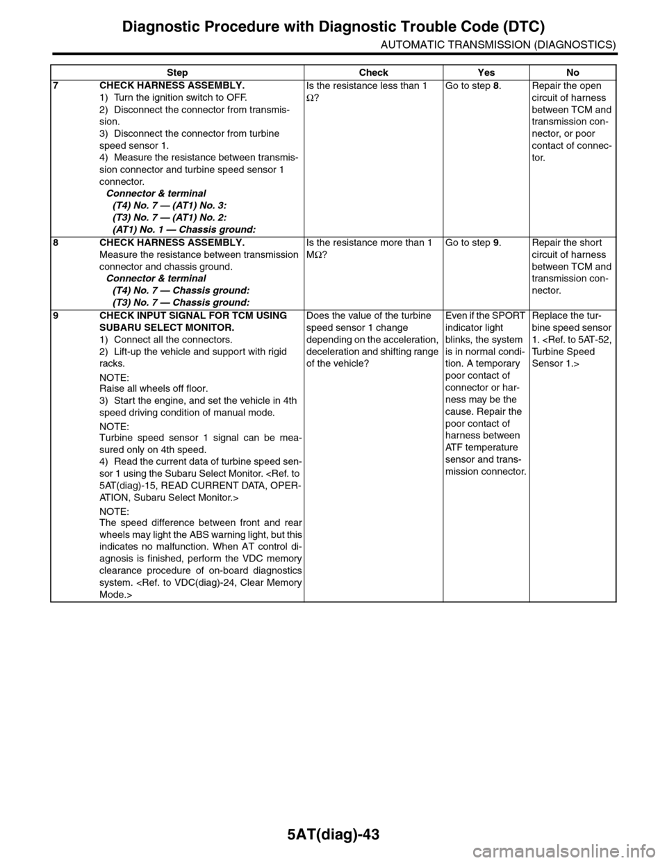
5AT(diag)-43
Diagnostic Procedure with Diagnostic Trouble Code (DTC)
AUTOMATIC TRANSMISSION (DIAGNOSTICS)
7CHECK HARNESS ASSEMBLY.
1) Turn the ignition switch to OFF.
2) Disconnect the connector from transmis-
sion.
3) Disconnect the connector from turbine
speed sensor 1.
4) Measure the resistance between transmis-
sion connector and turbine speed sensor 1
connector.
Connector & terminal
(T4) No. 7 — (AT1) No. 3:
(T3) No. 7 — (AT1) No. 2:
(AT1) No. 1 — Chassis ground:
Is the resistance less than 1
Ω?
Go to step 8.Repair the open
circuit of harness
between TCM and
transmission con-
nector, or poor
contact of connec-
tor.
8CHECK HARNESS ASSEMBLY.
Measure the resistance between transmission
connector and chassis ground.
Connector & terminal
(T4) No. 7 — Chassis ground:
(T3) No. 7 — Chassis ground:
Is the resistance more than 1
MΩ?
Go to step 9.Repair the short
circuit of harness
between TCM and
transmission con-
nector.
9CHECK INPUT SIGNAL FOR TCM USING
SUBARU SELECT MONITOR.
1) Connect all the connectors.
2) Lift-up the vehicle and support with rigid
racks.
NOTE:Raise all wheels off floor.
3) Start the engine, and set the vehicle in 4th
speed driving condition of manual mode.
NOTE:Turbine speed sensor 1 signal can be mea-
sured only on 4th speed.
4) Read the current data of turbine speed sen-
sor 1 using the Subaru Select Monitor.
AT I O N , S u b a r u S e l e c t M o n i t o r . >
NOTE:The speed difference between front and rear
wheels may light the ABS warning light, but this
indicates no malfunction. When AT control di-
agnosis is finished, perform the VDC memory
clearance procedure of on-board diagnostics
system.
Does the value of the turbine
speed sensor 1 change
depending on the acceleration,
deceleration and shifting range
of the vehicle?
Even if the SPORT
indicator light
blinks, the system
is in normal condi-
tion. A temporary
poor contact of
connector or har-
ness may be the
cause. Repair the
poor contact of
harness between
AT F t e m p e r a t u r e
sensor and trans-
mission connector.
Replace the tur-
bine speed sensor
1.
Sensor 1.>
Step Check Yes No
Page 2162 of 2453
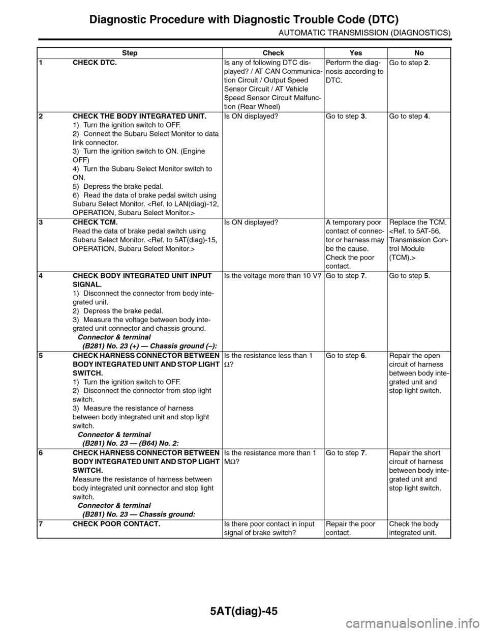
5AT(diag)-45
Diagnostic Procedure with Diagnostic Trouble Code (DTC)
AUTOMATIC TRANSMISSION (DIAGNOSTICS)
Step Check Yes No
1CHECK DTC.Is any of following DTC dis-
played? / AT CAN Communica-
tion Circuit / Output Speed
Sensor Circuit / AT Vehicle
Speed Sensor Circuit Malfunc-
tion (Rear Wheel)
Pe r for m t h e d ia g -
nosis according to
DTC.
Go to step 2.
2CHECK THE BODY INTEGRATED UNIT.
1) Turn the ignition switch to OFF.
2) Connect the Subaru Select Monitor to data
link connector.
3) Turn the ignition switch to ON. (Engine
OFF)
4) Turn the Subaru Select Monitor switch to
ON.
5) Depress the brake pedal.
6) Read the data of brake pedal switch using
Subaru Select Monitor.
Is ON displayed? Go to step 3.Go to step 4.
3CHECK TCM.
Read the data of brake pedal switch using
Subaru Select Monitor.
Is ON displayed? A temporary poor
contact of connec-
tor or harness may
be the cause.
Check the poor
contact.
Replace the TCM.
trol Module
(TCM).>
4CHECK BODY INTEGRATED UNIT INPUT
SIGNAL.
1) Disconnect the connector from body inte-
grated unit.
2) Depress the brake pedal.
3) Measure the voltage between body inte-
grated unit connector and chassis ground.
Connector & terminal
(B281) No. 23 (+) — Chassis ground (–):
Is the voltage more than 10 V? Go to step 7.Go to step 5.
5CHECK HARNESS CONNECTOR BETWEEN
BODY INTEGRATED UNIT AND STOP LIGHT
SWITCH.
1) Turn the ignition switch to OFF.
2) Disconnect the connector from stop light
switch.
3) Measure the resistance of harness
between body integrated unit and stop light
switch.
Connector & terminal
(B281) No. 23 — (B64) No. 2:
Is the resistance less than 1
Ω?
Go to step 6.Repair the open
circuit of harness
between body inte-
grated unit and
stop light switch.
6CHECK HARNESS CONNECTOR BETWEEN
BODY INTEGRATED UNIT AND STOP LIGHT
SWITCH.
Measure the resistance of harness between
body integrated unit connector and stop light
switch.
Connector & terminal
(B281) No. 23 — Chassis ground:
Is the resistance more than 1
MΩ?
Go to step 7.Repair the short
circuit of harness
between body inte-
grated unit and
stop light switch.
7CHECK POOR CONTACT.Is there poor contact in input
signal of brake switch?
Repair the poor
contact.
Check the body
integrated unit.
Page 2164 of 2453
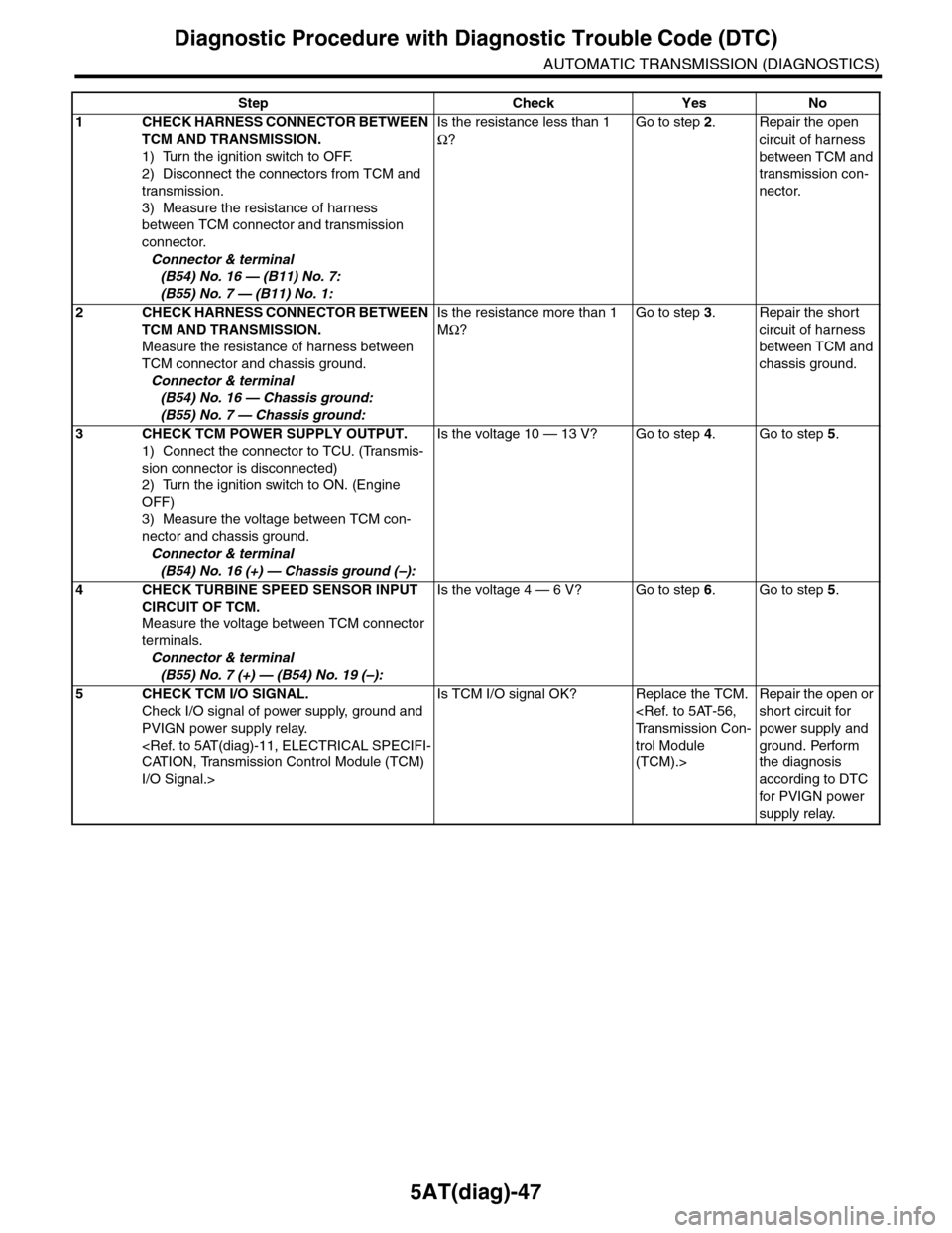
5AT(diag)-47
Diagnostic Procedure with Diagnostic Trouble Code (DTC)
AUTOMATIC TRANSMISSION (DIAGNOSTICS)
Step Check Yes No
1CHECK HARNESS CONNECTOR BETWEEN
TCM AND TRANSMISSION.
1) Turn the ignition switch to OFF.
2) Disconnect the connectors from TCM and
transmission.
3) Measure the resistance of harness
between TCM connector and transmission
connector.
Connector & terminal
(B54) No. 16 — (B11) No. 7:
(B55) No. 7 — (B11) No. 1:
Is the resistance less than 1
Ω?
Go to step 2.Repair the open
circuit of harness
between TCM and
transmission con-
nector.
2CHECK HARNESS CONNECTOR BETWEEN
TCM AND TRANSMISSION.
Measure the resistance of harness between
TCM connector and chassis ground.
Connector & terminal
(B54) No. 16 — Chassis ground:
(B55) No. 7 — Chassis ground:
Is the resistance more than 1
MΩ?
Go to step 3.Repair the short
circuit of harness
between TCM and
chassis ground.
3CHECK TCM POWER SUPPLY OUTPUT.
1) Connect the connector to TCU. (Transmis-
sion connector is disconnected)
2) Turn the ignition switch to ON. (Engine
OFF)
3) Measure the voltage between TCM con-
nector and chassis ground.
Connector & terminal
(B54) No. 16 (+) — Chassis ground (–):
Is the voltage 10 — 13 V? Go to step 4.Go to step 5.
4CHECK TURBINE SPEED SENSOR INPUT
CIRCUIT OF TCM.
Measure the voltage between TCM connector
terminals.
Connector & terminal
(B55) No. 7 (+) — (B54) No. 19 (–):
Is the voltage 4 — 6 V? Go to step 6.Go to step 5.
5CHECK TCM I/O SIGNAL.
Check I/O signal of power supply, ground and
PVIGN power supply relay.
I/O Signal.>
Is TCM I/O signal OK? Replace the TCM.
trol Module
(TCM).>
Repair the open or
short circuit for
power supply and
ground. Perform
the diagnosis
according to DTC
for PVIGN power
supply relay.
Page 2165 of 2453
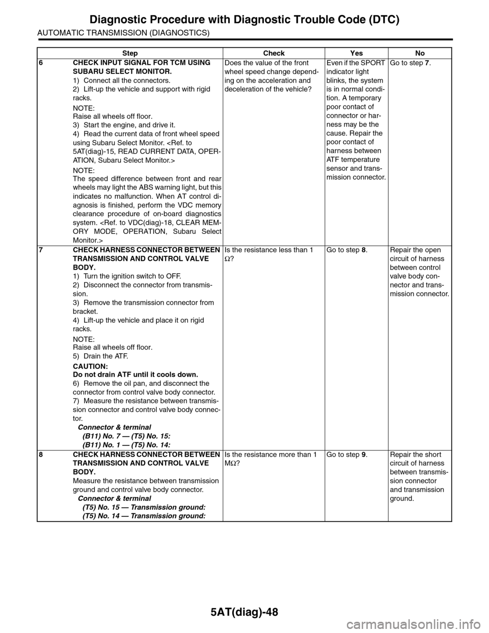
5AT(diag)-48
Diagnostic Procedure with Diagnostic Trouble Code (DTC)
AUTOMATIC TRANSMISSION (DIAGNOSTICS)
6CHECK INPUT SIGNAL FOR TCM USING
SUBARU SELECT MONITOR.
1) Connect all the connectors.
2) Lift-up the vehicle and support with rigid
racks.
NOTE:
Raise all wheels off floor.
3) Start the engine, and drive it.
4) Read the current data of front wheel speed
using Subaru Select Monitor.
AT I O N , S u b a r u S e l e c t M o n i t o r . >
NOTE:
The speed difference between front and rear
wheels may light the ABS warning light, but this
indicates no malfunction. When AT control di-
agnosis is finished, perform the VDC memory
clearance procedure of on-board diagnostics
system.
Monitor.>
Does the value of the front
wheel speed change depend-
ing on the acceleration and
deceleration of the vehicle?
Even if the SPORT
indicator light
blinks, the system
is in normal condi-
tion. A temporary
poor contact of
connector or har-
ness may be the
cause. Repair the
poor contact of
harness between
AT F t e m p e r a t u r e
sensor and trans-
mission connector.
Go to step 7.
7CHECK HARNESS CONNECTOR BETWEEN
TRANSMISSION AND CONTROL VALVE
BODY.
1) Turn the ignition switch to OFF.
2) Disconnect the connector from transmis-
sion.
3) Remove the transmission connector from
bracket.
4) Lift-up the vehicle and place it on rigid
racks.
NOTE:Raise all wheels off floor.
5) Drain the ATF.
CAUTION:Do not drain ATF until it cools down.
6) Remove the oil pan, and disconnect the
connector from control valve body connector.
7) Measure the resistance between transmis-
sion connector and control valve body connec-
tor.
Connector & terminal
(B11) No. 7 — (T5) No. 15:
(B11) No. 1 — (T5) No. 14:
Is the resistance less than 1
Ω?
Go to step 8.Repair the open
circuit of harness
between control
valve body con-
nector and trans-
mission connector.
8CHECK HARNESS CONNECTOR BETWEEN
TRANSMISSION AND CONTROL VALVE
BODY.
Measure the resistance between transmission
ground and control valve body connector.
Connector & terminal
(T5) No. 15 — Transmission ground:
(T5) No. 14 — Transmission ground:
Is the resistance more than 1
MΩ?
Go to step 9.Repair the short
circuit of harness
between transmis-
sion connector
and transmission
ground.
Step Check Yes No