fuse list SUBARU TRIBECA 2009 1.G Service Workshop Manual
[x] Cancel search | Manufacturer: SUBARU, Model Year: 2009, Model line: TRIBECA, Model: SUBARU TRIBECA 2009 1.GPages: 2453, PDF Size: 46.32 MB
Page 69 of 2453
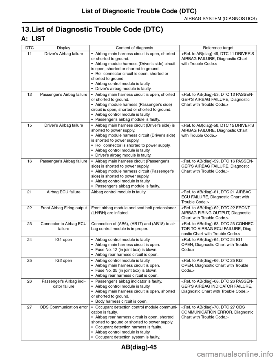
AB(diag)-45
List of Diagnostic Trouble Code (DTC)
AIRBAG SYSTEM (DIAGNOSTICS)
13.List of Diagnostic Trouble Code (DTC)
A: LIST
DTC Display Content of diagnosis Reference target
11 Driver’s Airbag failure • Airbag main harness circuit is open, shorted
or shorted to ground.
•Airbag module harness (Driver's side) circuit
is open, shorted or shorted to ground.
•Roll connector circuit is open, shorted or
shorted to ground.
•Airbag control module is faulty.
•Driver's airbag module is faulty.
with Trouble Code.>
12 Passenger's Airbag failure • Airbag main harness circuit is open, shorted
or shorted to ground.
•Airbag module harness (Passenger's side)
circuit is open, shorted or shorted to ground.
•Airbag control module is faulty.
•Passenger's airbag module is faulty.
Chart with Trouble Code.>
15 Driver’s Airbag failure • Airbag main harness circuit (Driver’s side) is
shorted to power supply.
•Airbag module harness circuit (Driver’s side)
is shorted to power supply.
•Roll connector is shorted to power supply.
•Airbag control module is faulty.
•Driver’s airbag module is faulty.
with Trouble Code.>
16 Passenger's Airbag failure • Airbag main harness circuit (Passenger's
side) is shorted to power supply.
•Airbag module harness circuit (Passenger's
side) is shorted to power supply.
•Airbag control module is faulty.
•Passenger's airbag module is faulty.
Chart with Trouble Code.>
21 Airbag ECU failure Airbag control module is faulty.
Tr o u b l e C o d e . >
22 Front Airbag Firing output Front airbag module and seat belt pretensioner
(LH/RH) are inflated.
Chart with Trouble Code.>
23 Connector to Airbag ECU
failure
Connection of (AB6), (AB17) and (AB18) to air-
bag control module is improper.
nostic Chart with Trouble Code.>
24 IG1 open • Airbag control module is faulty.
•Airbag main harness circuit is open.
•Fuse No. 12 (in joint box) is blown.
•Airbag rear harness circuit is open.
Code.>
25 IG2 open • Airbag control module is faulty.
•Airbag main harness circuit is open.
•Fuse No. 25 (in joint box) is blown.
•Airbag rear harness circuit is open.
Code.>
26 Passenger's Airbag indi-
cator failure
•Passenger's airbag indicator is faulty.
•Airbag control module is faulty.
•Airbag main harness circuit is open, shorted
or shorted to ground.
•Body harness circuit is open.
Diagnostic Chart with Trouble Code.>
27 ODS Communication error • Occupant detection control module communi-
cation is faulty.
•Airbag rear harness circuit is open, shorted,
shorted to ground or shorted to power supply.
•Occupant detection harness is faulty.
•Airbag control module is faulty.
•Occupant detection system is faulty.
Chart with Trouble Code.>
Page 70 of 2453
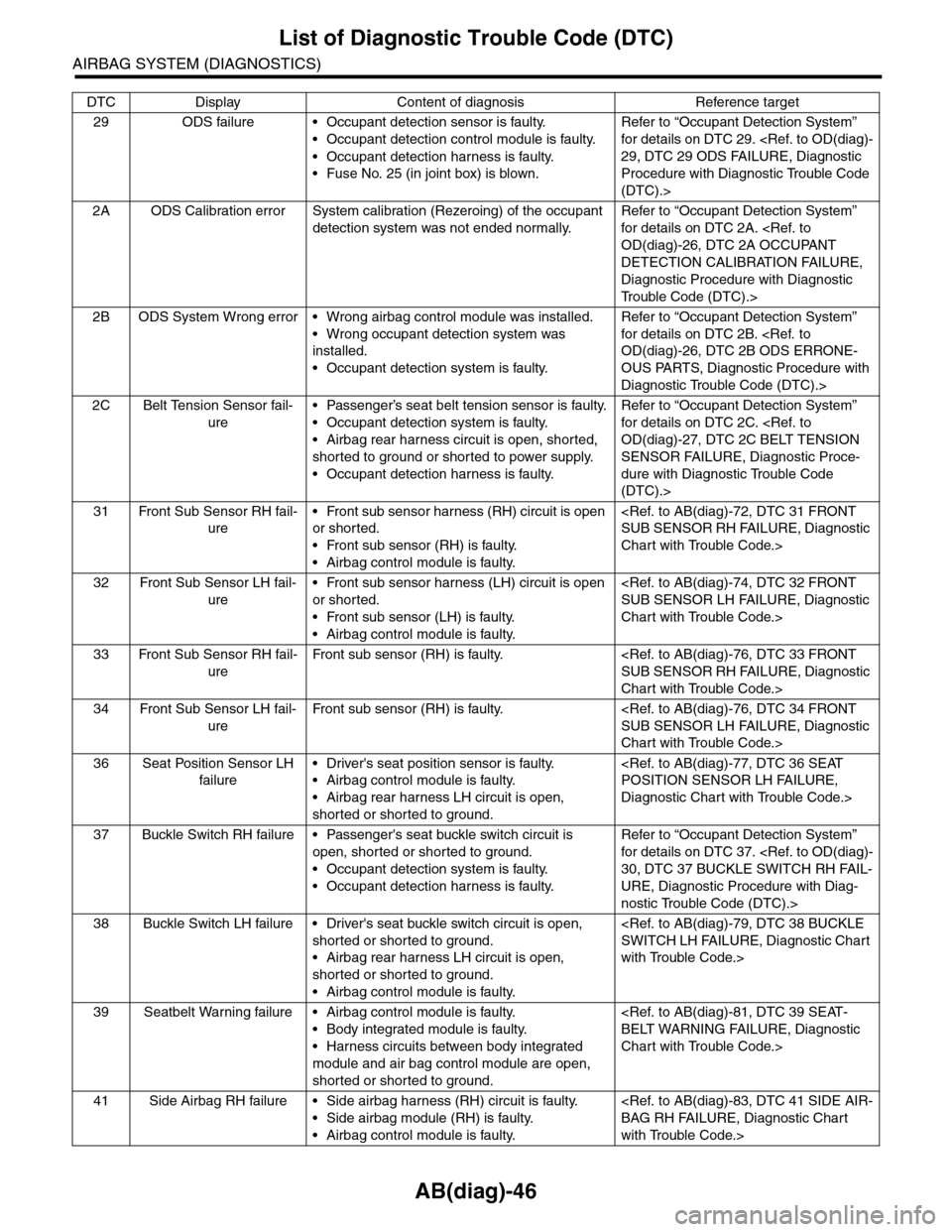
AB(diag)-46
List of Diagnostic Trouble Code (DTC)
AIRBAG SYSTEM (DIAGNOSTICS)
29 ODS failure • Occupant detection sensor is faulty.
•Occupant detection control module is faulty.
•Occupant detection harness is faulty.
•Fuse No. 25 (in joint box) is blown.
Refer to “Occupant Detection System”
for details on DTC 29.
Procedure with Diagnostic Trouble Code
(DTC).>
2A ODS Calibration error System calibration (Rezeroing) of the occupant
detection system was not ended normally.
Refer to “Occupant Detection System”
for details on DTC 2A.
DETECTION CALIBRATION FAILURE,
Diagnostic Procedure with Diagnostic
Tr o u b l e C o d e ( D T C ) . >
2B ODS System Wrong error • Wrong airbag control module was installed.
•Wrong occupant detection system was
installed.
•Occupant detection system is faulty.
Refer to “Occupant Detection System”
for details on DTC 2B.
OUS PARTS, Diagnostic Procedure with
Diagnostic Trouble Code (DTC).>
2C Belt Tension Sensor fail-
ure
•Passenger’s seat belt tension sensor is faulty.
•Occupant detection system is faulty.
•Airbag rear harness circuit is open, shorted,
shorted to ground or shorted to power supply.
•Occupant detection harness is faulty.
Refer to “Occupant Detection System”
for details on DTC 2C.
SENSOR FAILURE, Diagnostic Proce-
dure with Diagnostic Trouble Code
(DTC).>
31 Front Sub Sensor RH fail-
ure
•Front sub sensor harness (RH) circuit is open
or shorted.
•Front sub sensor (RH) is faulty.
•Airbag control module is faulty.
Chart with Trouble Code.>
32 Front Sub Sensor LH fail-
ure
•Front sub sensor harness (LH) circuit is open
or shorted.
•Front sub sensor (LH) is faulty.
•Airbag control module is faulty.
Chart with Trouble Code.>
33 Front Sub Sensor RH fail-
ure
Fr o nt su b se ns or ( RH) i s fa u lt y. < Re f. t o A B ( d ia g ) - 76 , D TC 3 3 F RONT
SUB SENSOR RH FAILURE, Diagnostic
Chart with Trouble Code.>
34 Front Sub Sensor LH fail-
ure
Fr o nt su b se ns or ( RH) i s fa u lt y. < Re f. t o A B ( d ia g ) - 76 , D TC 3 4 F RONT
SUB SENSOR LH FAILURE, Diagnostic
Chart with Trouble Code.>
36 Seat Position Sensor LH
failure
•Driver's seat position sensor is faulty.
•Airbag control module is faulty.
•Airbag rear harness LH circuit is open,
shorted or shorted to ground.
Diagnostic Chart with Trouble Code.>
37 Buckle Switch RH failure • Passenger's seat buckle switch circuit is
open, shorted or shorted to ground.
•Occupant detection system is faulty.
•Occupant detection harness is faulty.
Refer to “Occupant Detection System”
for details on DTC 37.
URE, Diagnostic Procedure with Diag-
nostic Trouble Code (DTC).>
38 Buckle Switch LH failure • Driver's seat buckle switch circuit is open,
shorted or shorted to ground.
•Airbag rear harness LH circuit is open,
shorted or shorted to ground.
•Airbag control module is faulty.
with Trouble Code.>
39 Seatbelt Warning failure • Airbag control module is faulty.
•Body integrated module is faulty.
•Harness circuits between body integrated
module and air bag control module are open,
shorted or shorted to ground.
Chart with Trouble Code.>
41 Side Airbag RH failure • Side airbag harness (RH) circuit is faulty.
•Side airbag module (RH) is faulty.
•Airbag control module is faulty.
with Trouble Code.>
DTC Display Content of diagnosis Reference target
Page 89 of 2453
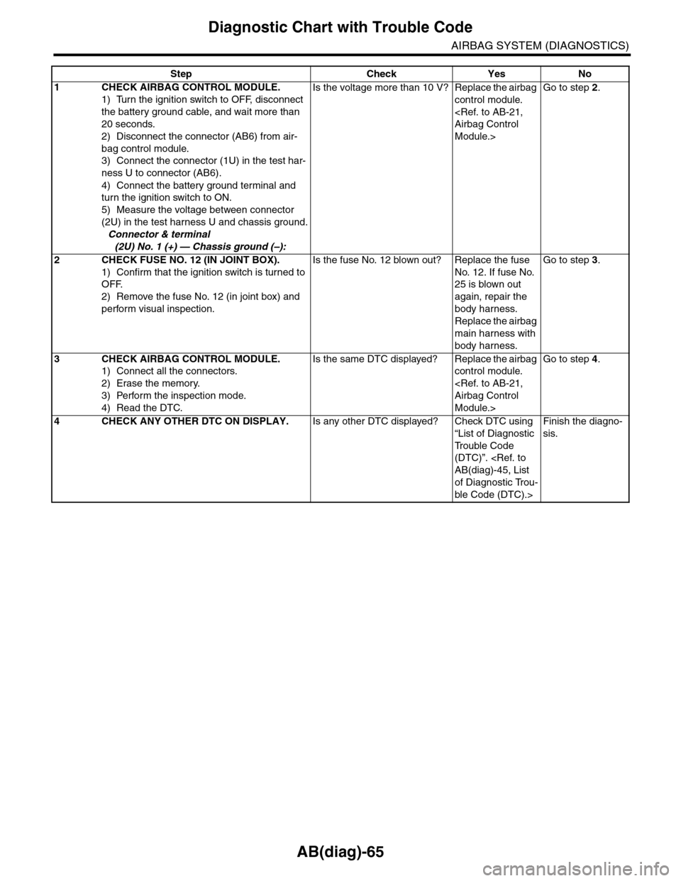
AB(diag)-65
Diagnostic Chart with Trouble Code
AIRBAG SYSTEM (DIAGNOSTICS)
Step Check Yes No
1CHECK AIRBAG CONTROL MODULE.
1) Turn the ignition switch to OFF, disconnect
the battery ground cable, and wait more than
20 seconds.
2) Disconnect the connector (AB6) from air-
bag control module.
3) Connect the connector (1U) in the test har-
ness U to connector (AB6).
4) Connect the battery ground terminal and
turn the ignition switch to ON.
5) Measure the voltage between connector
(2U) in the test harness U and chassis ground.
Connector & terminal
(2U) No. 1 (+) — Chassis ground (–):
Is the voltage more than 10 V? Replace the airbag
control module.
Module.>
Go to step 2.
2CHECK FUSE NO. 12 (IN JOINT BOX).
1) Confirm that the ignition switch is turned to
OFF.
2) Remove the fuse No. 12 (in joint box) and
perform visual inspection.
Is the fuse No. 12 blown out? Replace the fuse
No. 12. If fuse No.
25 is blown out
again, repair the
body harness.
Replace the airbag
main harness with
body harness.
Go to step 3.
3CHECK AIRBAG CONTROL MODULE.
1) Connect all the connectors.
2) Erase the memory.
3) Perform the inspection mode.
4) Read the DTC.
Is the same DTC displayed? Replace the airbag
control module.
Module.>
Go to step 4.
4CHECK ANY OTHER DTC ON DISPLAY.Is any other DTC displayed? Check DTC using
“List of Diagnostic
Tr o u b l e C o d e
(DTC)”.
of Diagnostic Trou-
ble Code (DTC).>
Finish the diagno-
sis.
Page 91 of 2453

AB(diag)-67
Diagnostic Chart with Trouble Code
AIRBAG SYSTEM (DIAGNOSTICS)
Step Check Yes No
1CHECK AIRBAG CONTROL MODULE.
1) Turn the ignition switch to OFF, disconnect
the battery ground cable, and wait more than
20 seconds.
2) Disconnect the connector (AB6) from air-
bag control module.
3) Connect the connector (1U) in the test har-
ness U to connector (AB6).
4) Connect the battery ground terminal and
turn the ignition switch to ON.
5) Measure the voltage between connector
(2U) in the test harness U and chassis ground.
Connector & terminal
(2U) No. 6 (+) — Chassis ground (–):
Is the voltage more than 10 V? Replace the airbag
control module.
Module.>
Go to step 2.
2CHECK FUSE NO. 25 (IN JOINT BOX).
1) Confirm that the ignition switch is turned to
OFF.
2) Remove the fuse No. 25 (in joint box) and
perform visual inspection.
Is the fuse No. 25 blown out? Replace the fuse
No. 25. If fuse No.
12 is blown out
again, repair the
body harness. Or
replace the airbag
main harness with
body harness.
Go to step 3.
3CHECK AIRBAG CONTROL MODULE.
1) Connect all the connectors.
2) Erase the memory.
3) Perform the inspection mode.
4) Read the DTC.
Is the same DTC displayed? Replace the airbag
control module.
Module.>
Go to step 4.
4CHECK ANY OTHER DTC ON DISPLAY.Is any other DTC displayed? Check DTC using
“List of Diagnostic
Tr o u b l e C o d e
(DTC)”.
of Diagnostic Trou-
ble Code (DTC).>
Finish the diagno-
sis.
Page 175 of 2453
CC(ETC)(diag)-8
Subaru Select Monitor
CRUISE CONTROL SYSTEM (DIAGNOSTICS)
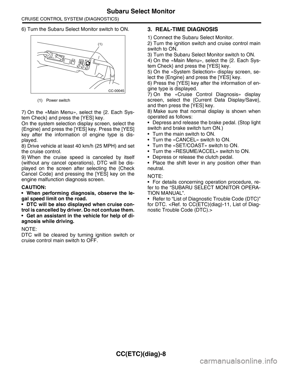
6) Turn the Subaru Select Monitor switch to ON.
7) On the «Main Menu», select the {2. Each Sys-
tem Check} and press the [YES] key.
On the system selection display screen, select the
{Engine} and press the [YES] key. Press the [YES]
key after the information of engine type is dis-
played.
8) Drive vehicle at least 40 km/h (25 MPH) and set
the cruise control.
9) When the cruise speed is canceled by itself
(without any cancel operations), DTC will be dis-
played on the screen after selecting the {Check
Cancel Code} and pressing the [YES] key on the
engine malfunction diagnosis screen.
CAUTION:
•When performing diagnosis, observe the le-
gal speed limit on the road.
•DTC will be also displayed when cruise con-
trol is cancelled by driver. Do not confuse them.
•Get an assistant in the vehicle for help of di-
agnosis while driving.
NOTE:
DTC will be cleared by turning ignition switch or
cruise control main switch to OFF.
3. REAL-TIME DIAGNOSIS
1) Connect the Subaru Select Monitor.
2) Turn the ignition switch and cruise control main
switch to ON.
3) Turn the Subaru Select Monitor switch to ON.
4) On the «Main Menu», select the {2. Each Sys-
tem Check} and press the [YES] key.
5) On the «System Selection» display screen, se-
lect the {Engine} and press the [YES] key.
6) Press the [YES] key after the information of en-
gine type is displayed.
7) On the «Cruise Control Diagnosis» display
screen, select the {Current Data Display/Save},
and then press the [YES] key.
8) Make sure that normal display is shown when
operated as follows:
•Depress and release the brake pedal. (Stop light
switch and brake switch turn ON.)
•Turn the main switch to ON.
•Turn the «CANCEL» switch to ON.
•Turn the «SET/COAST» switch to ON.
•Turn the «RESUME/ACCEL» switch to ON.
•Depress or release the clutch pedal.
•Place the shift lever in any position other than
neutral.
NOTE:
•For details concerning operation procedure, re-
fer to the “SUBARU SELECT MONITOR OPERA-
TION MANUAL”.
•Refer to “List of Diagnostic Trouble Code (DTC)”
for DTC.
(1) Power switch
CC-00045
(1)
Page 593 of 2453
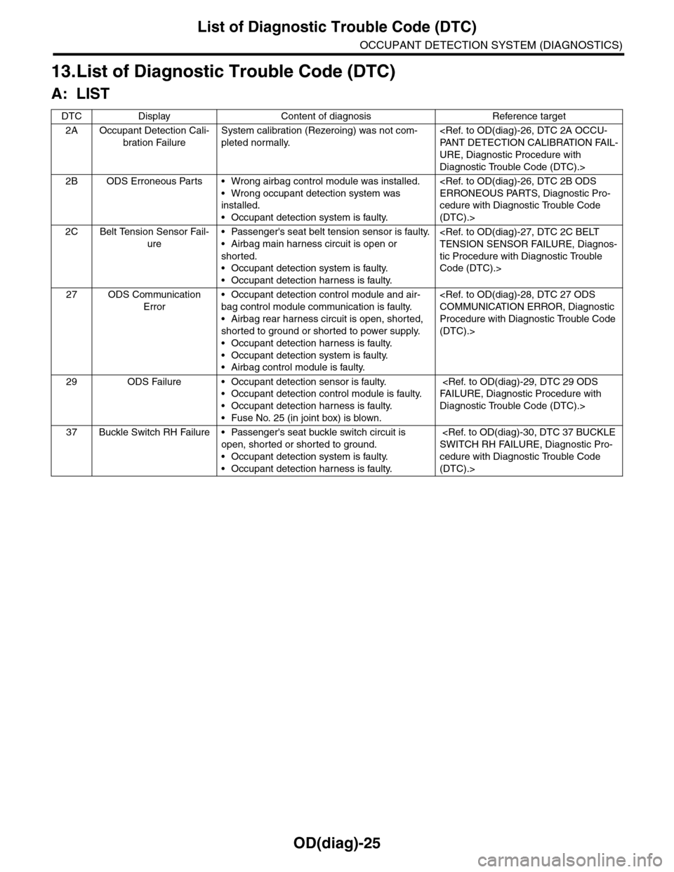
OD(diag)-25
List of Diagnostic Trouble Code (DTC)
OCCUPANT DETECTION SYSTEM (DIAGNOSTICS)
13.List of Diagnostic Trouble Code (DTC)
A: LIST
DTC Display Content of diagnosis Reference target
2A Occupant Detection Cali-
bration Failure
System calibration (Rezeroing) was not com-
pleted normally.
URE, Diagnostic Procedure with
Diagnostic Trouble Code (DTC).>
2B ODS Erroneous Parts • Wrong airbag control module was installed.
•Wrong occupant detection system was
installed.
•Occupant detection system is faulty.
cedure with Diagnostic Trouble Code
(DTC).>
2C Belt Tension Sensor Fail-
ure
•Passenger's seat belt tension sensor is faulty.
•Airbag main harness circuit is open or
shorted.
•Occupant detection system is faulty.
•Occupant detection harness is faulty.
tic Procedure with Diagnostic Trouble
Code (DTC).>
27 ODS Communication
Error
•Occupant detection control module and air-
bag control module communication is faulty.
•Airbag rear harness circuit is open, shorted,
shorted to ground or shorted to power supply.
•Occupant detection harness is faulty.
•Occupant detection system is faulty.
•Airbag control module is faulty.
Procedure with Diagnostic Trouble Code
(DTC).>
29 ODS Failure • Occupant detection sensor is faulty.
•Occupant detection control module is faulty.
•Occupant detection harness is faulty.
•Fuse No. 25 (in joint box) is blown.
Diagnostic Trouble Code (DTC).>
37 Buckle Switch RH Failure • Passenger's seat buckle switch circuit is
open, shorted or shorted to ground.
•Occupant detection system is faulty.
•Occupant detection harness is faulty.
cedure with Diagnostic Trouble Code
(DTC).>
Page 972 of 2453
TPM(diag)-22
Tire Pressure Warning Light/Trouble Indicator Light Illumination Pattern (DTC)
TIRE PRESSURE MONITORING SYSTEM (DIAGNOSTICS)
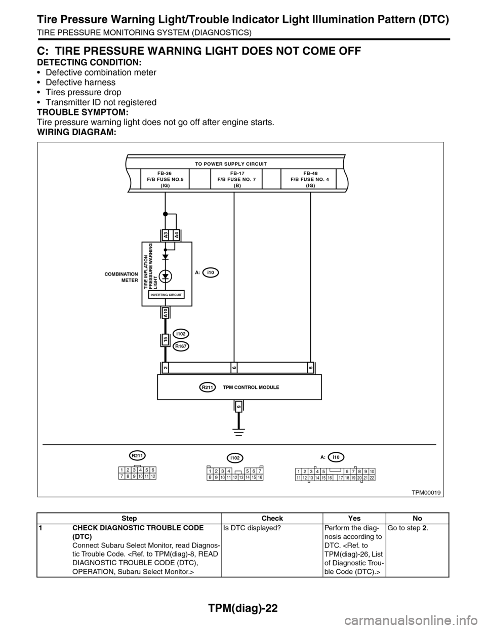
C: TIRE PRESSURE WARNING LIGHT DOES NOT COME OFF
DETECTING CONDITION:
•Defective combination meter
•Defective harness
•Tires pressure drop
•Transmitter ID not registered
TROUBLE SYMPTOM:
Tire pressure warning light does not go off after engine starts.
WIRING DIAGRAM:
TPM00019
TO POWER SUPPLY CIRCUIT
FB-36 F/B FUSE NO.5(IG)
26
COMBINATIONMETERA:i10
A3
A10
TIRE INFLATION PRESSURE WARNINGLIGHT
FB-17F/B FUSE NO. 7 (B)
i102
R167
R211
FB-48F/B FUSE NO. 4 (IG)
A4
INVERTING CIRCUIT
15
5
9
TPM CONTROL MODULE
i102
1238910411 12 1314 15 16567
A:i10
12345 678910111219 20 2113 14 15 161718 22
R211
123456789101112
Step Check Yes No
1CHECK DIAGNOSTIC TROUBLE CODE
(DTC)
Connect Subaru Select Monitor, read Diagnos-
tic Trouble Code.
OPERATION, Subaru Select Monitor.>
Is DTC displayed? Perform the diag-
nosis according to
DTC.
of Diagnostic Trou-
ble Code (DTC).>
Go to step 2.
Page 974 of 2453
TPM(diag)-24
Tire Pressure Warning Light/Trouble Indicator Light Illumination Pattern (DTC)
TIRE PRESSURE MONITORING SYSTEM (DIAGNOSTICS)
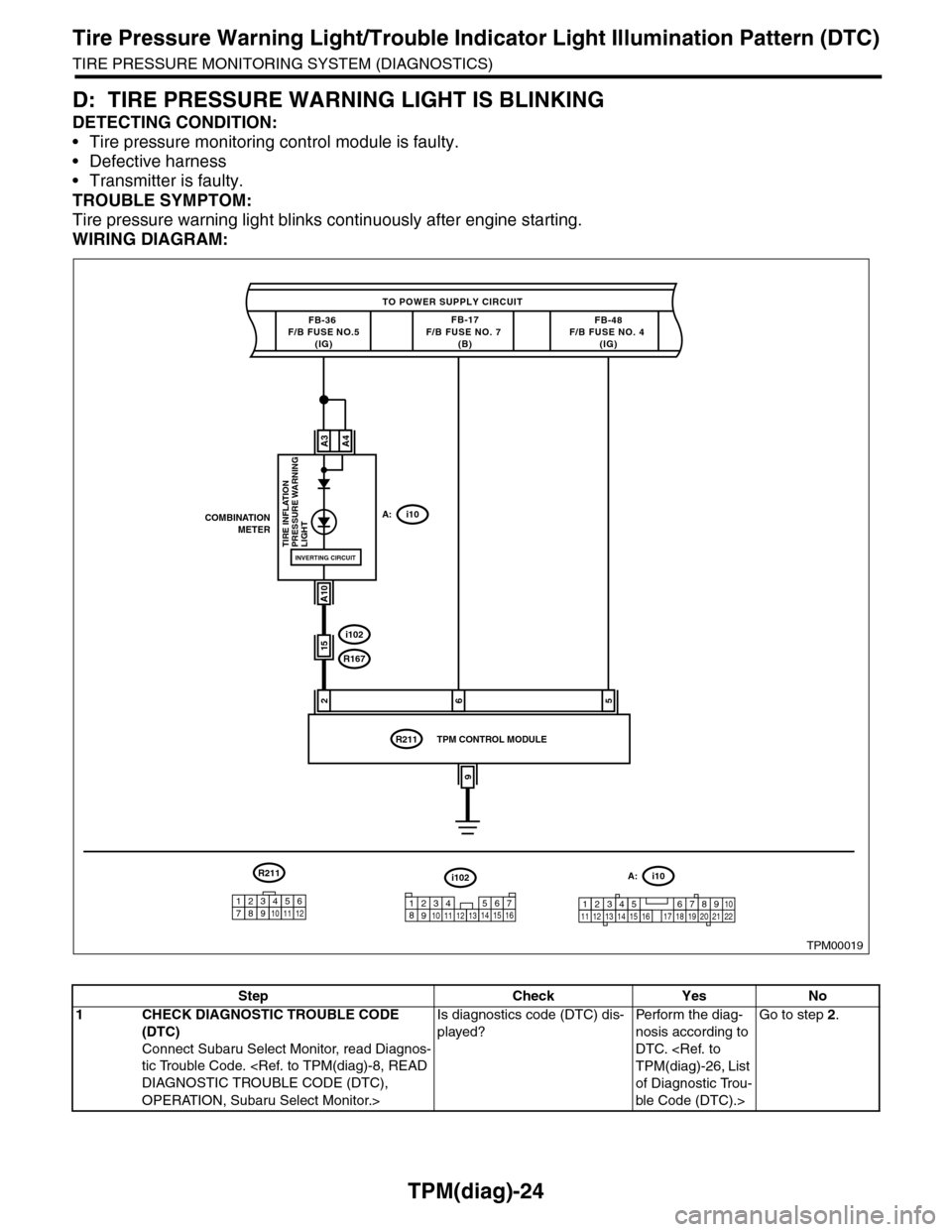
D: TIRE PRESSURE WARNING LIGHT IS BLINKING
DETECTING CONDITION:
•Tire pressure monitoring control module is faulty.
•Defective harness
•Transmitter is faulty.
TROUBLE SYMPTOM:
Tire pressure warning light blinks continuously after engine starting.
WIRING DIAGRAM:
TPM00019
TO POWER SUPPLY CIRCUIT
FB-36 F/B FUSE NO.5(IG)
26
COMBINATIONMETERA:i10
A3
A10
TIRE INFLATION PRESSURE WARNINGLIGHT
FB-17F/B FUSE NO. 7 (B)
i102
R167
R211
FB-48F/B FUSE NO. 4 (IG)
A4
INVERTING CIRCUIT
15
5
9
TPM CONTROL MODULE
i102
1238910411 12 1314 15 16567
A:i10
12345 678910111219 20 2113 14 15 161718 22
R211
123456789101112
Step Check Yes No
1CHECK DIAGNOSTIC TROUBLE CODE
(DTC)
Connect Subaru Select Monitor, read Diagnos-
tic Trouble Code.
OPERATION, Subaru Select Monitor.>
Is diagnostics code (DTC) dis-
played?
Pe r for m t h e d ia g -
nosis according to
DTC.
of Diagnostic Trou-
ble Code (DTC).>
Go to step 2.
Page 1220 of 2453
EN(H6DO)(diag)-59
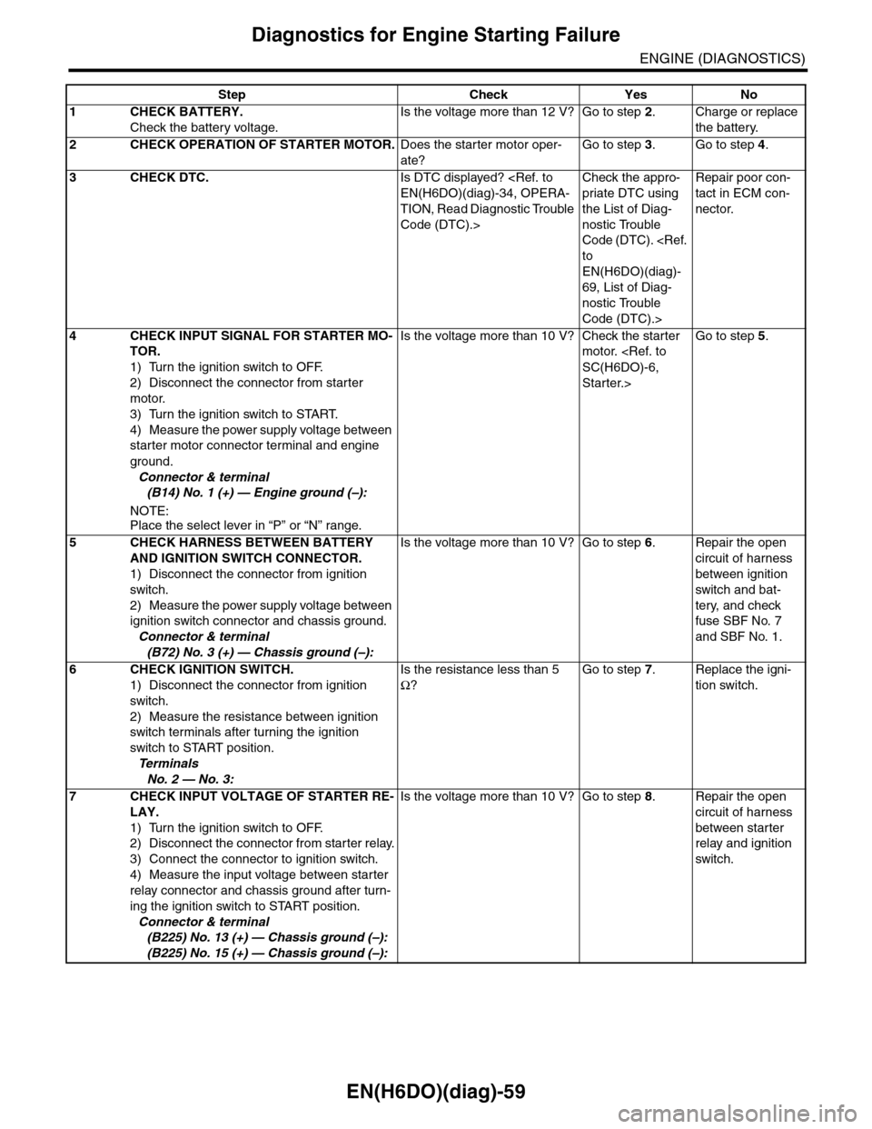
Diagnostics for Engine Starting Failure
ENGINE (DIAGNOSTICS)
Step Check Yes No
1CHECK BATTERY.
Check the battery voltage.
Is the voltage more than 12 V? Go to step 2.Charge or replace
the battery.
2CHECK OPERATION OF STARTER MOTOR.Does the starter motor oper-
ate?
Go to step 3.Go to step 4.
3CHECK DTC.Is DTC displayed?
TION, Read Diagnostic Trouble
Code (DTC).>
Check the appro-
priate DTC using
the List of Diag-
nostic Trouble
Code (DTC).
EN(H6DO)(diag)-
69, List of Diag-
nostic Trouble
Code (DTC).>
Repair poor con-
tact in ECM con-
nector.
4CHECK INPUT SIGNAL FOR STARTER MO-
TOR.
1) Turn the ignition switch to OFF.
2) Disconnect the connector from starter
motor.
3) Turn the ignition switch to START.
4) Measure the power supply voltage between
starter motor connector terminal and engine
ground.
Connector & terminal
(B14) No. 1 (+) — Engine ground (–):
NOTE:Place the select lever in “P” or “N” range.
Is the voltage more than 10 V? Check the starter
motor.
Starter.>
Go to step 5.
5CHECK HARNESS BETWEEN BATTERY
AND IGNITION SWITCH CONNECTOR.
1) Disconnect the connector from ignition
switch.
2) Measure the power supply voltage between
ignition switch connector and chassis ground.
Connector & terminal
(B72) No. 3 (+) — Chassis ground (–):
Is the voltage more than 10 V? Go to step 6.Repair the open
circuit of harness
between ignition
switch and bat-
tery, and check
fuse SBF No. 7
and SBF No. 1.
6CHECK IGNITION SWITCH.
1) Disconnect the connector from ignition
switch.
2) Measure the resistance between ignition
switch terminals after turning the ignition
switch to START position.
Te r m i n a l s
No. 2 — No. 3:
Is the resistance less than 5
Ω?
Go to step 7.Replace the igni-
tion switch.
7CHECK INPUT VOLTAGE OF STARTER RE-
LAY.
1) Turn the ignition switch to OFF.
2) Disconnect the connector from starter relay.
3) Connect the connector to ignition switch.
4) Measure the input voltage between starter
relay connector and chassis ground after turn-
ing the ignition switch to START position.
Connector & terminal
(B225) No. 13 (+) — Chassis ground (–):
(B225) No. 15 (+) — Chassis ground (–):
Is the voltage more than 10 V? Go to step 8.Repair the open
circuit of harness
between starter
relay and ignition
switch.
Page 2146 of 2453
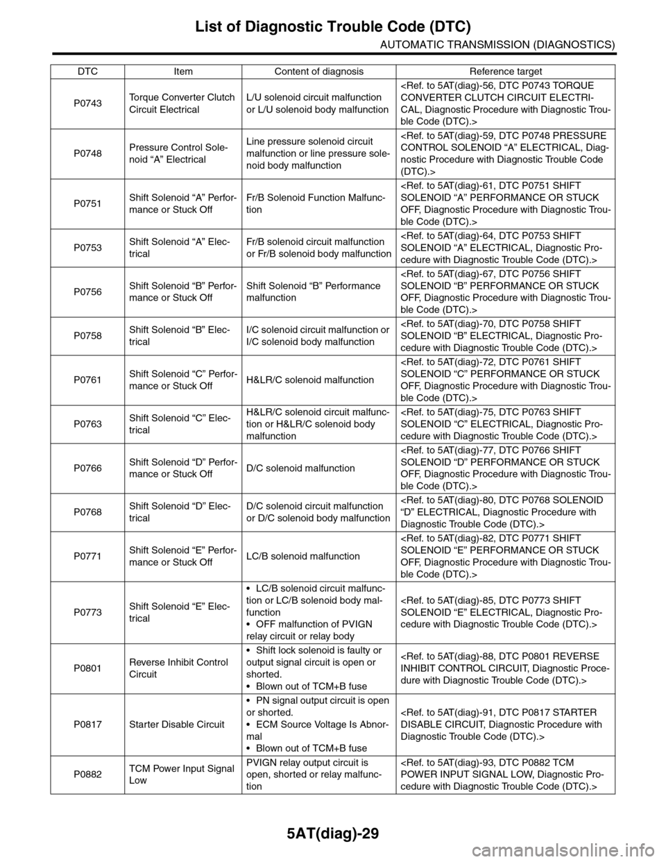
5AT(diag)-29
List of Diagnostic Trouble Code (DTC)
AUTOMATIC TRANSMISSION (DIAGNOSTICS)
P0743To r q u e C o n v e r t e r C l u t c h
Circuit Electrical
L/U solenoid circuit malfunction
or L/U solenoid body malfunction
CAL, Diagnostic Procedure with Diagnostic Trou-
ble Code (DTC).>
P0748Pressure Control Sole-
noid “A” Electrical
Line pressure solenoid circuit
malfunction or line pressure sole-
noid body malfunction
nostic Procedure with Diagnostic Trouble Code
(DTC).>
P0751Shift Solenoid “A” Perfor-
mance or Stuck Off
Fr/B Solenoid Function Malfunc-
tion
OFF, Diagnostic Procedure with Diagnostic Trou-
ble Code (DTC).>
P0753Shift Solenoid “A” Elec-
trical
Fr/B solenoid circuit malfunction
or Fr/B solenoid body malfunction
cedure with Diagnostic Trouble Code (DTC).>
P0756Shift Solenoid “B” Perfor-
mance or Stuck Off
Shift Solenoid “B” Performance
malfunction
OFF, Diagnostic Procedure with Diagnostic Trou-
ble Code (DTC).>
P0758Shift Solenoid “B” Elec-
trical
I/C solenoid circuit malfunction or
I/C solenoid body malfunction
cedure with Diagnostic Trouble Code (DTC).>
P0761Shift Solenoid “C” Perfor-
mance or Stuck OffH&LR/C solenoid malfunction
OFF, Diagnostic Procedure with Diagnostic Trou-
ble Code (DTC).>
P0763Shift Solenoid “C” Elec-
trical
H&LR/C solenoid circuit malfunc-
tion or H&LR/C solenoid body
malfunction
cedure with Diagnostic Trouble Code (DTC).>
P0766Shift Solenoid “D” Perfor-
mance or Stuck OffD/C solenoid malfunction
OFF, Diagnostic Procedure with Diagnostic Trou-
ble Code (DTC).>
P0768Shift Solenoid “D” Elec-
trical
D/C solenoid circuit malfunction
or D/C solenoid body malfunction
Diagnostic Trouble Code (DTC).>
P0771Shift Solenoid “E” Perfor-
mance or Stuck OffLC/B solenoid malfunction
OFF, Diagnostic Procedure with Diagnostic Trou-
ble Code (DTC).>
P0773Shift Solenoid “E” Elec-
trical
•LC/B solenoid circuit malfunc-
tion or LC/B solenoid body mal-
function
•OFF malfunction of PVIGN
relay circuit or relay body
cedure with Diagnostic Trouble Code (DTC).>
P0801Reverse Inhibit Control
Circuit
•Shift lock solenoid is faulty or
output signal circuit is open or
shorted.
•Blown out of TCM+B fuse
dure with Diagnostic Trouble Code (DTC).>
P0817 Starter Disable Circuit
•PN signal output circuit is open
or shorted.
•ECM Source Voltage Is Abnor-
mal
•Blown out of TCM+B fuse
Diagnostic Trouble Code (DTC).>
P0882TCM Power Input Signal
Low
PVIGN relay output circuit is
open, shorted or relay malfunc-
tion
cedure with Diagnostic Trouble Code (DTC).>
DTC Item Content of diagnosis Reference target