wiper SUBARU TRIBECA 2009 1.G Service Workshop Manual
[x] Cancel search | Manufacturer: SUBARU, Model Year: 2009, Model line: TRIBECA, Model: SUBARU TRIBECA 2009 1.GPages: 2453, PDF Size: 46.32 MB
Page 241 of 2453
EB-22
Rear Gate
EXTERIOR BODY PANELS
8. Rear Gate
A: REMOVAL
1. REAR GATE PANEL
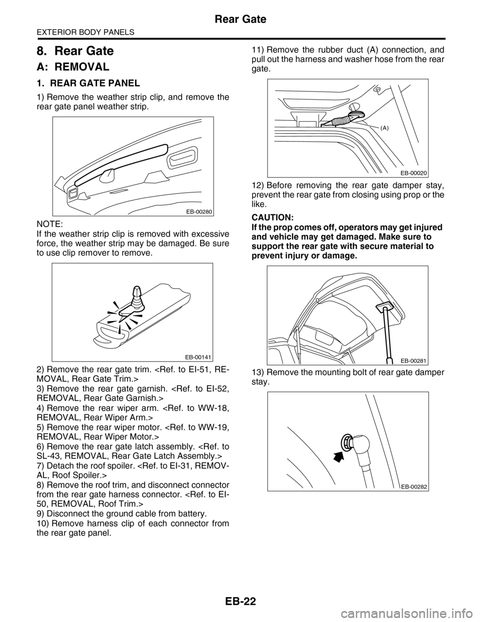
1) Remove the weather strip clip, and remove the
rear gate panel weather strip.
NOTE:
If the weather strip clip is removed with excessive
force, the weather strip may be damaged. Be sure
to use clip remover to remove.
2) Remove the rear gate trim.
3) Remove the rear gate garnish.
4) Remove the rear wiper arm.
5) Remove the rear wiper motor.
6) Remove the rear gate latch assembly.
7) Detach the roof spoiler.
8) Remove the roof trim, and disconnect connector
from the rear gate harness connector.
9) Disconnect the ground cable from battery.
10) Remove harness clip of each connector from
the rear gate panel.
11) Remove the rubber duct (A) connection, and
pull out the harness and washer hose from the rear
gate.
12) Before removing the rear gate damper stay,
prevent the rear gate from closing using prop or the
like.
CAUTION:
If the prop comes off, operators may get injured
and vehicle may get damaged. Make sure to
support the rear gate with secure material to
prevent injury or damage.
13) Remove the mounting bolt of rear gate damper
stay.
EB-00280
EB-00141
(A)
EB-00020
EB-00281
EB-00282
Page 272 of 2453
EI-30
Cowl Panel
EXTERIOR/INTERIOR TRIM
8. Cowl Panel
A: REMOVAL
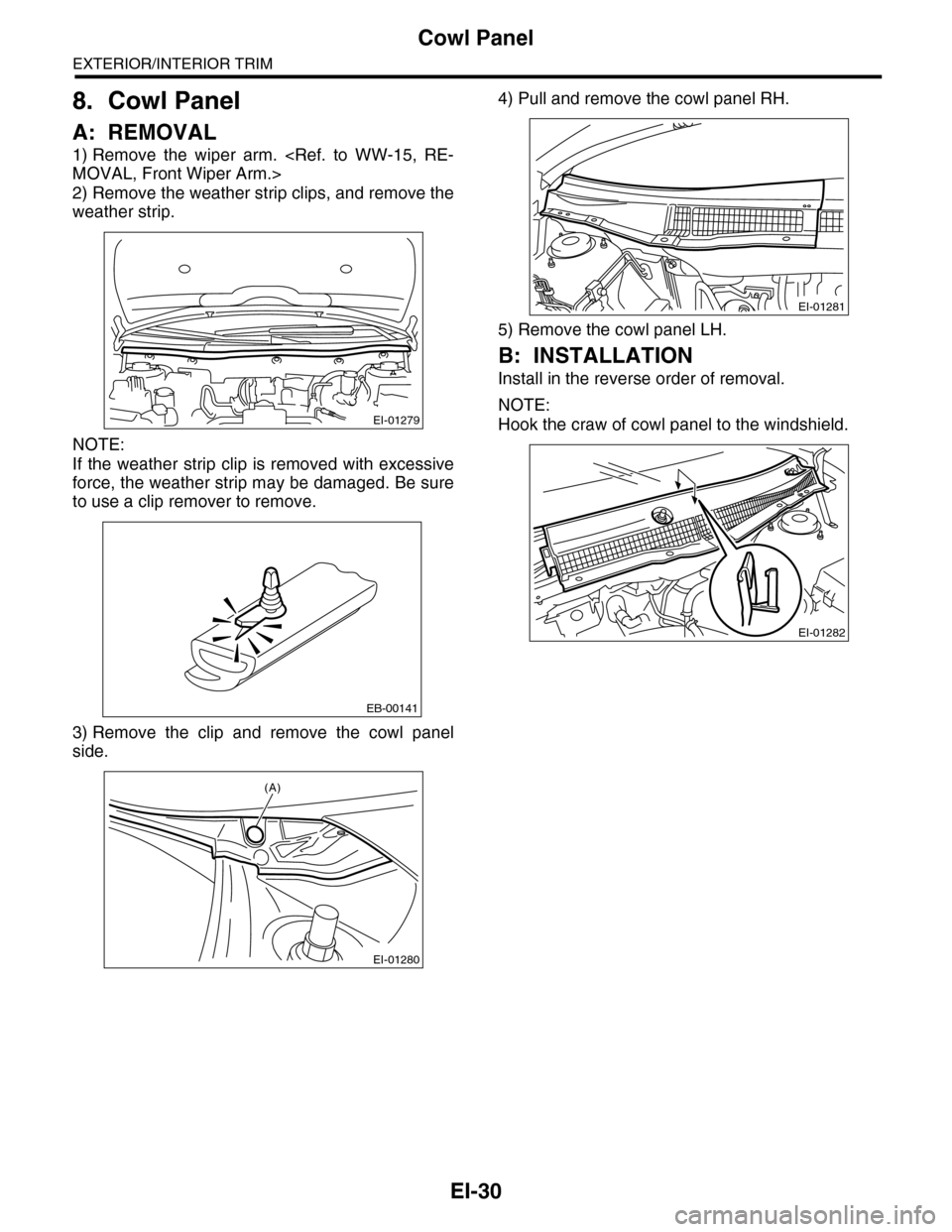
1) Remove the wiper arm.
2) Remove the weather strip clips, and remove the
weather strip.
NOTE:
If the weather strip clip is removed with excessive
force, the weather strip may be damaged. Be sure
to use a clip remover to remove.
3) Remove the clip and remove the cowl panel
side.
4) Pull and remove the cowl panel RH.
5) Remove the cowl panel LH.
B: INSTALLATION
Install in the reverse order of removal.
NOTE:
Hook the craw of cowl panel to the windshield.EI-01279
EB-00141
EI-01280
(A)
EI-01281
EI-01282
Page 317 of 2453
GW-22
Rear Gate Glass
GLASS/WINDOWS/MIRRORS
15.Rear Gate Glass
A: REMOVAL
1) Remove the rear wiper motor.
2) Disconnect the electrical connectors from rear
defogger terminal.
3) Remove the glass in the same procedure as for
windshield glass.
B: INSTALLATION
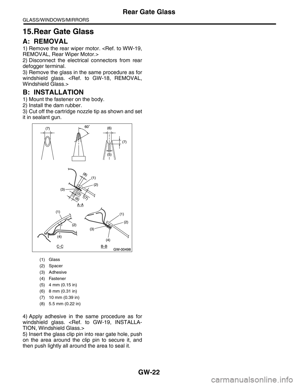
1) Mount the fastener on the body.
2) Install the dam rubber.
3) Cut off the cartridge nozzle tip as shown and set
it in sealant gun.
4) Apply adhesive in the same procedure as for
windshield glass.
5) Insert the glass clip pin into rear gate hole, push
on the area around the clip pin to secure it, and
then push lightly all around the area to seal it.
(1) Glass
(2) Spacer
(3) Adhesive
(4) Fastener
(5) 4 mm (0.15 in)
(6) 8 mm (0.31 in)
(7) 10 mm (0.39 in)
(8) 5.5 mm (0.22 in)
Page 318 of 2453
GW-23
Rear Gate Glass
GLASS/WINDOWS/MIRRORS
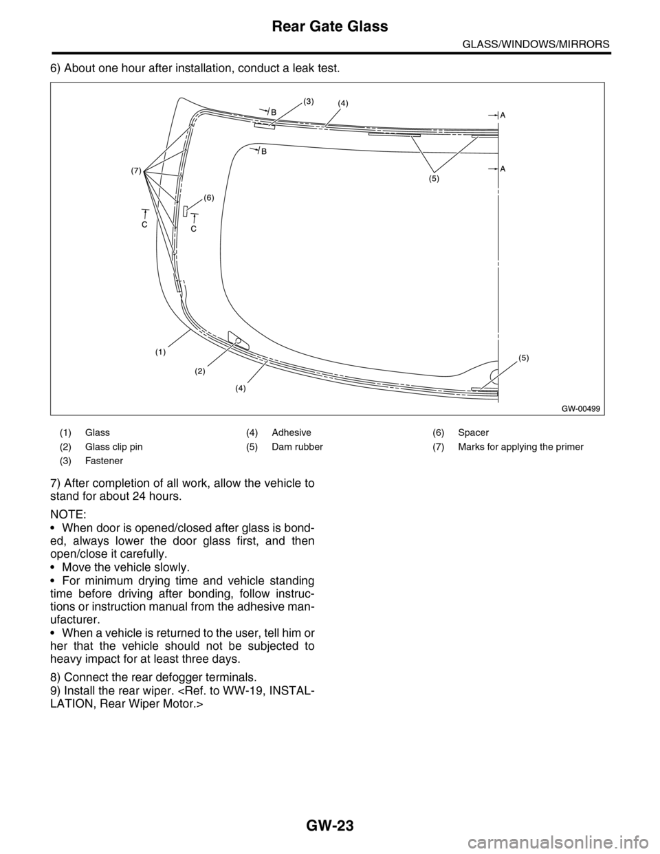
6) About one hour after installation, conduct a leak test.
7) After completion of all work, allow the vehicle to
stand for about 24 hours.
NOTE:
•When door is opened/closed after glass is bond-
ed, always lower the door glass first, and then
open/close it carefully.
•Move the vehicle slowly.
•For minimum drying time and vehicle standing
time before driving after bonding, follow instruc-
tions or instruction manual from the adhesive man-
ufacturer.
•When a vehicle is returned to the user, tell him or
her that the vehicle should not be subjected to
heavy impact for at least three days.
8) Connect the rear defogger terminals.
9) Install the rear wiper.
(1) Glass (4) Adhesive (6) Spacer
(2) Glass clip pin (5) Dam rubber (7) Marks for applying the primer
(3) Fastener
Page 325 of 2453
GW-30
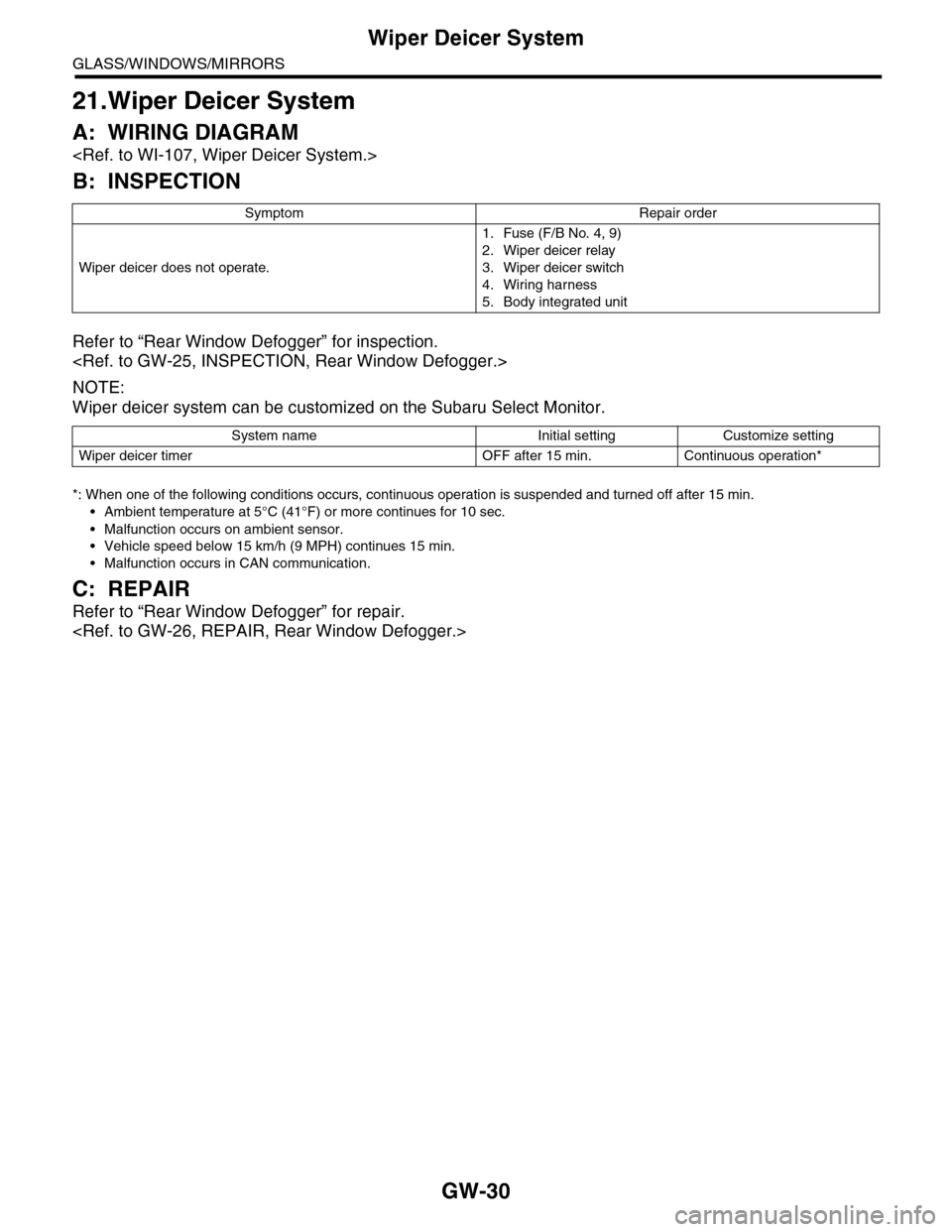
Wiper Deicer System
GLASS/WINDOWS/MIRRORS
21.Wiper Deicer System
A: WIRING DIAGRAM
B: INSPECTION
Refer to “Rear Window Defogger” for inspection.
NOTE:
Wiper deicer system can be customized on the Subaru Select Monitor.
*: When one of the following conditions occurs, continuous operation is suspended and turned off after 15 min.
•Ambient temperature at 5°C (41°F) or more continues for 10 sec.
•Malfunction occurs on ambient sensor.
•Vehicle speed below 15 km/h (9 MPH) continues 15 min.
•Malfunction occurs in CAN communication.
C: REPAIR
Refer to “Rear Window Defogger” for repair.
Symptom Repair order
Wiper deicer does not operate.
1. Fuse (F/B No. 4, 9)
2. Wiper deicer relay
3. Wiper deicer switch
4. Wiring harness
5. Body integrated unit
System name Initial setting Customize setting
Wiper deicer timer OFF after 15 min. Continuous operation*
Page 326 of 2453
GW-31
Wiper Deicer Switch
GLASS/WINDOWS/MIRRORS
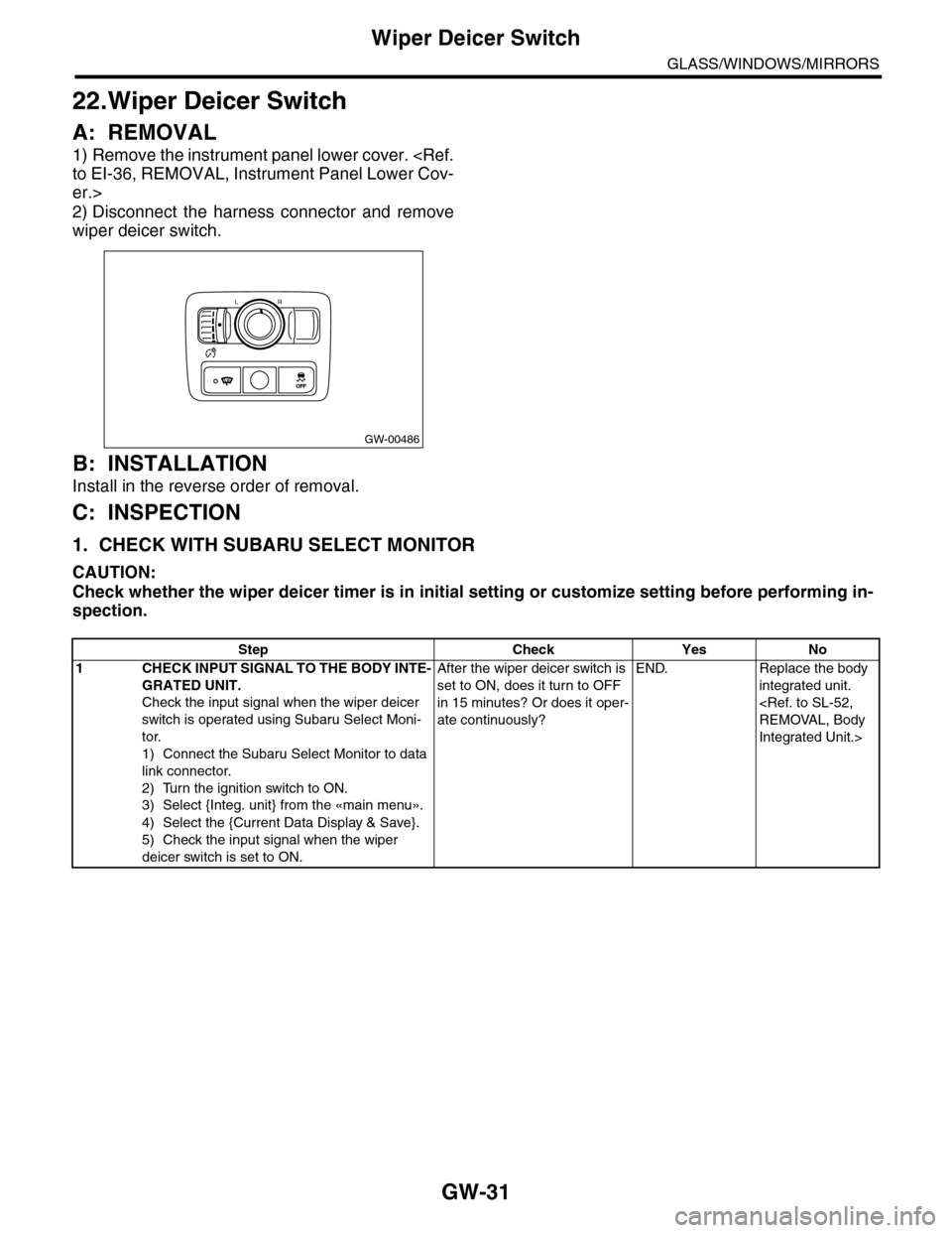
22.Wiper Deicer Switch
A: REMOVAL
1) Remove the instrument panel lower cover.
er.>
2) Disconnect the harness connector and remove
wiper deicer switch.
B: INSTALLATION
Install in the reverse order of removal.
C: INSPECTION
1. CHECK WITH SUBARU SELECT MONITOR
CAUTION:
Check whether the wiper deicer timer is in initial setting or customize setting before performing in-
spection.
GW-00486
LR
OFFOFF
Step Check Yes No
1CHECK INPUT SIGNAL TO THE BODY INTE-
GRATED UNIT.
Check the input signal when the wiper deicer
switch is operated using Subaru Select Moni-
tor.
1) Connect the Subaru Select Monitor to data
link connector.
2) Turn the ignition switch to ON.
3) Select {Integ. unit} from the «main menu».
4) Select the {Current Data Display & Save}.
5) Check the input signal when the wiper
deicer switch is set to ON.
After the wiper deicer switch is
set to ON, does it turn to OFF
in 15 minutes? Or does it oper-
ate continuously?
END. Replace the body
integrated unit.
Integrated Unit.>
Page 327 of 2453
GW-32
Wiper Deicer Switch
GLASS/WINDOWS/MIRRORS
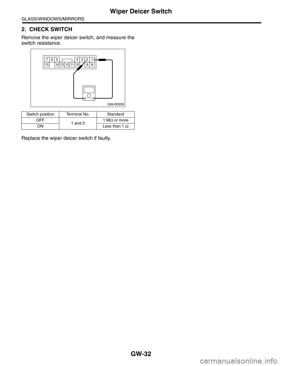
2. CHECK SWITCH
Remove the wiper deicer switch, and measure the
switch resistance.
Replace the wiper deicer switch if faulty.
Switch position Terminal No. Standard
OFF1 and 21 MΩ or more
ON Less than 1 Ω
GW-00330
914
7654321
81311101512
Page 460 of 2453
LAN(diag)-4
Check List for Interview
LAN SYSTEM (DIAGNOSTICS)
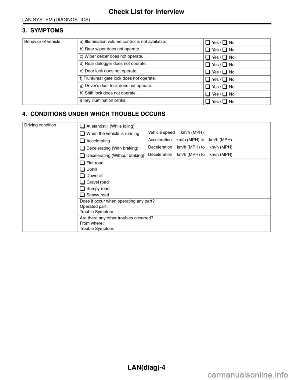
3. SYMPTOMS
4. CONDITIONS UNDER WHICH TROUBLE OCCURS
Behavior of vehicle a) Illumination volume control is not available. Yes / No
b) Rear wiper does not operate. Yes / No
c) Wiper deicer does not operate. Yes / No
d) Rear defogger does not operate. Yes / No
e) Door lock does not operate. Yes / No
f) Trunk/rear gate lock does not operate. Yes / No
g) Driver’s door lock does not operate. Yes / No
h) Shift lock does not operate. Yes / No
i) Key illumination blinks. Yes / No
Driving condition At standstill (While idling)
When the vehicle is runningVe h i c l e s p e e d k m / h ( M P H )
AcceleratingAcceleration km/h (MPH) to km/h (MPH)
Decelerating (With braking)Deceleration km/h (MPH) to km/h (MPH)
Decelerating (Without braking)Deceleration km/h (MPH) to km/h (MPH)
Flat road
Uphill
Downhill
Gravel road
Bumpy road
Snowy road
Does it occur when operating any part?
Operated part:
Tr o u b l e S y m p t o m :
Are there any other troubles occurred?
Fr o m wh er e :
Tr o u b l e S y m p t o m :
Page 466 of 2453
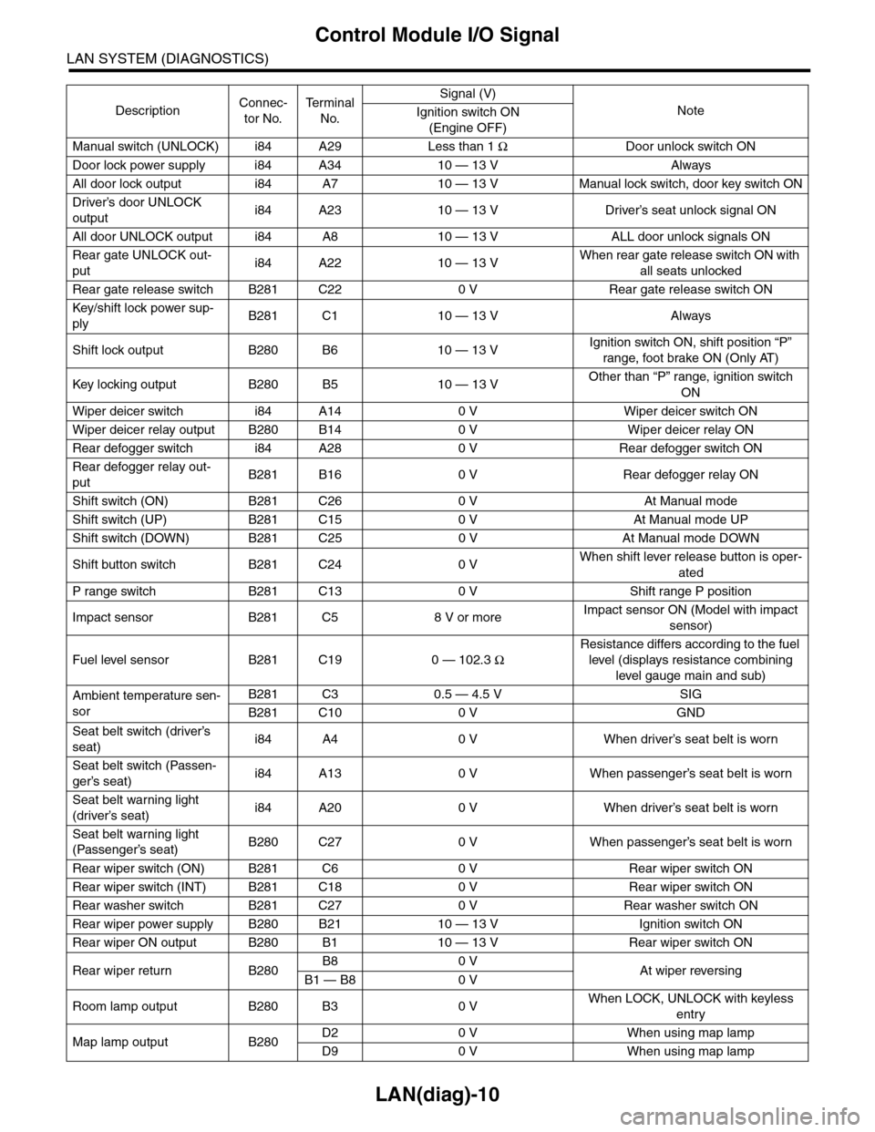
LAN(diag)-10
Control Module I/O Signal
LAN SYSTEM (DIAGNOSTICS)
Manual switch (UNLOCK) i84 A29 Less than 1 ΩDoor unlock switch ON
Door lock power supply i84 A34 10 — 13 V Always
All door lock output i84 A7 10 — 13 V Manual lock switch, door key switch ON
Driver’s door UNLOCK
outputi84 A23 10 — 13 V Driver’s seat unlock signal ON
All door UNLOCK output i84 A8 10 — 13 V ALL door unlock signals ON
Rear gate UNLOCK out-
puti84 A22 10 — 13 VWhen rear gate release switch ON with
all seats unlocked
Rear gate release switch B281 C22 0 V Rear gate release switch ON
Key/shift lock power sup-
plyB281 C1 10 — 13 V Always
Shift lock output B280 B6 10 — 13 VIgnition switch ON, shift position “P”
range, foot brake ON (Only AT)
Key locking output B280 B5 10 — 13 VOther than “P” range, ignition switch
ON
Wiper deicer switch i84 A14 0 V Wiper deicer switch ON
Wiper deicer relay output B280 B14 0 V Wiper deicer relay ON
Rear defogger switch i84 A28 0 V Rear defogger switch ON
Rear defogger relay out-
putB281 B16 0 V Rear defogger relay ON
Shift switch (ON) B281 C26 0 V At Manual mode
Shift switch (UP) B281 C15 0 V At Manual mode UP
Shift switch (DOWN) B281 C25 0 V At Manual mode DOWN
Shift button switch B281 C24 0 VWhen shift lever release button is oper-
ated
P range switch B281 C13 0 V Shift range P position
Impact sensor B281 C5 8 V or moreImpact sensor ON (Model with impact
sensor)
Fuel level sensor B281 C19 0 — 102.3 Ω
Resistance differs according to the fuel
level (displays resistance combining
level gauge main and sub)
Ambient temperature sen-
sor
B281 C3 0.5 — 4.5 V SIG
B281 C10 0 V GND
Seat belt switch (driver’s
seat)i84 A4 0 V When driver’s seat belt is worn
Seat belt switch (Passen-
ger’s seat)i84 A13 0 V When passenger’s seat belt is worn
Seat belt warning light
(driver’s seat)i84 A20 0 V When driver’s seat belt is worn
Seat belt warning light
(Passenger’s seat)B280 C27 0 V When passenger’s seat belt is worn
Rear wiper switch (ON) B281 C6 0 V Rear wiper switch ON
Rear wiper switch (INT) B281 C18 0 V Rear wiper switch ON
Rear washer switch B281 C27 0 V Rear washer switch ON
Rear wiper power supply B280 B21 10 — 13 V Ignition switch ON
Rear wiper ON output B280 B1 10 — 13 V Rear wiper switch ON
Rear wiper return B280B8 0 VAt wiper reversingB1 — B8 0 V
Room lamp output B280 B3 0 VWhen LOCK, UNLOCK with keyless
entry
Map lamp output B280D2 0 V When using map lamp
D9 0 V When using map lamp
DescriptionConnec-
tor No.
Te r m i n a l
No.
Signal (V)
NoteIgnition switch ON
(Engine OFF)
Page 470 of 2453
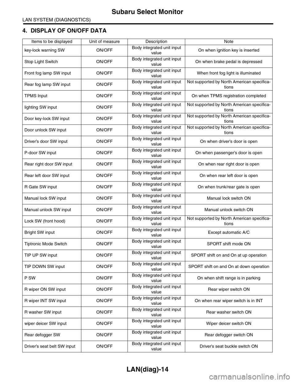
LAN(diag)-14
Subaru Select Monitor
LAN SYSTEM (DIAGNOSTICS)
4. DISPLAY OF ON/OFF DATA
Items to be displayed Unit of measure Description Note
key-lock warning SW ON/OFFBody integrated unit input
valueOn when ignition key is inserted
Stop Light Switch ON/OFFBody integrated unit input
valueOn when brake pedal is depressed
Fr o nt fog la mp S W i n pu t O N/O FFBody integrated unit input
valueWhen front fog light is illuminated
Rear fog lamp SW input ON/OFFBody integrated unit input
value
Not supported by North American specifica-
tions
TPMS Input ON/OFFBody integrated unit input
valueOn when TPMS registration completed
lighting SW input ON/OFFBody integrated unit input
value
Not supported by North American specifica-
tions
Door key-lock SW input ON/OFFBody integrated unit input
value
Not supported by North American specifica-
tions
Door unlock SW input ON/OFFBody integrated unit input
value
Not supported by North American specifica-
tions
Driver’s door SW input ON/OFFBody integrated unit input
valueOn when driver’s door is open
P-door SW input ON/OFFBody integrated unit input
valueOn when passenger’s door is open
Rear right door SW input ON/OFFBody integrated unit input
valueOn when rear right door is open
Rear left door SW input ON/OFFBody integrated unit input
valueOn when rear left door is open
R Gate SW input ON/OFFBody integrated unit input
valueOn when trunk/rear gate is open
Manual lock SW input ON/OFFBody integrated unit input
valueManual lock switch ON
Manual unlock SW input ON/OFFBody integrated unit input
valueManual unlock switch ON
Lock SW (front hood) ON/OFFBody integrated unit input
value
Not supported by North American specifica-
tions
Bright SW input ON/OFFBody integrated unit input
valueExcept automatic A/C
Tiptronic Mode Switch ON/OFFBody integrated unit input
valueSPORT shift mode ON
TIP UP SW input ON/OFFBody integrated unit input
valueSPORT shift on and On at up operation
TIP DOWN SW input ON/OFFBody integrated unit input
valueSPORT shift on and On at down operation
P SW ON/OFFBody integrated unit input
valueOn when shift range is in parking
R wiper ON SW input ON/OFFBody integrated unit input
valueRear wiper switch ON
R wiper INT SW input ON/OFFBody integrated unit input
valueOn when rear wiper switch is in INT
R washer SW input ON/OFFBody integrated unit input
valueRear washer switch ON
wiper deicer SW input ON/OFFBody integrated unit input
valueWiper deicer switch ON
Rear defogger SW ON/OFFBody integrated unit input
valueRear defogger switch ON
Driver’s seat belt SW input ON/OFFBody integrated unit input
valueDriver’s seat buckle switch ON