SUBARU TRIBECA 2014 1.G Owners Manual
Manufacturer: SUBARU, Model Year: 2014, Model line: TRIBECA, Model: SUBARU TRIBECA 2014 1.GPages: 426, PDF Size: 6.37 MB
Page 171 of 426
3-38Instruments and controls
NOTE
The outside mirror defogger also oper-ates while the rear window defogger isoperating.
Mirrors
Always check that the inside and outsidemirrors are properly adjusted before youstart driving.
&Type A inside mirror (if
equipped)
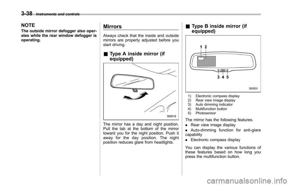
The mirror has a day and night position.Pull the tab at the bottom of the mirrortoward you for the night position. Push itaway for the day position. The nightposition reduces glare from headlights.
&Type B inside mirror (if
equipped)
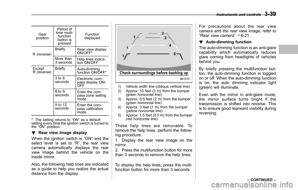
1) Electronic compass display2) Rear view image display3) Auto dimming indicator4) Multifunction button5) Photosensor
The mirror has the following features.
.Rear view image display
.Auto-dimming function for anti-glarecapability
.Electronic compass display
You can display the various functions ofthese features based on how long youpress the multifunction button.
Page 172 of 426
Gearposition
Period oftime multi-functionbutton ispressed
Functiondisplayed
R (reverse)
BrieflyRear view displayON/OFF*
More than3 secondsHelp lines indica-tion ON/OFF
ExceptR (reverse)BrieflyAuto-dimmingfunction ON/OFF*
3 to 6secondsElectronic com-pass display ON/OFF
6 to 9secondsEnterthe com-pass zone settingmode
9 to 12secondsEnter the com-passcalibrationmode
*: The setting returns to“ON”as a defaultsetting every time theignition switch is turned tothe“ON”position.
!Rear view image display
When the ignition switch is“ON”and theselect lever is set to“R”, the rear viewcamera automatically displays the rearview image behind the vehicle on theinside mirror.
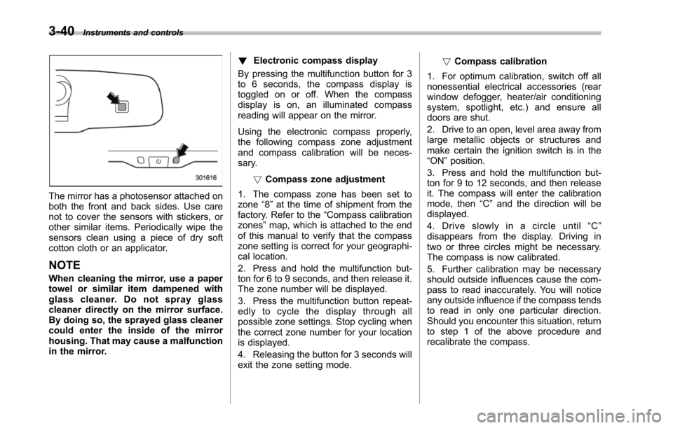
Also, the following help lines are indicatedas a guide to help you realize the actualdistance from the display.
1) Vehicle width line (oblique vertical line)2) Approx. 10 feet (3 m) from the bumper(green horizontal line)3) Approx. 6.5 feet (2 m) from the bumper(green horizontal line)4) Approx. 3 feet (1 m) from the bumper(yellow horizontal line)5) Approx. 1.5 feet (0.5 m) from the bumper(red horizontal line)
These help lines are removable. Toremove the help lines, perform the follow-ing procedure.
1. Display the rear view image on themirror.
2. Press the multifunction button for morethan 3 seconds to remove the help lines.
To display the help lines, press the multi-function button for more than 3 seconds.
For precautions about the rear viewcamera and the rear view image, refer to“Rear view camera”F6-21.
!Auto-dimming function
The auto-dimming function is an anti-glarecapability which automatically reducesglare coming from headlights of vehiclesbehind you.
By briefly pressing the multifunction but-ton, the auto-dimming function is toggledon or off. When the auto-dimming functionis on, the auto dimming indicator light(green) will illuminate.
Even with the mirror in anti-glare mode,the mirror surface turns bright if thetransmissionis shifted into reverse. Thisis to ensure good rearward visibility duringreversing.
Instruments and controls3-39
–CONTINUED–
Page 173 of 426
3-40Instruments and controls
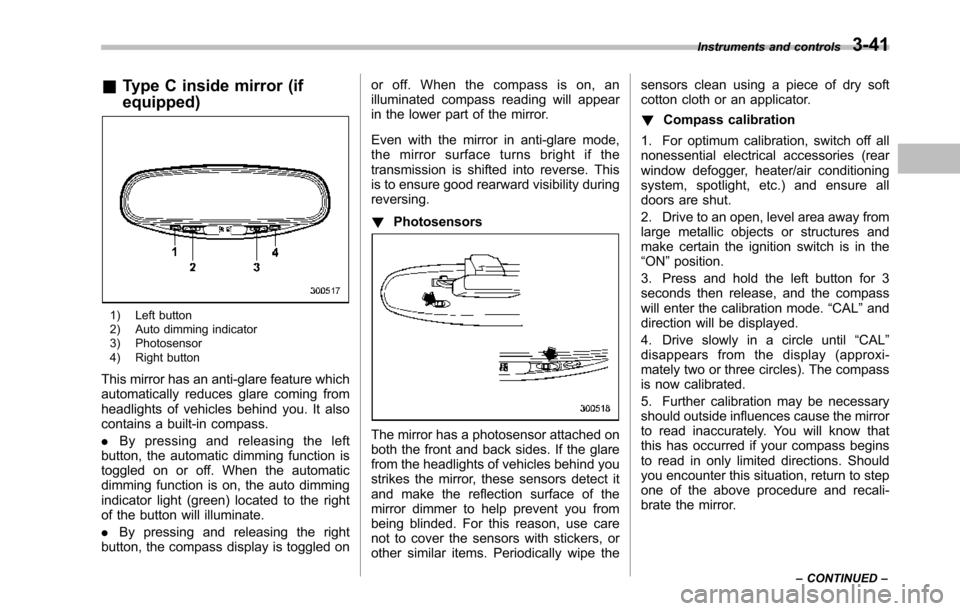
The mirror has a photosensor attached onboththe front and back sides. Use carenot to cover the sensors with stickers, orother similar items. Periodically wipe thesensors clean using a piece of dry softcotton cloth or an applicator.
NOTE
When cleaning the mirror, use a papertowel or similar item dampened withglass cleaner. Do not spray glasscleaner directly on the mirror surface.By doing so, the sprayed glass cleanercould enter the inside of the mirrorhousing. That may cause a malfunctionin the mirror.
!Electronic compass display
By pressing the multifunction button for 3to 6 seconds, the compass display istoggled on or off. When the compassdisplay is on, an illuminated compassreading will appear on the mirror.
Using the electronic compass properly,the following compass zone adjustmentand compass calibration will be neces-sary.
!Compasszone adjustment
1. The compass zone has been set tozone“8”at the time of shipment from thefactory. Refer to the“Compass calibrationzones”map, which is attached to the endof this manual to verify that the compasszone setting is correct for your geographi-cal location.
2. Press and hold the multifunction but-ton for 6 to 9 seconds, and then release it.The zone number will be displayed.
3. Press the multifunction button repeat-edly to cycle the display through allpossible zone settings. Stop cycling whenthe correct zone number for your locationis displayed.
4. Releasing the button for 3 seconds willexitthe zone setting mode.
!Compass calibration
1. For optimum calibration, switch off allnonessential electrical accessories (rearwindow defogger, heater/air conditioningsystem, spotlight, etc.) and ensure alldoors are shut.
2. Drive to an open, level area away fromlarge metallic objects or structures andmake certain the ignition switch is in the“ON”position.
3. Press and hold the multifunction but-ton for 9 to 12 seconds, and then releaseit. The compass will enter the calibrationmode,then“C”and the direction will bedisplayed.
4. Drive slowly in a circle until“C”disappears from the display. Driving intwo or three circles might be necessary.The compass is now calibrated.
5. Further calibration may be necessaryshould outside influences cause the com-pass to read inaccurately. You will noticeany outside influence if the compass tendsto read in only one particular direction.Shouldyou encounter this situation, returnto step 1 of the above procedure andrecalibrate the compass.
Page 174 of 426
&Type C inside mirror (if
equipped)
1) Left button2) Auto dimming indicator3) Photosensor4) Right button
This mirror has an anti-glare feature whichautomatically reduces glare coming fromheadlights of vehicles behind you. It alsocontains a built-in compass.
.By pressing and releasing the leftbutton, the automatic dimming function istoggled on or off. When the automaticdimming function is on, the auto dimmingindicator light (green) located to the rightof the button will illuminate.
.By pressing and releasing the rightbutton, the compass display is toggled on
or off. When the compass is on, anilluminated compass reading will appearin the lower part of the mirror.
Even with the mirror in anti-glare mode,the mirror surface turns bright if thetransmission is shifted into reverse. Thisis to ensure good rearward visibility duringreversing.
!Photosensors
The mirror has a photosensor attached onboth the front and back sides. If the glarefrom the headlights of vehicles behind youstrikes the mirror, these sensors detect itand make the reflection surface of themirror dimmer to help prevent you frombeing blinded. For this reason, use carenot to cover the sensors with stickers, orother similar items. Periodically wipe the
sensors clean using a piece of dry softcotton cloth or an applicator.
!Compass calibration
1. For optimum calibration, switch off allnonessential electrical accessories (rearwindow defogger, heater/air conditioningsystem, spotlight, etc.) and ensure alldoors are shut.
2. Drive to an open, level area away fromlarge metallic objects or structures andmake certain the ignition switch is in the“ON”position.
3. Press and hold the left button for 3seconds then release, and the compasswill enter the calibration mode.“CAL”anddirection will be displayed.
4. Drive slowly in a circle until“CAL”disappears from the display (approxi-mately two or three circles). The compassis now calibrated.
5. Further calibration may be necessaryshould outside influences cause the mirrorto read inaccurately. You will know thatthis has occurred if your compass beginsto read in only limited directions. Shouldyou encounter this situation, return to stepone of the above procedure and recali-brate the mirror.
Instruments and controls3-41
–CONTINUED–
Page 175 of 426
3-42Instruments and controls
!Compass zone adjustment
1. The zone setting is factory preset toZone 8. Refer to the“Compass calibrationzone”map attached to the end of thismanual to verify that the compass zonesetting is correct for your geographicallocation.
2. Press and hold the right button for 3seconds then release, and the word“ZONE”will briefly appear and then thezone number will be displayed.
3. Press the right-hand button repeatedlyto cycle the display through all possiblezone settings. Stop cycling when thecorrect zone setting for your location isdisplayed.
4. Releasing the button for 3 seconds willexit the zone setting mode.
&Outside mirrors
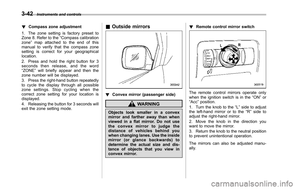
!Convex mirror (passenger side)
WARNING
Objects look smaller in a convexmirror and farther away than whenviewed in a flat mirror. Do not usethe convex mirror to judge thedistance of vehicles behind youwhen changing lanes. Use the insidemirror (or glance backwards) todetermine the actual size and dis-tance of objects that you view inconvex mirror.
!Remote control mirror switch
The remote control mirrors operate onlywhen the ignition switch is in the“ON”or“Acc”position.
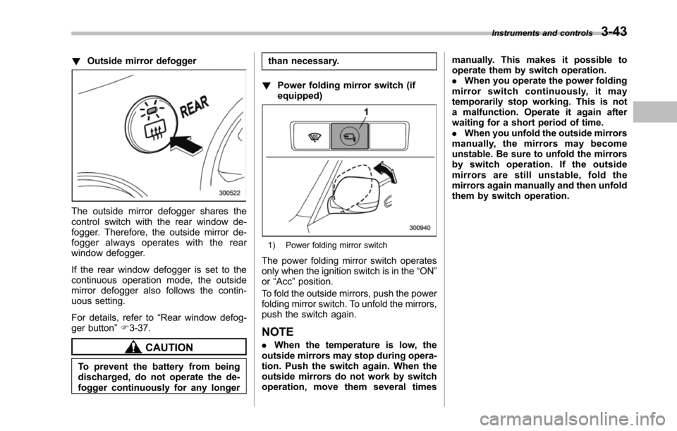
1. Turn the knob to the“L”side to adjustthe left-hand mirror or to the“R”side toadjust the right-hand mirror.
2. Move the knob in the direction youwant to move the mirror.
3. Return the knob to the neutral positionto prevent unintentional operation.
The mirrors can also be adjusted manu-ally.
Page 176 of 426
!Outside mirror defogger
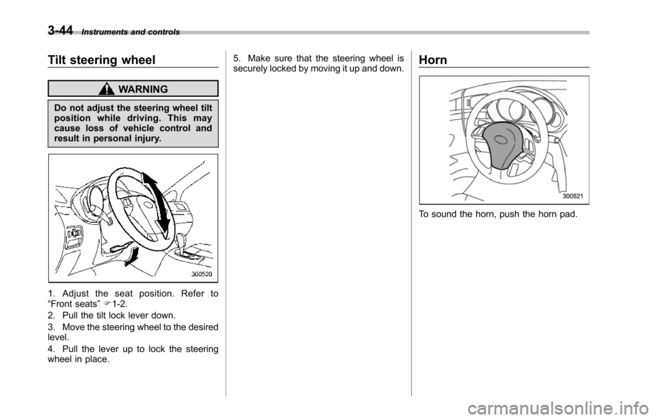
The outside mirror defogger shares thecontrol switch with the rear window de-fogger. Therefore, the outside mirror de-fogger always operates with the rearwindow defogger.
If the rear window defogger is set to thecontinuous operation mode, the outsidemirror defogger also follows the contin-uous setting.
For details, refer to“Rear window defog-ger button”F3-37.
CAUTION
To prevent the battery from beingdischarged, do not operate the de-fogger continuously for any longer
than necessary.
!Power folding mirror switch (ifequipped)
1) Power folding mirror switch
The power folding mirror switch operatesonly when the ignition switch is in the“ON”or“Acc”position.
To fold the outside mirrors, push the powerfolding mirror switch. To unfold the mirrors,push the switch again.
NOTE
.When the temperature is low, theoutside mirrorsmay stop during opera-tion. Push the switch again. When theoutside mirrors do not work by switchoperation, move them several times
manually. This makes it possible tooperate them by switch operation..When you operate the power foldingmirror switch continuously, it maytemporarily stop working. This is nota malfunction. Operate it again afterwaiting for a short period of time..When you unfold the outside mirrorsmanually, the mirrors may becomeunstable. Be sure to unfold the mirrorsby switch operation. If the outsidemirrors are still unstable, fold themirrors again manually and then unfoldthem by switch operation.
Instruments and controls3-43
Page 177 of 426
3-44Instruments and controls
Tilt steering wheel
WARNING
Do not adjust the steering wheel tiltposition while driving. This maycause loss of vehicle control andresult in personal injury.
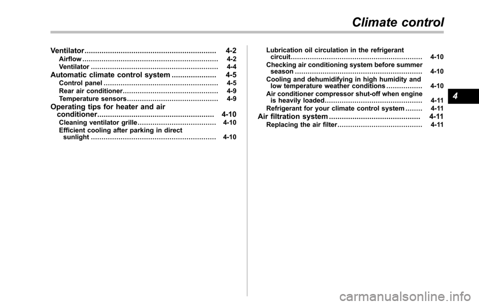
1. Adjust the seat position. Refer to“Front seats”F1-2.
2. Pull the tilt lock lever down.
3. Move the steering wheel to the desiredlevel.
4. Pull the lever up to lock the steeringwheel in place.
5. Make sure that the steering wheel issecurely locked by moving it up and down.Horn
To sound the horn, push the horn pad.
Page 178 of 426
Ventilator.............................................................. 4-2Airflow................................................................ 4-2Ventilator............................................................ 4-4
Automatic climate control system..................... 4-5Control panel...................................................... 4-5Rear air conditioner............................................. 4-9Temperature sensors........................................... 4-9
Operating tips for heater and airconditioner....................................................... 4-10Cleaning ventilator grille..................................... 4-10Efficient cooling after parking in directsunlight........................................................... 4-10
Lubrication oil circulation in the refrigerantcircuit.............................................................. 4-10Checking air conditioning system before summerseason............................................................ 4-10Cooling and dehumidifying in high humidity andlow temperature weather conditions................. 4-10Air conditioner compressor shut-off when engineis heavily loaded.............................................. 4-11Refrigerant for your climate control system ........ 4-11
Air filtration system........................................... 4-11Replacing the air filter........................................ 4-11
Climate control
4
Page 179 of 426
4-2Climate control
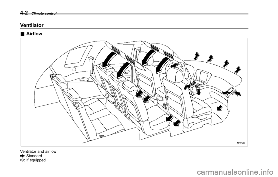
Ventilator
&Airflow
Ventilator and airflow: Standard: If equipped
Page 180 of 426
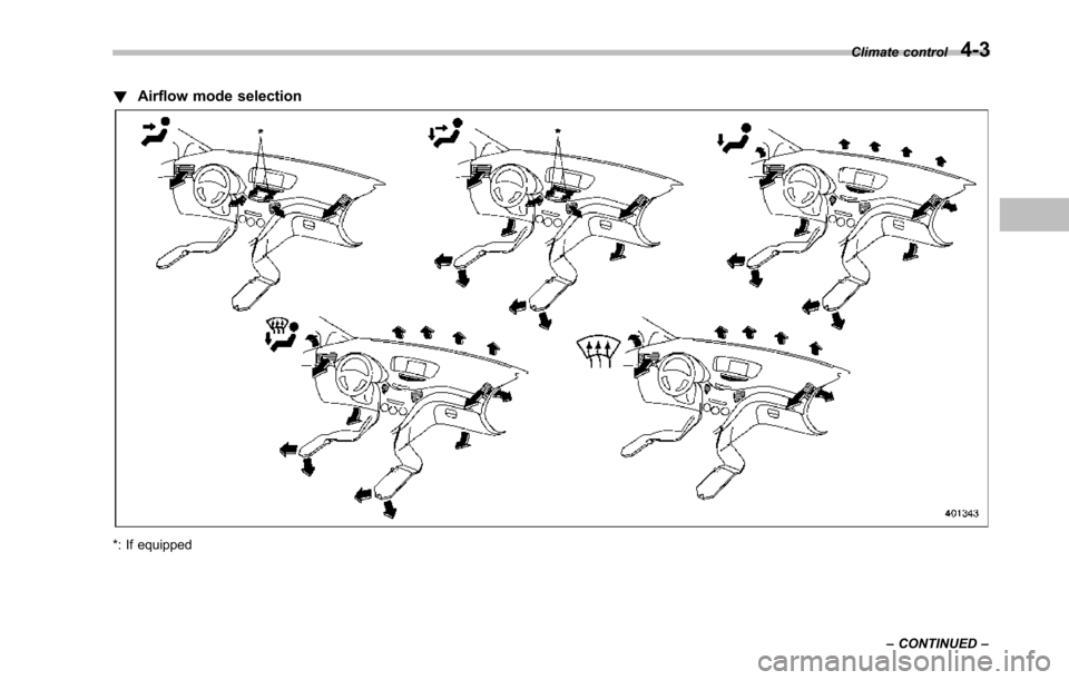
!Airflow mode selection
*: If equipped
Climate control4-3
–CONTINUED–