SUZUKI GRAND VITARA 1987 Service Repair Manual
Manufacturer: SUZUKI, Model Year: 1987, Model line: GRAND VITARA, Model: SUZUKI GRAND VITARA 1987Pages: 962, PDF Size: 27.87 MB
Page 141 of 962

With vacuum pump gauge set at Black side of
VTV, when pump is operated, pointer moves
considerably but moves back to zero position as
soon as pump operation is stopped.
Brown side
(Actuator side) Black side
Fig. 4-l-60
1. VTV
2. Vacuum pump gauge
install VTV. Refer to Fig. 4-l -2 for installation.
[ VSV (Vacuum Switching Valve)]
1) Disconnect VSV vacuum hoses from 3 way
joint and secondary actuator and while
blowing either hose, check that air doesn’t
come out of the other hose.
2) Turn on ignition switch and depress accelera-
tor pedal fully. 5 or 6 seconds later, while
blowing either vacuum hose, check that air
comes out of the other hose.
J5
Fig. 4- l-61
1I
1. vsv4. WOTS
2. Ignition switch5. ECM
3. Battery6. Blow air
If check results in steps 1) and 2)are not satisfac-
tory, either replace VSV or check WOTS and its
circuit referring to SECTION5 “EMISSION
CONTROL SYSTEM”.
Idle Speed Adjustment
NOTE:
Before starting engine, place transmission gear
shift lever in “Neutral”, and set parking brake
and block drive wheels.
Before idle speed check and adjustment, make
sure of the following.
l Lead wires and hoses of engine emission
control systems are connected securely.
l Accelerator cable has some play, that is, it is
not tight.
l All vacuum hoses are connected securely.
l Fuel level should be within round mark at the
center of level gauge.
l Valve lash is checked and adjusted according
to the maintenance schedule.
l Air cleaner has been properly installed and is
in good condition.
l All accessories (wipers, heater, lights, etc) are
out of service.
l Ignition timing is within specification.
l Idle up actuator is not operating when engine
is running at idle speed.
NOTE:
In areas above 4,00Ofeet( 1,220m) elevation
(high altitude), idle up system will be normally
in operation. Do not attempt to adjust the idle
speed.
After above items are all confirmed, adjust idle
speed as follows.
1) Warm up engine to normal operating tempe-
rature.
2) Check to ensure that idle speed is within
750 - 850 r/min (rpm).
3) If idle speed is not within specified range,
adjust by turning idle speed adjusting screw.
If idle speed can not be adjusted to the speci-
fication by turning the adjusting screw, it can
be due to faulty return of throttle valve or
some other reason. Determine cause and
repair, and then adjust idle speed to specifica-
tion.
4-26
Page 142 of 962

1. Idle speed adjusting screw
Fig. 4- l-62 Idle speed adjusting screw
4) After idle speed adjustment, check idle-up for
operation with lights (small light, tail light,
side marker light and license light), heater fan
and rear defogger (if equipped) turned “ON”,
only one at a time. Refer to item “Idle Up
Adjustment”. (p. 4-20).
5) Stop engine and check to ensure that accelera-
tor cable play is within the specification as
previously outlined. If play is out of specifica-
tion, adjust it.
Idle Mixture Inspection and Adjustment
[Inspection]
1) Warm up engine to normal operating tem-
perature.
2) Remove seal rubber of duty check coupler
and connect positive terminal of duty meter
to “Blue/Red” wire and negative terminal to
“Black/Green” wire.
1
1. Duty check
3) Set tachometer.
4) Run engine at 1,500 - 2,000 r/min for 30
seconds and bring it to idle speed.
5) Check duty at specified idle speed. If it is out
of specification, adjust it to specification ac-
cording to following adjustment procedure.
Specified DutyIO-50
at 750 - 850 r/min.
After inspection, install seal rubber to duty
check coupler.
[Idle Mixture Adjustment]
The carburetor has been calibrated at the facto-
ry and. should not normally need adjustment in
the field. For this reason, the mixture adjust-
ment should never be changed from the original
factory setting. However, if during diagnosis, the
check indicates the carburetor to be the cause of
a driver performance complaint or emission
failure, or the carburetor is overhauled or
replaced, the idle mixture can be adjusted using
the following procedure.
After adjustment, mixture adjusting screw pin
must be installed.
Idle mixture adjustment procedure is as follows:
1) Remove carburetor from intake manifold
following normal service procedure to gain
access to mixture adjusting screw pin covering
mixture adjusting screw.
2) Drive out mixture adjusting screw pin using
about 4.5 mm (0.18 in) thick iron rod as
shown below.
1. Mixture adjusting screw pin2. Rod
Fig. 4- l-64 Mixture adjusting screw pin
2. Air intake case
Fig. 4- l-63
4-27
Page 143 of 962
3) Reinstall carburetor following normal service
procedures.
Connect emission control system hoses and
lead wires. Make specified play on accelerator
cable and refill cooling system.
4) Place transaxle gear shift lever in “Neutral”,
set parking brake and block drive wheels.
5) Start engine, and warm it up to normal
operating temperature, stop engine.
6) Be sure to check the following before idle
mixture adjustment.
l Fuel level is within round mark at the
center of level gauge.
l Valve lash is checked and adjusted accord-
ing to the maintenance schedule.
l Air cleaner has been properly installed
and is in good condition.
l All accessories (wipers, heater, lights etc)
are out of service.
l Ignition timing is within specification.
l Choke valve opens fully.
l Idle-up actuator does not operate.
7) Check and adjust idle speed to specification
if necessary.
8) Remove seal rubber of duty check coupler
and connect positive terminal of duty
meter to“Blue/Red” wire and negative
terminal to “Black/Green” wire.
9) Run engine at 1,500 - 2,000 r/min for 30
seconds and bring it to idle speed.
10) With engine running at idle speed, adjust idle
mixture adjusting screw slowly in small incre-
ment allowing time for duty to stabilize after
turning screw to obtain duty of 10 - 50.
If duty is too low, back screw out; if too
high, screw it in. After obtaining duty of
10 - 50, recheck idle speed, and adjust if
necessary.
NOTE:
If adjustment can’t be made because duty meter
indicator does not deflect, check feed back
system according to the checking procedure of
system described in section of Emission Control
System.
11) After adjustment, install seal rubber to duty
check coupler and drive in idle mixture
adjusting screw pin.
4-28
Page 144 of 962

4-2. AIR CLEANER
GENERAL DESCRIPTION
In the air cleaner case, a dry-type air cleaner element is provided for filtering.out dirt and dust from air
being drawn into the engine for combustion.
A damaged element must be replaced with a new one, since it allows dust particles to enter the engine if
used as it is. Such dust particles could cause wear to the engine inner parts and this further results in
decreased output.
Also, the element must be cleaned periodically. Dusty and dirty element causes decrease in output and
increase in fuel consumption. The dusty element even after cleaning should be replaced with a new one.
Fig. 4-2-l
1. Air cleaner case
2. Air cleaner case cap
3. Air cleaner element4. Air cleaner inlet hose
5. Air cleaner outlet hose
6. Warm air hose
7. Carburetor air intake case
8. Check valve
9. Therm0 sensor (valve)10. Air control actuator
MAINTENANCE SERVICES
Air Cleaner Element
[Cleaning]
1) Remove air cleaner outlet hose and case cap.
Fig. 4-2-21. Air cleaner outlet hose2. Air cleaner case cap3. Clamp
4-29
Page 145 of 962
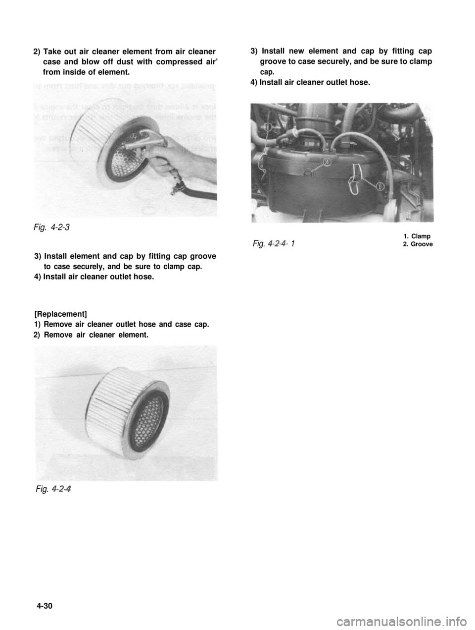
2) Take out air cleaner element from air cleaner
case and blow off dust with compressed air’
from inside of element.
3) Install new element and cap by fitting cap
groove to case securely, and be sure to clamp
cap.
4) Install air cleaner outlet hose.
Fig. 4-2-3
Fig. 4-2-4- 1
1. Clamp2. Groove
3) Install element and cap by fitting cap groove
to case securely, and be sure to clamp cap.
4) Install air cleaner outlet hose.
[Replacement]
1) Remove air cleaner outlet hose and case cap.
2) Remove air cleaner element.
Fig. 4-2-4
4-30
Page 146 of 962
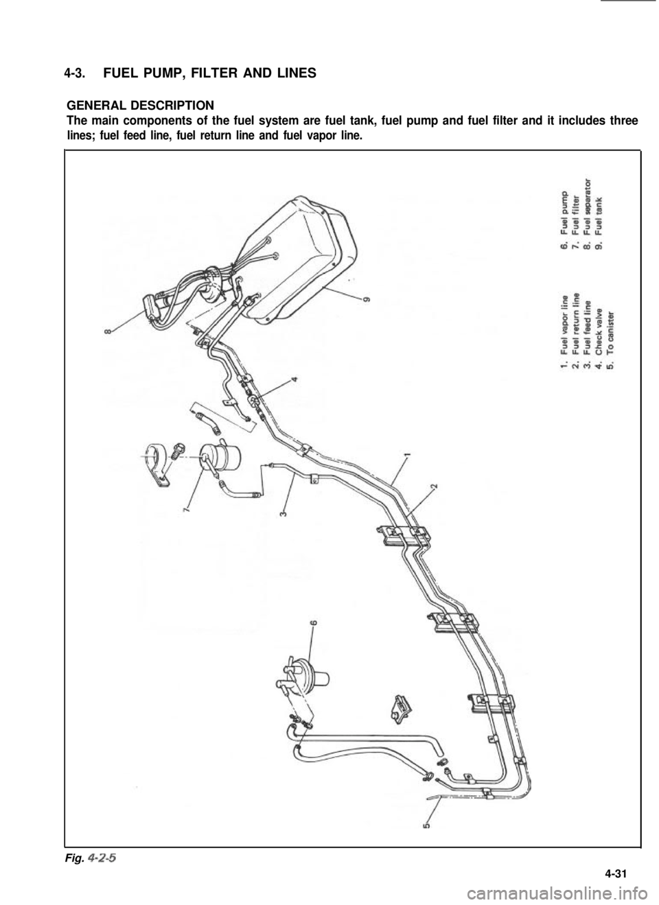
4-3.FUEL PUMP, FILTER AND LINES
GENERAL DESCRIPTION
The main components of the fuel system are fuel tank, fuel pump and fuel filter and it includes three
lines; fuel feed line, fuel return line and fuel vapor line.
Fig. 4-Z-5
4-31
Page 147 of 962
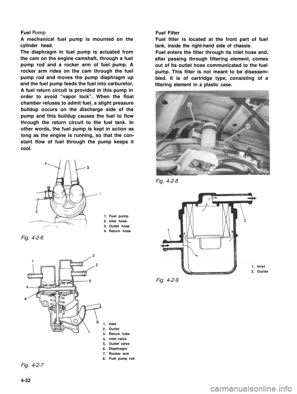
Fuel Pulp
A mechanical fuel pump is mounted on the
cylinder head.
The diaphragm in fuel pump is actuated from
the cam on the engine camshaft, through a fuel
pump rod and a rocker arm of fuel pump. A
rocker arm rides on the cam through the fuel
pump rod and moves the pump diaphragm up
and the fuel pump feeds the fuel into carburetor.
A fuel return circuit is provided in this pump in
order to avoid “vapor lock”. When the float
chamber refuses to admit fuel, a slight pressure
buildup occurs on the discharge side of the
pump and this buildup causes the fuel to flow
through the return circuit to the fuel tank. In
other words, the fuel pump is kept in action as
long as the engine is running, so that the con-
stant flow of fuel through the pump keeps it
cool.
2
Fig. 4-2-8
Fig. 4-2-6
Fuel Filter
Fuel filter is located at the front part of fuel
tank, inside the right-hand side of chassis.
Fuel enters the filter through its inlet hose and,
after passing through filtering element, comes
out of its outlet hose communicated to the fuel
pump. This filter is not meant to be disassem-
bled. It is of cartridge type, consisting of a
filtering element in a plastic case.
1
1. Fuel pump
2. inlet hose
3. Outlet hose4. Return hose
6
1. Inlet
2. Outlet
Fig. 4-2-9
1.Inlet
2.Outlet
3.Return tube
4.inlet valve
5.Outlet valve
6.Diaphragm
7.Rocker arm
8.Fuel pump rod
Fig. 4-2-7
4-32
Page 148 of 962
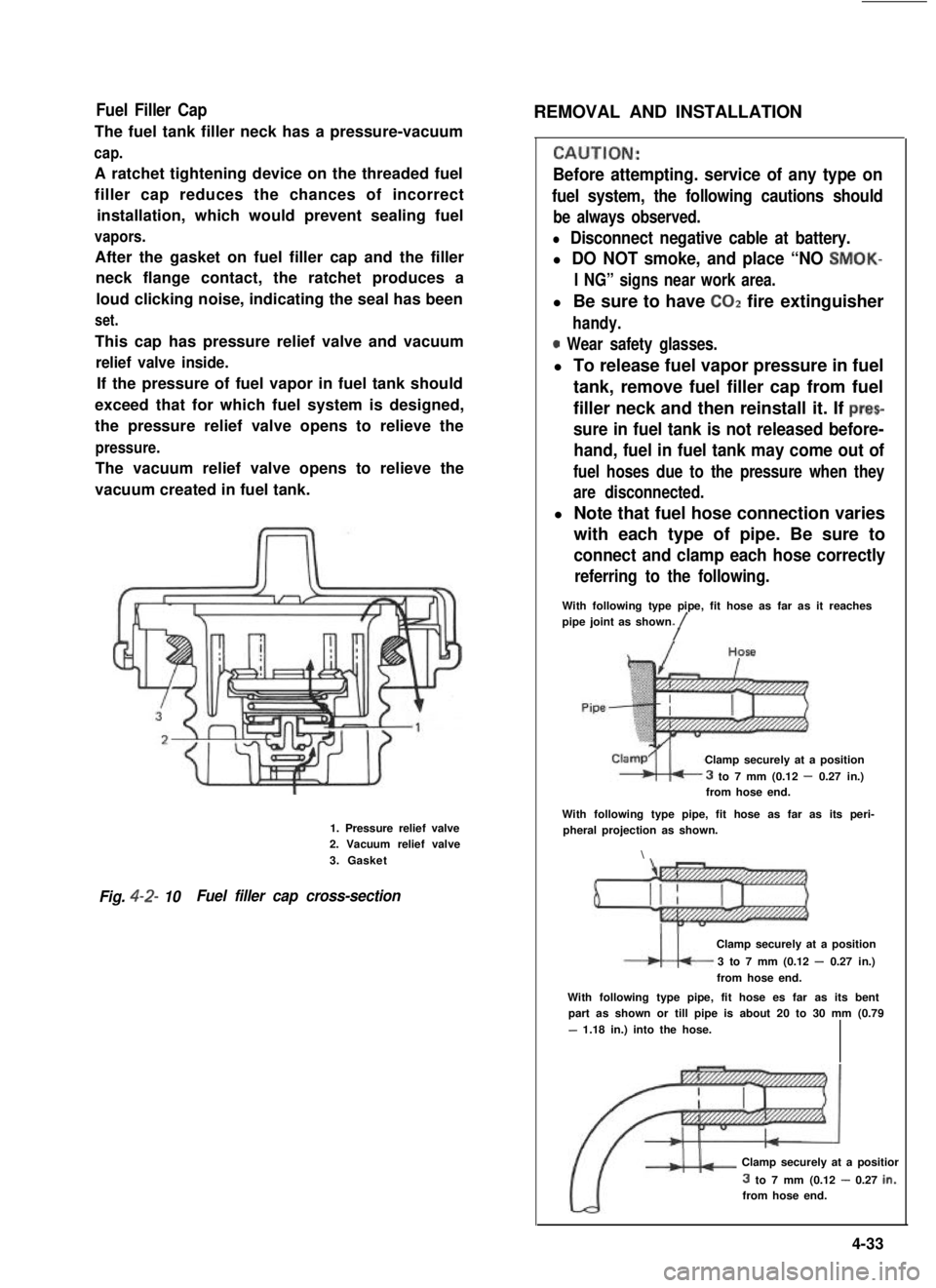
Fuel Filler Cap
The fuel tank filler neck has a pressure-vacuum
cap.
A ratchet tightening device on the threaded fuel
filler cap reduces the chances of incorrect
installation, which would prevent sealing fuel
vapors.
After the gasket on fuel filler cap and the filler
neck flange contact, the ratchet produces a
loud clicking noise, indicating the seal has been
set.
This cap has pressure relief valve and vacuum
relief valve inside.
If the pressure of fuel vapor in fuel tank should
exceed that for which fuel system is designed,
the pressure relief valve opens to relieve the
pressure.
The vacuum relief valve opens to relieve the
vacuum created in fuel tank.
1. Pressure relief valve2. Vacuum relief valve
3. Gasket
Fig. 4-2- 10Fuel filler cap cross-section
REMOVAL AND INSTALLATION
CALJTION:
Before attempting. service of any type on
fuel system, the following cautions should
be always observed.
l Disconnect negative cable at battery.
l DO NOT smoke, and place “NO SMOK-
I NG” signs near work area.
l Be sure to have COZ fire extinguisher
handy.
0 Wear safety glasses.
l To release fuel vapor pressure in fuel
tank, remove fuel filler cap from fuel
filler neck and then reinstall it. If prec
sure in fuel tank is not released before-
hand, fuel in fuel tank may come out of
fuel hoses due to the pressure when they
are disconnected.
l Note that fuel hose connection varies
with each type of pipe. Be sure to
connect and clamp each hose correctly
referring to the following.
With following type pipe, fit hose as far as it reachespipe joint as shown./
Clamp securely at a position
3 to 7 mm (0.12 - 0.27 in.)from hose end.
With following type pipe, fit hose as far as its peri-pheral projection as shown.
\
Clamp securely at a position
3 to 7 mm (0.12 - 0.27 in.)
from hose end.
With following type pipe, fit hose es far as its bentpart as shown or till pipe is about 20 to 30 mm (0.79
- 1.18 in.) into the hose.
Clamp securely at a positior
3 to 7 mm (0.12 - 0.27 in.:from hose end.
4-33
Page 149 of 962
![SUZUKI GRAND VITARA 1987 Service Repair Manual ,Fuel Pump
[ Rem’oval]
1) Disconnect negative cable from battery.
2) Remove fuel filler cap from fuel filler neck to
release fuel vapor pressure in fuel tank. After
releasing, reinstall the cap.
3) SUZUKI GRAND VITARA 1987 Service Repair Manual ,Fuel Pump
[ Rem’oval]
1) Disconnect negative cable from battery.
2) Remove fuel filler cap from fuel filler neck to
release fuel vapor pressure in fuel tank. After
releasing, reinstall the cap.
3)](/img/20/57437/w960_57437-148.png)
,Fuel Pump
[ Rem’oval]
1) Disconnect negative cable from battery.
2) Remove fuel filler cap from fuel filler neck to
release fuel vapor pressure in fuel tank. After
releasing, reinstall the cap.
3) Disconnect fuel inlet, outlet and return hoses
from fuel pump.
Fuel Filter
[Removal]
1) Disconnect negative cable from battery.
2) Remove fuel filler cap to release fuel vapor
pressure in fuel tank. After releasing, reinstall
the cap.
3) Disconnect inlet and outlet hoses from fuel
filter.
4) Remove fuel filter with clamp.
[Installation]
1) Install filter and clamp, and connect inlet
and outlet hoses to fuel filter.
NOTE:.
The top connection is for outlet hose, the
lower one for inlet hose.
1. Fuel pump
2. Inlet hose3. Outlet hose
4. Return hose
Fig. 4-2-l 1
4) Remove fuel pump from cylinder head.
5) Remove fuel pump rod from cylinder head.
2
1. Fuel pump rod
2. Cylinder head
[Installation]
Reverse removal procedure for installation
using care for the following.
l After oiling it,install fuel pump rod to
cylinder head.
0 Use new fuel pump gasket.
l Make sure for proper hose connection.
0 Upon completion of installation, start engine
and check fuel hose or its joints for leaks.
1.Fuel filter3.From fueltank
2.To fuel pump4.Clamp
Fig.4-2-13
2) Connect negative cable to battery.
3) After installation, start engine and check it
for leaks.
Fuel Tank
[Removal]
1) Disconnect negative cable from battery.
2) Disconnect fuel level gauge lead wire.
3) To release the pressure in fuel tank, remove
fuel filler cap and then, reinstall it.
4) Raise car on hoist.
5) Drain fuel by removing drain plug.
6) Remove filler hose protector.
7) Disconnect filler hose from fuel tank.
.8) Disconnect fuel hosesand pipe from fuel tank.
9) Remove fuel tank.
4-34
Page 150 of 962
![SUZUKI GRAND VITARA 1987 Service Repair Manual [Fuel tank purging procedure]
WARNING:
This purging procedure will NOT remove
all fuel vapor. Do not attempt any repair
on tank where heat or flame is required, as
an explosion resulting in personal i SUZUKI GRAND VITARA 1987 Service Repair Manual [Fuel tank purging procedure]
WARNING:
This purging procedure will NOT remove
all fuel vapor. Do not attempt any repair
on tank where heat or flame is required, as
an explosion resulting in personal i](/img/20/57437/w960_57437-149.png)
[Fuel tank purging procedure]
WARNING:
This purging procedure will NOT remove
all fuel vapor. Do not attempt any repair
on tank where heat or flame is required, as
an explosion resulting in personal injury
cou Id occur.J
The following procedure is used for purging the
fuel tank.
1) After removing fuel tank, remove all hoses,
fuel level gauge from fuel tank.
2) Drain all remaining fuel from tank.
3) Move tank to flushing area.
4) Fill tank with warm water or tap water, and
agitate vigorously and drain. Repeat this
washing until inside of tank is clean.
Replace tank if inside is rusty.
5) Completely flush out remaining water after
washing.
[ Installation]
Reverse removal procedure for installation using
care for the following.
Tightening torque30-45 Nm
for fuel tank(3.0- 4.5 kg-m)
drain plug(22.0 - 32.5 lb-ft)
Refer to Fig. 4-2-5 for piping and clamp posi-
tions.
l Make sure for correct hose-to-pipe connec-
tion.
l Clamp hoses securely.
l Upon completion of installation, start engine
and check hose joints for leaks.
MAINTENANCE SERVICES
Fuel Lines
Visually inspect fuel lines and connections for
evidence of fuel leakage, hose cracking, and
damage. Make sure all clamps are secure.
Repair leaky joints, if any.
Replace hoses that are suspected of being crack-
ed.
Fig. 4-2-14
Fuel Filler (tank) Cap
Visually inspect gasket of fuel filler cap.
If it is damaged or deteriorated, replace filler cap
with new one.
NOTE:
If cap requires replacement, only a cap with
the same features should be used. Failure to
use correct cap can result in a serious malfunc-
tion of the system.
Fig. 4-2-15
1. Fuel filler cap
2. Fuel filler capgasket
Fuel Filter
As said before, this filter does not permit dis-
assembly: it is to be replaced with a new one
periodically.
Replace fuel filter referring to previous item of
“Fuel Filter Removal and Installation”.
This servicing must be performed in a well
ventilated area and away from any open
flames (such as gas hot water heaters).
4-35