4 wheel drive SUZUKI GRAND VITARA 2018 Owners Manual
[x] Cancel search | Manufacturer: SUZUKI, Model Year: 2018, Model line: GRAND VITARA, Model: SUZUKI GRAND VITARA 2018Pages: 482, PDF Size: 21 MB
Page 37 of 482
2-15
BEFORE DRIVING
54P00-01E
68LM249
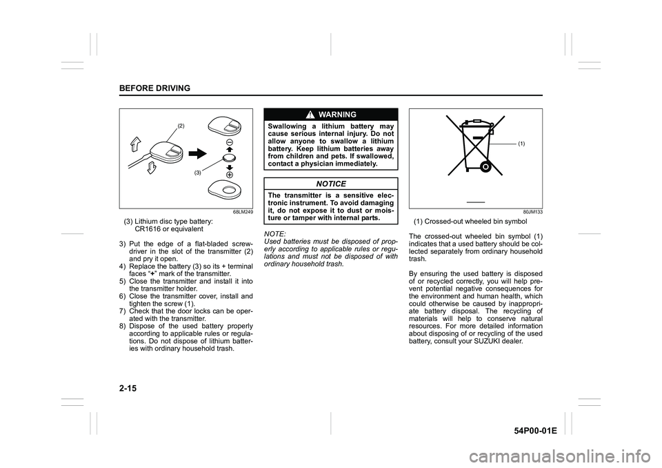
(3) Lithium disc type battery:
CR1616 or equivalent
3) Put the edge of a flat-bladed screw-
driver in the slot of the transmitter (2)
and pry it open.
4) Replace the battery (3) so its + terminal
faces “+” mark of the transmitter.
5) Close the transmitter and install it into
the transmitter holder.
6) Close the transmitter cover, install and
tighten the screw (1).
7) Check that the door locks can be oper-
ated with the transmitter.
8) Dispose of the used battery properly
according to applicable rules or regula-
tions. Do not dispose of lithium batter-
ies with ordinary household trash.NOTE:
Used batteries must be disposed of prop-
erly according to applicable rules or regu-
lations and must not be disposed of with
ordinary household trash.
80JM133
(1) Crossed-out wheeled bin symbol
The crossed-out wheeled bin symbol (1)
indicates that a used battery should be col-
lected separately from ordinary household
trash.
By ensuring the used battery is disposed
of or recycled correctly, you will help pre-
vent potential negative consequences for
the environment and human health, which
could otherwise be caused by inappropri-
ate battery disposal. The recycling of
materials will help to conserve natural
resources. For more detailed information
about disposing of or recycling of the used
battery, consult your SUZUKI dealer.
(2)
(3)
WA R N I N G
Swallowing a lithium battery may
cause serious internal injury. Do not
allow anyone to swallow a lithium
battery. Keep lithium batteries away
from children and pets. If swallowed,
contact a physician immediately.
NOTICE
The transmitter is a sensitive elec-
tronic instrument. To avoid damaging
it, do not expose it to dust or mois-
ture or tamper with internal parts.
(1)
Page 74 of 482
2-52
BEFORE DRIVING
54P00-01E
Therefore, an air bag is not a substitute for
seat belts. To maximize your protection,
always fasten your seat belts. Be aware
that no system can prevent all possible
injuries that may occur in an accident.
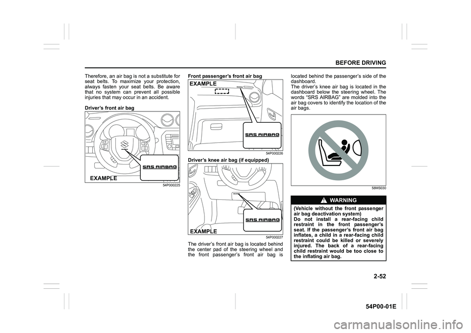
Driver’s front air bag
54P000225
Front passenger’s front air bag
54P000226
Driver’s knee air bag (if equipped)
54P000227
The driver’s front air bag is located behind
the center pad of the steering wheel and
the front passenger’s front air bag islocated behind the passenger’s side of the
dashboard.
The driver’s knee air bag is located in the
dashboard below the steering wheel. The
words “SRS AIRBAG” are molded into the
air bag covers to identify the location of the
air bags.
58MS030
EXAMPLE
EXAMPLE
EXAMPLE
WA R N I N G
(Vehicle without the front passenger
air bag deactivation system)
Do not install a rear-facing child
restraint in the front passenger’s
seat. If the passenger’s front air bag
inflates, a child in a rear-facing child
restraint could be killed or severely
injured. The back of a rear-facing
child restraint would be too close to
the inflating air bag.
Page 81 of 482
2-59
BEFORE DRIVING
54P00-01E
65D610
54G582
Even though your vehicle is moderately
damaged by a crash, it may not be severe
enough to trigger front, side or side curtain
air bags to inflate. If your vehicle sustains
any front-end or side damage, have the air
bag system inspected by an authorized
SUZUKI dealer to ensure that it works
properly.
Your vehicle is equipped with a diagnostic
module which records information about
the air bag system if the air bags deploy in
a crash. The module records information
about overall system status, and which
sensors activated the deployment.
Servicing the air bag system
If the air bags inflate, have the air bags
and related components replaced by an
authorized SUZUKI dealer as soon as pos-
sible.
If your vehicle ever gets in deep water and
the driver’s floor is submerged, the air bag
controller could be damaged. If this hap-
WA R N I N G
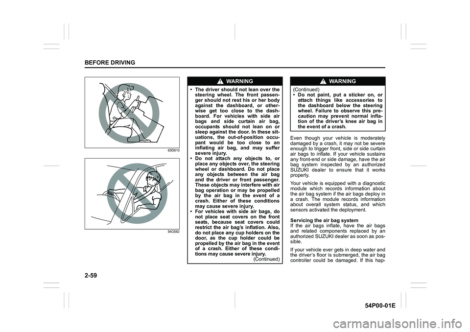
• The driver should not lean over the
steering wheel. The front passen-
ger should not rest his or her body
against the dashboard, or other-
wise get too close to the dash-
board. For vehicles with side air
bags and side curtain air bag,
occupants should not lean on or
sleep against the door. In these sit-
uations, the out-of-position occu-
pant would be too close to an
inflating air bag, and may suffer
severe injury.
• Do not attach any objects to, or
place any objects over, the steering
wheel or dashboard. Do not place
any objects between the air bag
and the driver or front passenger.
These objects may interfere with air
bag operation or may be propelled
by the air bag in the event of a
crash. Either of these conditions
may cause severe injury.
• For vehicles with side air bags, do
not place seat covers on the front
seats, because seat covers could
restrict the air bag’s inflation. Also,
do not place any cup holders on the
door, as the cup holder could be
propelled by the air bag in the event
of a crash. Either of these condi-
tions may cause severe injury.
(Continued)
WA R N I N G
(Continued)
• Do not paint, put a sticker on, or
attach things like accessories to
the dashboard below the steering
wheel. Failure to observe this pre-
caution may prevent normal infla-
tion of the driver’s knee air bag in
the event of a crash.
Page 111 of 482
2-89
BEFORE DRIVING
54P00-01E
Refer to “Tire pressure monitoring system
(TPMS) (if equipped)” in “OPERATING
YOUR VEHICLE” section for additional
details on the tire pressure monitoring sys-
tem. Refer to “Tires” in “INSPECTION AND
MAINTENANCE” section for information
on maintaining proper tire pressure.
WA R N I N G
The load-carrying capacity of your
tires is reduced at lower inflation
pressures. If your tires are even mod-
erately under-inflated, the load on the
tires may exceed the load-carrying
capacity of the tires, which could lead
to tire failure. The low tire pressure
warning light will not alert you to this
condition, because it only comes on
when one or more of your tires
becomes significantly under-inflated.
Check and adjust your tire inflation
pressure at least once a month. Refer
to “Tires” in “INSPECTION AND
MAINTENANCE” section.
WA R N I N G
Continuing to drive with the low tire
pressure warning light on can lead to
an accident, resulting in severe injury
or death.
If the low tire pressure warning light
comes on and stays on, reduce your
speed and avoid abrupt steering and
braking. Be aware that driving on a
significantly under-inflated tire can
cause the tire to overheat and can
lead to tire failure, and may affect
steering control and brake effective-
ness. Stop the vehicle in a safe place
as soon as possible and check your
tires.
• If you have a flat tire, replace it with
the spare tire (if equipped). Refer to
“Jacking instructions” in “EMER-
GENCY SERVICE” section for the
tire replacement method. Also refer
to “Replacing tires and/or wheels”
for instructions on how to restore
normal operation of the TPMS after
you have had a flat tire.
(Continued)
WA R N I N G
(Continued)
• If your vehicle is equipped with a
flat tire repair kit instead of a spare
tire, refer to “Flat tire repair kit (if
equipped)” in “EMERGENCY SER-
VICE” section for instructions on
how to perform an emergency
repair of a flat tire.
• If one or more of your tires is
under-inflated, adjust the inflation
pressure of all tires to the recom-
mended inflation pressure as soon
as possible.
Page 120 of 482
2-98
BEFORE DRIVING
54P00-01E
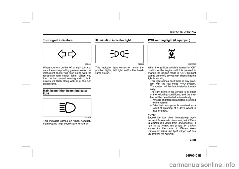
Turn signal indicators
50G055
When you turn on the left or right turn sig-
nals, the corresponding green arrow on the
instrument cluster will flash along with the
respective turn signal lights. When you
turn on the hazard warning switch, both
arrows will flash along with all of the turn
signal lights.
Main beam (high beam) indicator
light
50G056
This indicator comes on when headlight
main beams (high beams) are turned on.
Illumination indicator light
64J045
This indicator light comes on while the
position lights, tail light and/or the head-
lights are on.
4WD warning light (if equipped)
57L30042
When the ignition switch is turned to “ON”
position or the engine switch is pressed to
change the ignition mode to “ON”, this light
comes on briefly so you can check that the
light is working.
• This light comes on if there is any prob-
lem with the four-mode 4WD system.
The system will be deactivated automati-
cally.
• The light blinks if the vehicle is in either
of the following conditions, and the sys-
tem will be deactivated automatically.
– Wheels of different diameters are fitted
to the vehicle.
– Drive train components overheat as a
result of spinning of a drive wheel in
mud or snow.
NOTE:
Should the light blink, immediately move
the vehicle to a safe place and park it there
to protect the drive train components. If
you let the engine run at idle for a while
except for the case of different sized
wheels are fitted, the light will go out and
the system will resume.
Page 130 of 482
2-108
BEFORE DRIVING
54P00-01E
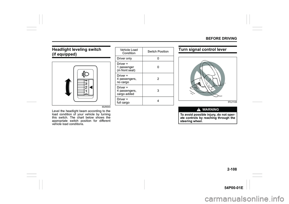
Headlight leveling switch
(if equipped)
80JM040
Level the headlight beam according to the
load condition of your vehicle by turning
this switch. The chart below shows the
appropriate switch position for different
vehicle load conditions.
Turn signal control lever
57L21128
Vehicle Load
ConditionSwitch Position
Driver only 0
Driver +
1 passenger
(in front seat)0
Driver +
4 passengers,
no cargo2
Driver +
4 passengers,
cargo added3
Driver +
full cargo4
WA R N I N G
To avoid possible injury, do not oper-
ate controls by reaching through the
steering wheel.
Page 132 of 482
2-110
BEFORE DRIVING
54P00-01E
Hazard warning switch
54P000242
Push in the hazard warning switch to acti-
vate the hazard warning lights. All turn sig-
nal lights and both turn signal indicators
will flash simultaneously. To turn off the
lights, push the switch again.
Use the hazard warning lights to warn
other drivers of possible risk of traffic haz-
ard when you park your vehicle in case of
emergency.
Windshield wiper and washer
lever
65D611
Wiper and washer operation
When the ignition switch is in “ON” position
or the ignition mode is “ON”, you can use
the wiper/washer lever or switch (if
equipped).
Windshield wipers
61MM0A079
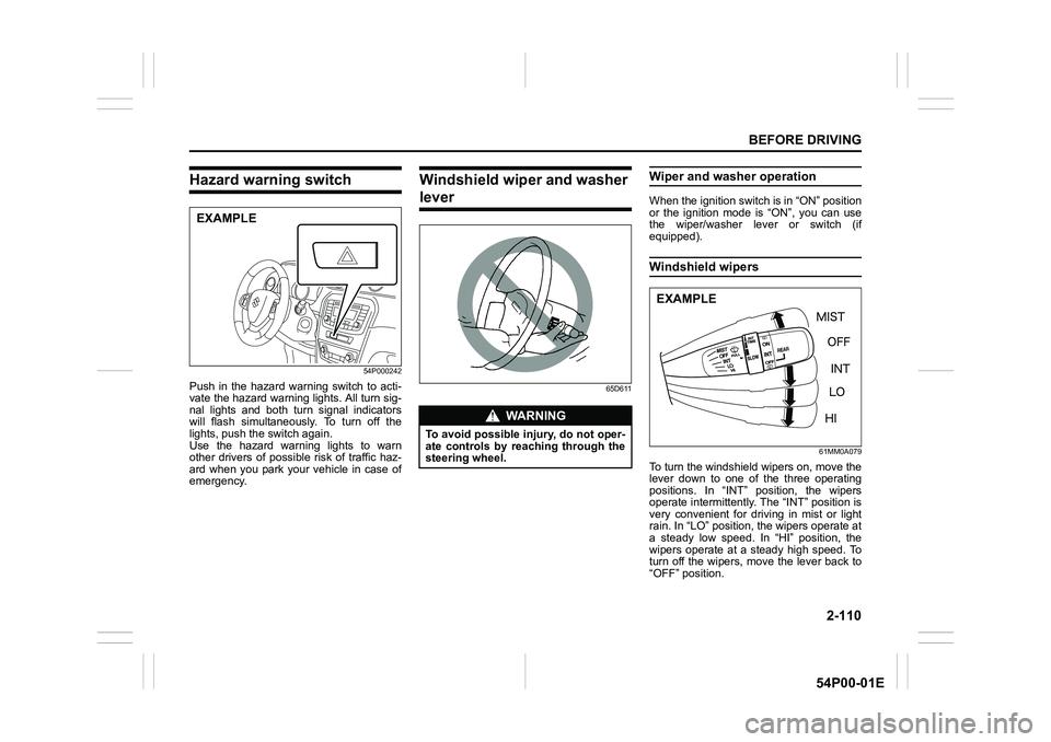
To turn the windshield wipers on, move the
lever down to one of the three operating
positions. In “INT” position, the wipers
operate intermittently. The “INT” position is
very convenient for driving in mist or light
rain. In “LO” position, the wipers operate at
a steady low speed. In “HI” position, the
wipers operate at a steady high speed. To
turn off the wipers, move the lever back to
“OFF” position.
EXAMPLE
WA R N I N G
To avoid possible injury, do not oper-
ate controls by reaching through the
steering wheel.
EXAMPLE
Page 143 of 482
3-3
OPERATING YOUR VEHICLE
54P00-01E
making it appear that the oil level has not
changed.
You should also be aware that the diluting
ingredients evaporate out when the vehicle
is subsequently driven at high speeds,
such as on an expressway, making it
appear that oil is excessively consumed
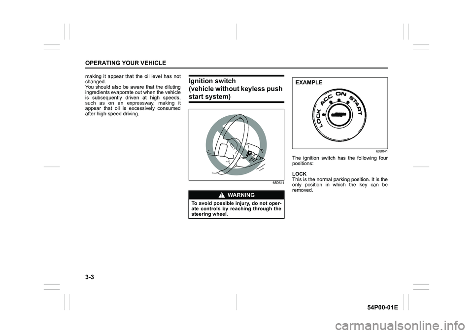
after high-speed driving.Ignition switch
(vehicle without keyless push
start system)
65D61160B041
The ignition switch has the following four
positions:
LOCK
This is the normal parking position. It is the
only position in which the key can be
removed.
WA R N I N G
To avoid possible injury, do not oper-
ate controls by reaching through the
steering wheel.
EXAMPLE
Page 144 of 482
3-4
OPERATING YOUR VEHICLE
54P00-01E
Manual transaxle
60G033
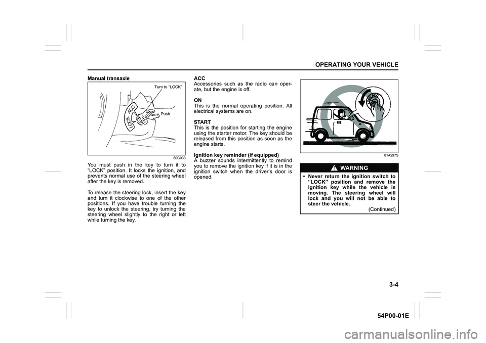
You must push in the key to turn it to
“LOCK” position. It locks the ignition, and
prevents normal use of the steering wheel
after the key is removed.
To release the steering lock, insert the key
and turn it clockwise to one of the other
positions. If you have trouble turning the
key to unlock the steering, try turning the
steering wheel slightly to the right or left
while turning the key.ACC
Accessories such as the radio can oper-
ate, but the engine is off.
ON
This is the normal operating position. All
electrical systems are on.
START
This is the position for starting the engine
using the starter motor. The key should be
released from this position as soon as the
engine starts.
Ignition key reminder (if equipped)
A buzzer sounds intermittently to remind
you to remove the ignition key if it is in the
ignition switch when the driver’s door is
opened.
81A297S
Turn to “LOCK”
Push
WA R N I N G
• Never return the ignition switch to
“LOCK” position and remove the
ignition key while the vehicle is
moving. The steering wheel will
lock and you will not be able to
steer the vehicle.
(Continued)
Page 146 of 482
3-6
OPERATING YOUR VEHICLE
54P00-01E
NOTE:
In the presence of strong radio signals or
noise, you may not be able to change the
ignition mode to “ACC” or “ON” or to start
the engine using the engine switch. In this
case, the information display in the instru-
ment cluster will show the following mes-
sage: KEY FOB NOT DETECTED.
Unreleased steering lock warning
If the steering lock remains engaged when
you press the engine switch to change the
ignition mode to “ON”, the information dis-
play in the instrument cluster shows the
message: “TRN. STEERING WHEEL TO
RELEASE LOCK”. Refer to “Information
display” in “BEFORE DRIVING” section for
details.
NOTE:
The steering lock may not be released if
some load is acting on the steering wheel.
If this happens, turn the steering wheel to
the right or left to relieve it from the load
before you press the engine switch again
to change to the desired ignition mode.
Keyless push start system
(if equipped)
Provided the keyless push start system
remote controller is within the interior work-
able area (refer to the related explanation
in this section), you can use the engine
switch for starting the engine and selecting
an ignition mode (“ACC” or “ON”). In addi-
tion, the following functions can be used:
• Keyless entry function. Refer to “Keyless
push start system remote controller /
keyless entry system transmitter” in
“BEFORE DRIVING” section for details.
• Locking and unlocking doors (including
the tailgate) using a request switch.
Refer to “Keyless push start system
remote controller / keyless entry system
transmitter” in “BEFORE DRIVING” sec-
tion for details.
• Immobilizer (anti-theft) function. Refer to
“Immobilizer system” in “BEFORE DRIV-
ING” section for details.
Engine switch illumination
The engine switch is illuminated (lit) in the
following situations:
• When the engine is off and the driver’s
door is open, or for 15 seconds after the
driver’s door is closed. The illumination
will fade out after 15 seconds passed.
NOTICE
Do not leave the engine switch in
“ACC” or “ON” mode when the
engine is not running. Avoid using
the radio or other electric accesso-
ries for a long time when the engine
switch is in “ACC” or “ON” mode
when the engine is not running, oth-
erwise the battery may discharge.