body SUZUKI JIMNY 2005 3.G Service Workshop Manual
[x] Cancel search | Manufacturer: SUZUKI, Model Year: 2005, Model line: JIMNY, Model: SUZUKI JIMNY 2005 3.GPages: 687, PDF Size: 13.38 MB
Page 635 of 687
Downloaded from www.Manualslib.com manuals search engine 6E-30 ENGINE AND EMISSION CONTROL SYSTEM
Throttle position sensor (TP sensor)
INSPECTION
1) Disconnect negative cable at battery and connector from TP
sensor.
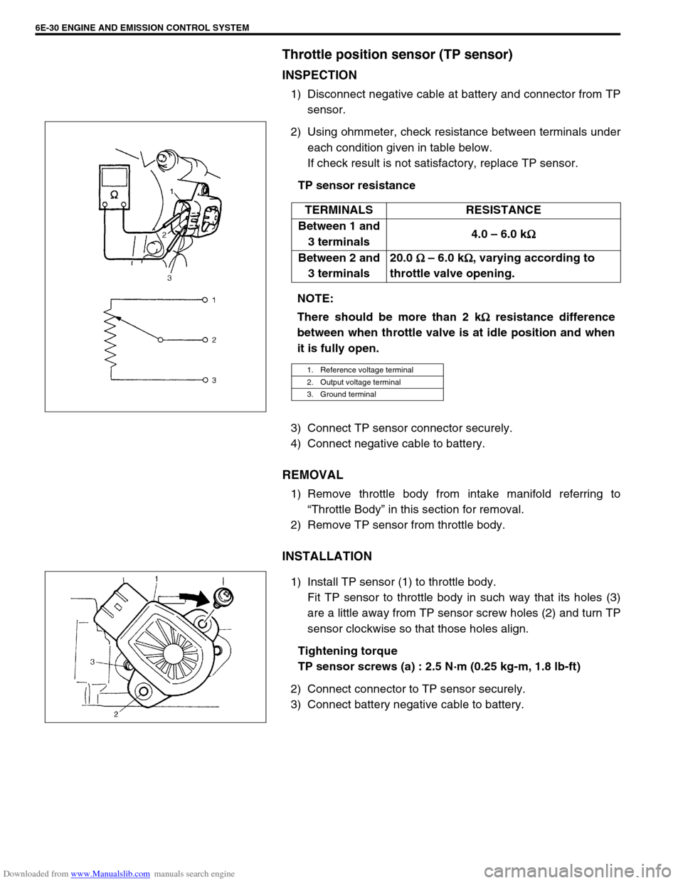
2) Using ohmmeter, check resistance between terminals under
each condition given in table below.
If check result is not satisfactory, replace TP sensor.
TP sensor resistance
3) Connect TP sensor connector securely.
4) Connect negative cable to battery.
REMOVAL
1) Remove throttle body from intake manifold referring to
“Throttle Body” in this section for removal.
2) Remove TP sensor from throttle body.
INSTALLATION
1) Install TP sensor (1) to throttle body.
Fit TP sensor to throttle body in such way that its holes (3)
are a little away from TP sensor screw holes (2) and turn TP
sensor clockwise so that those holes align.
Tightening torque
TP sensor screws (a) : 2.5 N·m (0.25 kg-m, 1.8 lb-ft)
2) Connect connector to TP sensor securely.
3) Connect battery negative cable to battery.TERMINALS RESISTANCE
Between 1 and
3 terminals4.0 – 6.0 k
Ω
ΩΩ Ω
Between 2 and
3 terminals20.0
Ω
ΩΩ Ω – 6.0 k
Ω
ΩΩ Ω, varying according to
throttle valve opening.
NOTE:
There should be more than 2 k
Ω
ΩΩ Ω resistance difference
between when throttle valve is at idle position and when
it is fully open.
1. Reference voltage terminal
2. Output voltage terminal
3. Ground terminal
Page 648 of 687
Downloaded from www.Manualslib.com manuals search engine ENGINE AND EMISSION CONTROL SYSTEM 6E-43
Tightening Torque Specifications
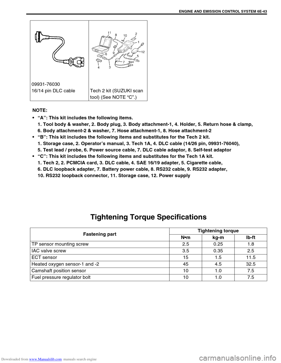
09931-76030
16/14 pin DLC cable Tech 2 kit (SUZUKI scan
tool) (See NOTE “C”.)
NOTE:
“A”: This kit includes the following items.
1. Tool body & washer, 2. Body plug, 3. Body attachment-1, 4. Holder, 5. Return hose & clamp,
6. Body attachment-2 & washer, 7. Hose attachment-1, 8. Hose attachment-2
“B”: This kit includes the following items and substitutes for the Tech 2 kit.
1. Storage case, 2. Operator’s manual, 3. Tech 1A, 4. DLC cable (14/26 pin, 09931-76040),
5. Test lead / probe, 6. Power source cable, 7. DLC cable adaptor, 8. Self-test adaptor
“C”: This kit includes the following items and substitutes for the Tech 1A kit.
1. Tech 2, 2. PCMCIA card, 3. DLC cable, 4. SAE 16/19 adapter, 5. Cigarette cable,
6. DLC loopback adapter, 7. Battery power cable, 8. RS232 cable, 9. RS232 adapter,
10. RS232 loopback connector, 11. Storage case, 12. Power supply
Fastening partTightening torque
Nm kg-m lb-ft
TP sensor mounting screw 2.5 0.25 1.8
IAC valve screw 3.5 0.35 2.5
ECT sensor 15 1.5 11.5
Heated oxygen sensor-1 and -2 45 4.5 32.5
Camshaft position sensor 10 1.0 7.5
Fuel pressure regulator bolt 10 1.0 7.5
Page 658 of 687

Downloaded from www.Manualslib.com manuals search engine IGNITION SYSTEM (ELECTRONIC IGNITION SYSTEM 6F-9
5) Fix ignition timing to initial one as follows.
a) When using SUZUKI scan tool:
Select “MISC” mode on SUZUKI scan tool and fix ignition
timing to initial one.
b) Without using SUZUKI scan tool: (vehicle without immobi-
lizer indicator lamp)
Disconnect scan tool from DLC, and connect D and E ter-
minals of monitor connector (1) or E to body ground by
using service wire so that ignition timing is fixed on initial
one.
6) Using timing light (1), check that ignition timing is within
specification.
Initial ignition timing (test switch terminal grounded or
fixed with SUZUKI scan tool)
5
± 3° BTDC at idle speed
Ignition order
1-3-4-2
7) If ignition timing is out of specification, check the followings:
CKP sensor
CKP sensor plate
TP sensor
Test switch signal circuit
VSS
Timing chain cover installation
8) After checking Initial Ignition Timing, release ignition timing
fixation by using SUZUKI scan tool or disconnect service
wire from monitor connector.
9) With engine idling (test switch terminal ungrounded, throttle
opening at closed position and car stopped), check that igni-
tion timing is about 7°–17° BTDC. (Constant variation within
a few degrees from 7°–17° indicates no abnormality but
proves operation of electronic timing control system.) Also,
check that increasing engine speed advances ignition timing.
If above check results are not satisfactory, check CKP sen-
sor, test switch terminal circuit and ECM.
Page 663 of 687
Downloaded from www.Manualslib.com manuals search engine 6G-4 CRANKING SYSTEM
Performance Test
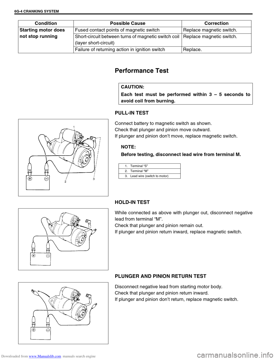
PULL-IN TEST
Connect battery to magnetic switch as shown.
Check that plunger and pinion move outward.
If plunger and pinion don’t move, replace magnetic switch.
HOLD-IN TEST
While connected as above with plunger out, disconnect negative
lead from terminal “M”.
Check that plunger and pinion remain out.
If plunger and pinion return inward, replace magnetic switch.
PLUNGER AND PINION RETURN TEST
Disconnect negative lead from starting motor body.
Check that plunger and pinion return inward.
If plunger and pinion don’t return, replace magnetic switch. Starting motor does
not stop runningFused contact points of magnetic switch Replace magnetic switch.
Short-circuit between turns of magnetic switch coil
(layer short-circuit)Replace magnetic switch.
Failure of returning action in ignition switch Replace.
CAUTION:
Each test must be performed within 3 – 5 seconds to
avoid coil from burning.
NOTE:
Before testing, disconnect lead wire from terminal M.
1. Terminal “S”
2. Terminal “M”
3. Lead wire (switch to motor)
Condition Possible Cause Correction
Page 678 of 687
Downloaded from www.Manualslib.com manuals search engine CHARGING SYSTEM 6H-11
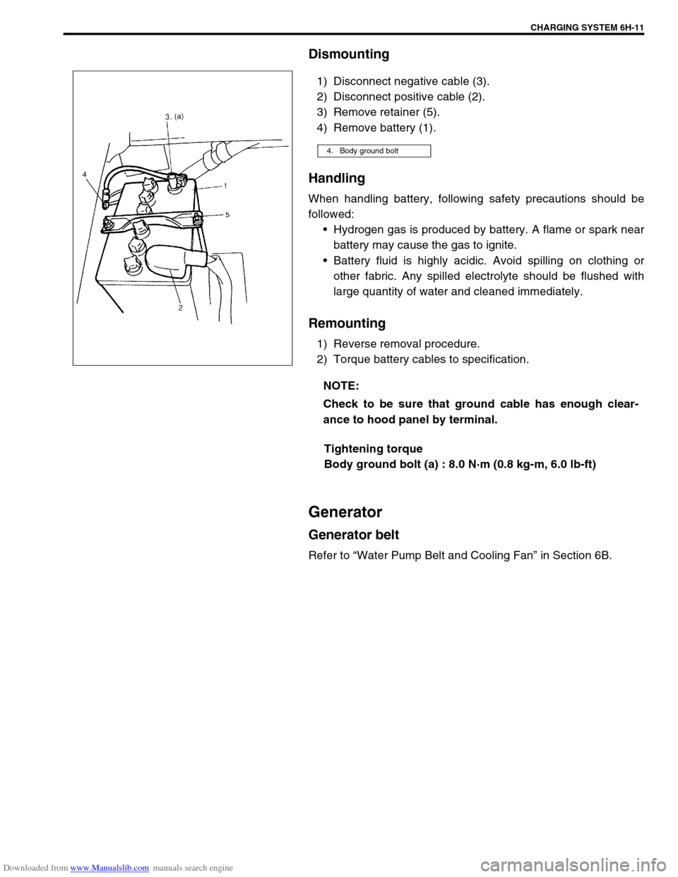
Dismounting
1) Disconnect negative cable (3).
2) Disconnect positive cable (2).
3) Remove retainer (5).
4) Remove battery (1).
Handling
When handling battery, following safety precautions should be
followed:
Hydrogen gas is produced by battery. A flame or spark near
battery may cause the gas to ignite.
Battery fluid is highly acidic. Avoid spilling on clothing or
other fabric. Any spilled electrolyte should be flushed with
large quantity of water and cleaned immediately.
Remounting
1) Reverse removal procedure.
2) Torque battery cables to specification.
Tightening torque
Body ground bolt (a) : 8.0 N·m (0.8 kg-m, 6.0 lb-ft)
Generator
Generator belt
Refer to “Water Pump Belt and Cooling Fan” in Section 6B.
4. Body ground bolt
NOTE:
Check to be sure that ground cable has enough clear-
ance to hood panel by terminal.
Page 684 of 687

Downloaded from www.Manualslib.com manuals search engine CHARGING SYSTEM 6H-17
Specifications
Battery
55B24R TYPE
38B20R TYPE
Generator
Tightening Torque Specification
Rated capacity 36 AH/5HR, 12 Volts
Electrolyte 3.1 L (6.55/5.46 US/lmp pt)
Electrolyte S.G. 1.28 when fully charged at 20 °C (68 °F)
Rated capacity 28 AH/5HR, 12 Volts
Electrolyte 2.1 L (4.44/3.70 US/lmp pt)
Electrolyte S.G. 1.28 when fully charged at 20 °C (68 °F)
Type 70 A type
Rated voltage 12 V
Nominal output 70 A
Permissible max. speed 18,000 r/min.
No-load speed 1,300 r/min (rpm)
Setting voltage 14.4 to 15.0 V
Permissible ambient temperature–30 to 90 °C (–22 to 194 °F)
Polarity Negative ground
Rotation Clockwise viewed from pulley side
Fastening partTightening torque
Nm kg-m lb-ft
Body ground bolt 8 0.8 6.0
Generator mounting bolts 23 2.3 16.5
“B” terminal inner nut 4.2 0.42 3.0
“B” terminal outer nut 8 0.8 6.0
Pulley nut 118 11.8 85.5
Rear end frame nuts
4.50.453.5
Rear end cover nuts
Rectifier “B” bolt 3.9 0.39 3.0
Stator stud bolts 8.8 0.88 6.5
Drive end bearing plate screws 2.6 0.26 2.0
Rectifier screws
2.00.201.5
Regulator and brush holder screws
Terminal plate bolt 3.8 0.38 3.0
Page 686 of 687
Downloaded from www.Manualslib.com manuals search engine EXHAUST SYSTEM 6K-1
6F1
6F2
6G
6H
7D
7E
7F
7D
7E
7F
8A
8B
8C
8D
8E
9
7A1
6K
7C1
SECTION 6K
EXHAUST SYSTEM
CONTENTS
General Description ........................................6K-1
Maintenance ....................................................6K-1On-Vehicle Service ......................................... 6K-2
Exhaust Manifold .......................................... 6K-2
Exhaust Pipe ................................................. 6K-2
General Description
The exhaust system of this vehicle consists of the exhaust manifold, exhaust center pipe, muffler, seals, etc.
The catalytic converter is an emission control device added to the exhaust system to lower the level of Hydro-
carbon (HC), Carbon Monoxide (CO) and Oxides of Nitrogen (NOx) pollutants in the exhaust gas. The catalyst
in the catalytic converter is of “Three way” type.
Maintenance
At every interval of periodic maintenance service, and when vehicle is raised for other service, check exhaust
system as follows:
Check rubber mountings for damage, deterioration and out of position.
Check exhaust system for leakage, loose connection, dent and damage.
If bolts or nuts are loosened, tighten them to specified torque. Refer to “Components” in this section.
Check nearby body areas for damaged, missing, or mispositioned part, open seam, hole, loose connection
or any other defect which could permit exhaust fumes to seep into vehicle.
Make sure that exhaust system components have enough clearance from underbody to avoid overheating
and possible damage to passenger compartment carpet.
Any defect should be fixed at once. NOTE:
Whether following parts are used in the particular vehicle or not depends on specification. Be sure to
bear this in mind when performing service work.
Three-Way Catalytic Converter (TWC)
CAUTION:
Be sure to use UNLEADED FUEL for the catalytic converter equipped vehicle. Use of LEADED FUEL
will affect performance of the catalytic converter adversely to a great extent.
WARNING:
To avoid danger of being burned, do not touch exhaust system when system is hot.
Any service on exhaust system should be performed when system is cool.