torque SUZUKI JIMNY 2005 3.G Service Workshop Manual
[x] Cancel search | Manufacturer: SUZUKI, Model Year: 2005, Model line: JIMNY, Model: SUZUKI JIMNY 2005 3.GPages: 687, PDF Size: 13.38 MB
Page 589 of 687
Downloaded from www.Manualslib.com manuals search engine 6B-12 ENGINE COOLING
INSPECTION
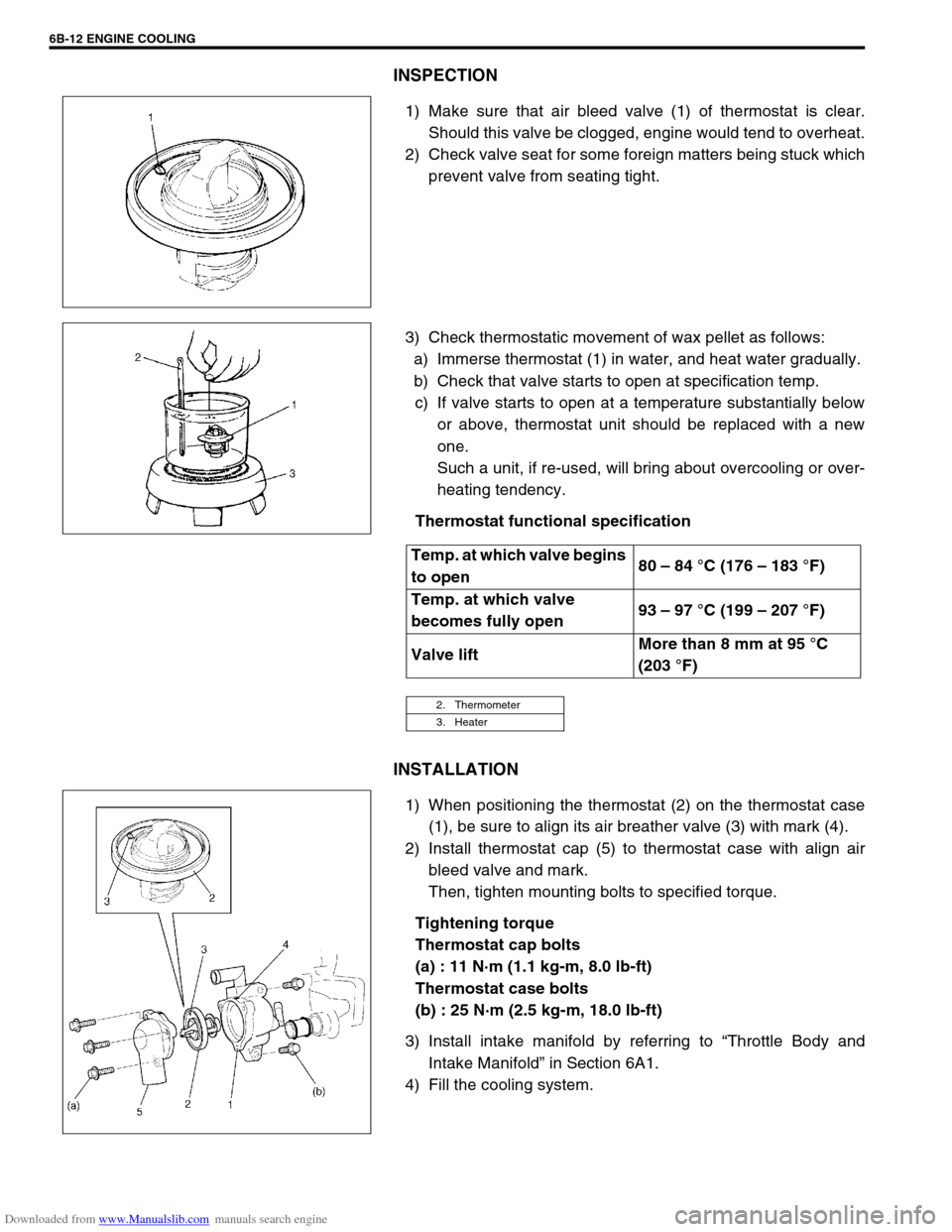
1) Make sure that air bleed valve (1) of thermostat is clear.
Should this valve be clogged, engine would tend to overheat.
2) Check valve seat for some foreign matters being stuck which
prevent valve from seating tight.
3) Check thermostatic movement of wax pellet as follows:
a) Immerse thermostat (1) in water, and heat water gradually.
b) Check that valve starts to open at specification temp.
c) If valve starts to open at a temperature substantially below
or above, thermostat unit should be replaced with a new
one.
Such a unit, if re-used, will bring about overcooling or over-
heating tendency.
Thermostat functional specification
INSTALLATION
1) When positioning the thermostat (2) on the thermostat case
(1), be sure to align its air breather valve (3) with mark (4).
2) Install thermostat cap (5) to thermostat case with align air
bleed valve and mark.
Then, tighten mounting bolts to specified torque.
Tightening torque
Thermostat cap bolts
(a) : 11 N·m (1.1 kg-m, 8.0 lb-ft)
Thermostat case bolts
(b) : 25 N·m (2.5 kg-m, 18.0 lb-ft)
3) Install intake manifold by referring to “Throttle Body and
Intake Manifold” in Section 6A1.
4) Fill the cooling system.
Temp. at which valve begins
to open80 – 84 °C (176 – 183 °F)
Temp. at which valve
becomes fully open93 – 97 °C (199 – 207 °F)
Valve liftMore than 8 mm at 95 °C
(203 °F)
2. Thermometer
3. Heater
Page 592 of 687

Downloaded from www.Manualslib.com manuals search engine ENGINE COOLING 6B-15
Water Pump
COMPONENTS
REMOVAL
1) Drain cooling system.
Refer to Step 6) of “Cooling System Flush and Refill” in this
section.
2) Remove the radiator shroud.
3) Remove radiator referring to “Radiator” in this section.
4) Loosen water pump drive belt tension.
Then remove water pump pulley (2) with fan clutch (3) and
pump drive belt.
5) Remove water pump assembly (1).
1. Water pump 4. Radiator cooling fan 7. Radiator cooling fan mounting bolt
2. Water pump pulley 5. Water pump mounting bolts Tightening Torque
3. Radiator cooling fan clutch 6. Water pump pulley and fan clutch mounting nuts
1. Drain plug
Page 593 of 687
Downloaded from www.Manualslib.com manuals search engine 6B-16 ENGINE COOLING
INSPECTION
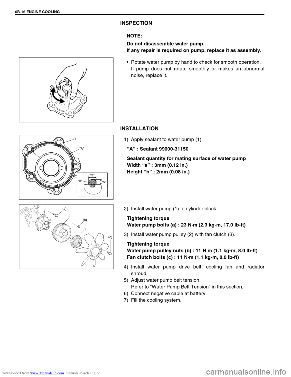
Rotate water pump by hand to check for smooth operation.
If pump does not rotate smoothly or makes an abnormal
noise, replace it.
INSTALLATION
1) Apply sealant to water pump (1).
“A” : Sealant 99000-31150
Sealant quantity for mating surface of water pump
Width “a” : 3mm (0.12 in.)
Height “b” : 2mm (0.08 in.)
2) Install water pump (1) to cylinder block.
Tightening torque
Water pump bolts (a) : 23 N·m (2.3 kg-m, 17.0 lb-ft)
3) Install water pump pulley (2) with fan clutch (3).
Tightening torque
Water pump pulley nuts (b) : 11 N·m (1.1 kg-m, 8.0 lb-ft)
Fan clutch bolts (c) : 11 N·m (1.1 kg-m, 8.0 lb-ft)
4) Install water pump drive belt, cooling fan and radiator
shroud.
5) Adjust water pump belt tension.
Refer to “Water Pump Belt Tension” in this section.
6) Connect negative cable at battery.
7) Fill the cooling system.NOTE:
Do not disassemble water pump.
If any repair is required on pump, replace it as assembly.
Page 594 of 687

Downloaded from www.Manualslib.com manuals search engine ENGINE COOLING 6B-17
Required Service Material
Tightening Torque Specification
MaterialRecommended SUZUKI product
(Part Number)Use
Ethylene glycol base
coolant (Anti-freeze /
Anti-corrosion coolant)–Additive to engine cooling system for improving
cooling efficiency and for protection against
rusting.
SealantSUZUKI BOND NO.1207C
(99000 – 31150)To apply to water pump mating surface.
Fastening partTightening torque
Nm kg-m lb-ft
Water pump bolt 23 2.3 17.0
Thermostat cap bolt 11 1.1 8.0
Thermostat case bolt 25 2.5 18.0
Fun clutch bolt 11 1.1 8.0
Page 596 of 687
Downloaded from www.Manualslib.com manuals search engine ENGINE FUEL 6C-1
6F1
7A
7A1
7A
7A
7A1
7B1
7C1
7D
7E
7F
8A
8B
8C
6G
6C
6K
9
10
10A
10B
SECTION 6C
ENGINE FUEL
CONTENTS
General Description ....................................... 6C-2
Fuel System ................................................. 6C-2
Fuel Tank ..................................................... 6C-2
Fuel Pump Assembly ................................... 6C-3
Fuel Filler Cap .............................................. 6C-3
On-Vehicle Service......................................... 6C-4Fuel Lines .................................................... 6C-4
Fuel Filler Cap.............................................. 6C-4
Fuel Tank ..................................................... 6C-4
Fuel Pump Assembly ................................... 6C-7
Tightening Torque Specification ................ 6C-10
Special Tool .................................................. 6C-10
CAUTION:
For vehicles with a catalytic converter, be sure to use unleaded fuel only. Use of leaded and/or low
lead fuel can result in engine damage and reduce the effectiveness of the emission control system.
Page 597 of 687
Downloaded from www.Manualslib.com manuals search engine 6C-2 ENGINE FUEL
General Description
Fuel System
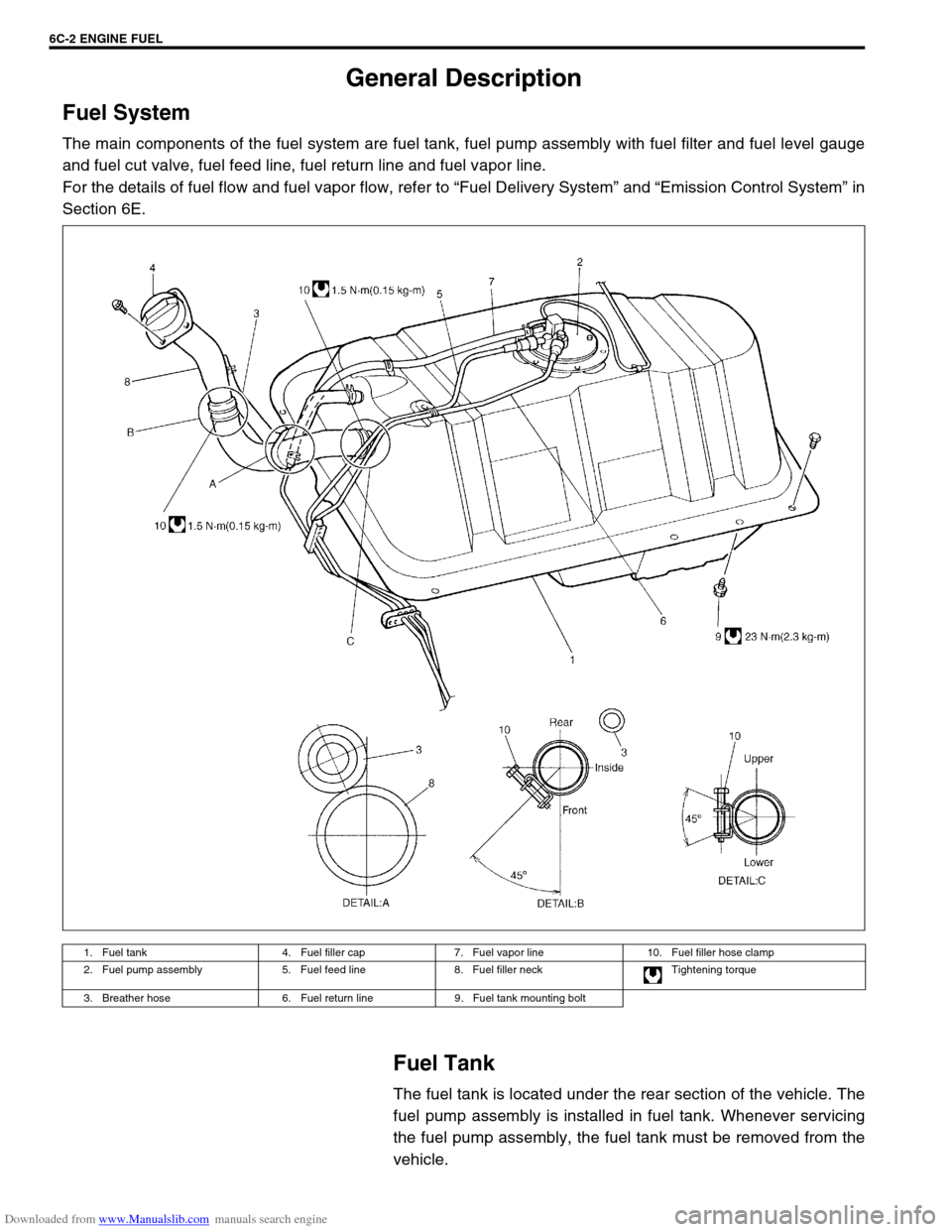
The main components of the fuel system are fuel tank, fuel pump assembly with fuel filter and fuel level gauge
and fuel cut valve, fuel feed line, fuel return line and fuel vapor line.
For the details of fuel flow and fuel vapor flow, refer to “Fuel Delivery System” and “Emission Control System” in
Section 6E.
Fuel Tank
The fuel tank is located under the rear section of the vehicle. The
fuel pump assembly is installed in fuel tank. Whenever servicing
the fuel pump assembly, the fuel tank must be removed from the
vehicle.
1. Fuel tank 4. Fuel filler cap 7. Fuel vapor line 10. Fuel filler hose clamp
2. Fuel pump assembly 5. Fuel feed line 8. Fuel filler neck Tightening torque
3. Breather hose 6. Fuel return line 9. Fuel tank mounting bolt
Page 604 of 687
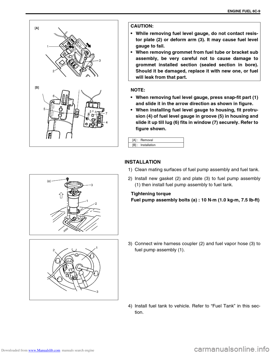
Downloaded from www.Manualslib.com manuals search engine ENGINE FUEL 6C-9
INSTALLATION
1) Clean mating surfaces of fuel pump assembly and fuel tank.
2) Install new gasket (2) and plate (3) to fuel pump assembly
(1) then install fuel pump assembly to fuel tank.
Tightening torque
Fuel pump assembly bolts (a) : 10 N·m (1.0 kg-m, 7.5 lb-ft)
3) Connect wire harness coupler (2) and fuel vapor hose (3) to
fuel pump assembly (1).
4) Install fuel tank to vehicle. Refer to “Fuel Tank” in this sec-
tion. CAUTION:
While removing fuel level gauge, do not contact resis-
tor plate (2) or deform arm (3). It may cause fuel level
gauge to fail.
When removing grommet from fuel tube or bracket sub
assembly, be very careful not to cause damage to
grommet installed section (sealed section in bore).
Should it be damaged, replace it with new one, or fuel
will leak from that part.
NOTE:
When removing fuel level gauge, press snap-fit part (1)
and slide it in the arrow direction as shown in figure.
When installing fuel level gauge to housing, fit protru-
sion (4) of fuel level gauge in groove (5) in housing and
slide it up till lug (6) fits in window (7) securely. Refer to
figure shown.
[A] : Removal
[B] : Installation
Page 605 of 687

Downloaded from www.Manualslib.com manuals search engine 6C-10 ENGINE FUEL
Tightening Torque Specification
Special Tool
Fastening partTightening torque
Nm kg-m lb-ft
Fuel pump assembly bolt 10 1.0 7.5
09919-47020
Quick joint remover
Page 607 of 687

Downloaded from www.Manualslib.com manuals search engine 6E-2 ENGINE AND EMISSION CONTROL SYSTEM
EGR system (If equipped) ...................... 6E-38
Evaporative emission (EVAP) control
system .................................................... 6E-39
PCV system ........................................... 6E-41Special Tools ............................................... 6E-42
Tightening Torque Specifications .............. 6E-43
Page 623 of 687

Downloaded from www.Manualslib.com manuals search engine 6E-18 ENGINE AND EMISSION CONTROL SYSTEM
Air Intake System
Throttle body
ON-VEHICLE INSPECTION
Check that throttle valve lever (1) moves smoothly.
REMOVAL
1) Disconnect negative cable at battery.
2) Drain cooling system.
3) Disconnect accelerator cable (1) from throttle valve lever.
1. Throttle body 4. Gasket 7. TP sensor screws
2. Throttle body gasket 5. Idle air control valve Tightening torque
3. TP sensor 6. IAC valve screws Do not reuse