torque SUZUKI JIMNY 2005 3.G Service Workshop Manual
[x] Cancel search | Manufacturer: SUZUKI, Model Year: 2005, Model line: JIMNY, Model: SUZUKI JIMNY 2005 3.GPages: 687, PDF Size: 13.38 MB
Page 626 of 687
Downloaded from www.Manualslib.com manuals search engine ENGINE AND EMISSION CONTROL SYSTEM 6E-21
Idle air control valve (IAC valve)
REMOVAL
1) Remove throttle body from intake manifold referring to
“Throttle Body” in this section for removal.
2) Remove IAC valve from throttle body.
INSPECTION
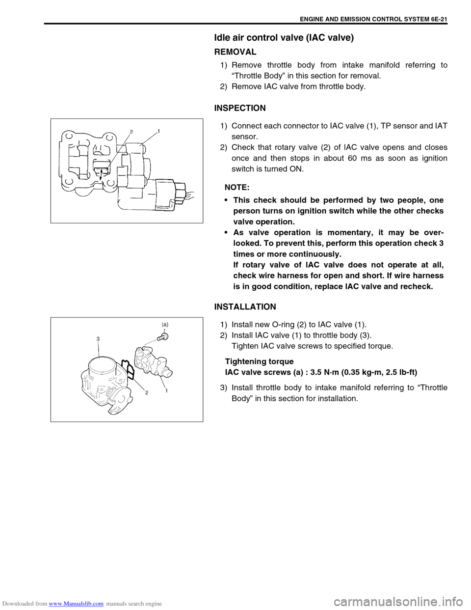
1) Connect each connector to IAC valve (1), TP sensor and IAT
sensor.
2) Check that rotary valve (2) of lAC valve opens and closes
once and then stops in about 60 ms as soon as ignition
switch is turned ON.
INSTALLATION
1) Install new O-ring (2) to IAC valve (1).
2) Install IAC valve (1) to throttle body (3).
Tighten IAC valve screws to specified torque.
Tightening torque
IAC valve screws (a) : 3.5 N·m (0.35 kg-m, 2.5 lb-ft)
3) Install throttle body to intake manifold referring to “Throttle
Body” in this section for installation. NOTE:
This check should be performed by two people, one
person turns on ignition switch while the other checks
valve operation.
As valve operation is momentary, it may be over-
looked. To prevent this, perform this operation check 3
times or more continuously.
If rotary valve of lAC valve does not operate at all,
check wire harness for open and short. If wire harness
is in good condition, replace lAC valve and recheck.
Page 630 of 687
Downloaded from www.Manualslib.com manuals search engine ENGINE AND EMISSION CONTROL SYSTEM 6E-25
INSTALLATION
For installation, reverse removal procedure and note following
precautions.
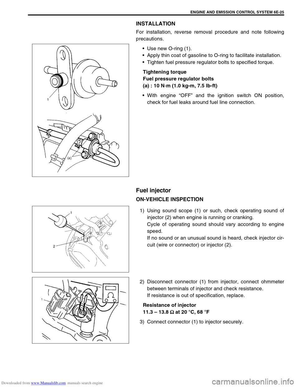
Use new O-ring (1).
Apply thin coat of gasoline to O-ring to facilitate installation.
Tighten fuel pressure regulator bolts to specified torque.
Tightening torque
Fuel pressure regulator bolts
(a) : 10 N·m (1.0 kg-m, 7.5 lb-ft)
With engine “OFF” and the ignition switch ON position,
check for fuel leaks around fuel line connection.
Fuel injector
ON-VEHICLE INSPECTION
1) Using sound scope (1) or such, check operating sound of
injector (2) when engine is running or cranking.
Cycle of operating sound should vary according to engine
speed.
If no sound or an unusual sound is heard, check injector cir-
cuit (wire or connector) or injector (2).
2) Disconnect connector (1) from injector, connect ohmmeter
between terminals of injector and check resistance.
If resistance is out of specification, replace.
Resistance of injector
11.3 – 13.8
Ω
ΩΩ Ω at 20 °C, 68 °F
3) Connect connector (1) to injector securely.
Page 635 of 687
Downloaded from www.Manualslib.com manuals search engine 6E-30 ENGINE AND EMISSION CONTROL SYSTEM
Throttle position sensor (TP sensor)
INSPECTION
1) Disconnect negative cable at battery and connector from TP
sensor.
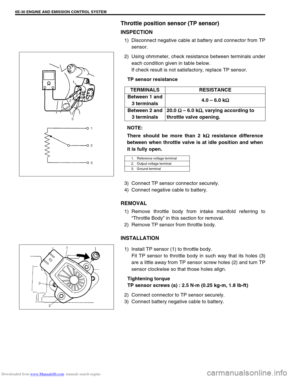
2) Using ohmmeter, check resistance between terminals under
each condition given in table below.
If check result is not satisfactory, replace TP sensor.
TP sensor resistance
3) Connect TP sensor connector securely.
4) Connect negative cable to battery.
REMOVAL
1) Remove throttle body from intake manifold referring to
“Throttle Body” in this section for removal.
2) Remove TP sensor from throttle body.
INSTALLATION
1) Install TP sensor (1) to throttle body.
Fit TP sensor to throttle body in such way that its holes (3)
are a little away from TP sensor screw holes (2) and turn TP
sensor clockwise so that those holes align.
Tightening torque
TP sensor screws (a) : 2.5 N·m (0.25 kg-m, 1.8 lb-ft)
2) Connect connector to TP sensor securely.
3) Connect battery negative cable to battery.TERMINALS RESISTANCE
Between 1 and
3 terminals4.0 – 6.0 k
Ω
ΩΩ Ω
Between 2 and
3 terminals20.0
Ω
ΩΩ Ω – 6.0 k
Ω
ΩΩ Ω, varying according to
throttle valve opening.
NOTE:
There should be more than 2 k
Ω
ΩΩ Ω resistance difference
between when throttle valve is at idle position and when
it is fully open.
1. Reference voltage terminal
2. Output voltage terminal
3. Ground terminal
Page 638 of 687
Downloaded from www.Manualslib.com manuals search engine ENGINE AND EMISSION CONTROL SYSTEM 6E-33
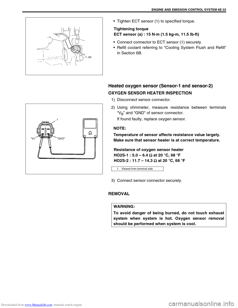
Tighten ECT sensor (1) to specified torque.
Tightening torque
ECT sensor (a) : 15 N·m (1.5 kg-m, 11.5 lb-ft)
Connect connector to ECT sensor (1) securely.
Refill coolant referring to “Cooling System Flush and Refill”
in Section 6B.
Heated oxygen sensor (Sensor-1 and sensor-2)
OXYGEN SENSOR HEATER INSPECTION
1) Disconnect sensor connector.
2) Using ohmmeter, measure resistance between terminals
“V
B” and “GND” of sensor connector.
If found faulty, replace oxygen sensor.
Resistance of oxygen sensor heater
HO2S-1 : 5.0 – 6.4
Ω
ΩΩ Ω at 20 °C, 68 °F
HO2S-2 : 11.7 – 14.3
Ω
ΩΩ Ω at 20 °C, 68 °F
3) Connect sensor connector securely.
REMOVAL
NOTE:
Temperature of sensor affects resistance value largely.
Make sure that sensor heater is at correct temperature.
1. Viewed from terminal side
WARNING:
To avoid danger of being burned, do not touch exhaust
system when system is hot. Oxygen sensor removal
should be performed when system is cool.
Page 639 of 687
Downloaded from www.Manualslib.com manuals search engine 6E-34 ENGINE AND EMISSION CONTROL SYSTEM
1) Disconnect negative cable at battery.
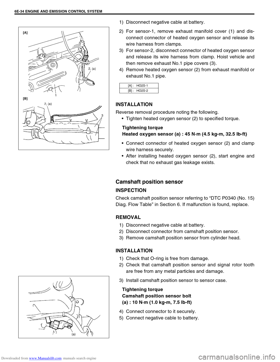
2) For sensor-1, remove exhaust manifold cover (1) and dis-
connect connector of heated oxygen sensor and release its
wire harness from clamps.
3) For sensor-2, disconnect connector of heated oxygen sensor
and release its wire harness from clamp. Hoist vehicle and
then remove exhaust No.1 pipe covers (3).
4) Remove heated oxygen sensor (2) from exhaust manifold or
exhaust No.1 pipe.
INSTALLATION
Reverse removal procedure noting the following.
Tighten heated oxygen sensor (2) to specified torque.
Tightening torque
Heated oxygen sensor (a) : 45 N·m (4.5 kg-m, 32.5 lb-ft)
Connect connector of heated oxygen sensor (2) and clamp
wire harness securely.
After installing heated oxygen sensor (2), start engine and
check that no exhaust gas leakage exists.
Camshaft position sensor
INSPECTION
Check camshaft position sensor referring to “DTC P0340 (No. 15)
Diag. Flow Table” in Section 6. If malfunction is found, replace.
REMOVAL
1) Disconnect negative cable at battery.
2) Disconnect connector from camshaft position sensor.
3) Remove camshaft position sensor from cylinder head.
INSTALLATION
1) Check that O-ring is free from damage.
2) Check that camshaft position sensor and signal rotor tooth
are free from any metal particles and damage.
3) Install camshaft position sensor to sensor case.
Tightening torque
Camshaft position sensor bolt
(a) : 10 N·m (1.0 kg-m, 7.5 lb-ft)
4) Connect connector to it securely.
5) Connect negative cable to battery.
[A] : HO2S-1
[B] : HO2S-2
Page 648 of 687
Downloaded from www.Manualslib.com manuals search engine ENGINE AND EMISSION CONTROL SYSTEM 6E-43
Tightening Torque Specifications
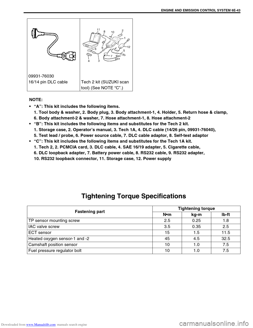
09931-76030
16/14 pin DLC cable Tech 2 kit (SUZUKI scan
tool) (See NOTE “C”.)
NOTE:
“A”: This kit includes the following items.
1. Tool body & washer, 2. Body plug, 3. Body attachment-1, 4. Holder, 5. Return hose & clamp,
6. Body attachment-2 & washer, 7. Hose attachment-1, 8. Hose attachment-2
“B”: This kit includes the following items and substitutes for the Tech 2 kit.
1. Storage case, 2. Operator’s manual, 3. Tech 1A, 4. DLC cable (14/26 pin, 09931-76040),
5. Test lead / probe, 6. Power source cable, 7. DLC cable adaptor, 8. Self-test adaptor
“C”: This kit includes the following items and substitutes for the Tech 1A kit.
1. Tech 2, 2. PCMCIA card, 3. DLC cable, 4. SAE 16/19 adapter, 5. Cigarette cable,
6. DLC loopback adapter, 7. Battery power cable, 8. RS232 cable, 9. RS232 adapter,
10. RS232 loopback connector, 11. Storage case, 12. Power supply
Fastening partTightening torque
Nm kg-m lb-ft
TP sensor mounting screw 2.5 0.25 1.8
IAC valve screw 3.5 0.35 2.5
ECT sensor 15 1.5 11.5
Heated oxygen sensor-1 and -2 45 4.5 32.5
Camshaft position sensor 10 1.0 7.5
Fuel pressure regulator bolt 10 1.0 7.5
Page 650 of 687

Downloaded from www.Manualslib.com manuals search engine IGNITION SYSTEM (ELECTRONIC IGNITION SYSTEM) 6F-1
6G
6F2
6G
6H
7D
7E
7F
7A1
7A1
7D
7E
7F
8A
8B
8C
8D
8E
6K
6F
7A
10
10A
10B
SECTION 6F
IGNITION SYSTEM
(ELECTRONIC IGNITION SYSTEM)
CONTENTS
General Description ........................................ 6F-2
Diagnosis ......................................................... 6F-3
On-Vehicle Service.......................................... 6F-5
Ignition Spark Test ........................................ 6F-5
High-tension Cords ....................................... 6F-5
Spark Plugs ................................................... 6F-6Ignition Coil Assembly (Including Ignitor) ...... 6F-7
Crankshaft Position Sensor (CKP Sensor) ... 6F-8
Ignition Timing............................................... 6F-8
Special Tools ................................................. 6F-10
Tightening Torque Specification ................. 6F-10
WARNING:
For vehicles equipped with Supplemental Restraint (Air Bag) System:
Service on and around the air bag system components or wiring must be performed only by an
authorized SUZUKI dealer. Refer to “Air Bag System Components and Wiring Location View” under
“General Description” in air bag system section in order to confirm whether you are performing ser-
vice on or near the air bag system components or wiring. Please observe all WARNINGS and “Ser-
vice Precautions” under “On-Vehicle Service” in air bag system section before performing service
on or around the air bag system components or wiring. Failure to follow WARNINGS could result in
unintentional activation of the system or could render the system inoperative. Either of these two
conditions may result in severe injury.
Technical service work must be started at least 90 seconds after the ignition switch is turned to the
“LOCK” position and the negative cable is disconnected from the battery. Otherwise, the system
may be activated by reserve energy in the Sensing and Diagnostic Module (SDM).
Page 656 of 687
Downloaded from www.Manualslib.com manuals search engine IGNITION SYSTEM (ELECTRONIC IGNITION SYSTEM 6F-7
4) If any abnormality is found, adjust air gap, clean with spark
plug cleaner or replace them with specified new plugs.
For iridium/platinum spark plugs, replace them with new
plugs.
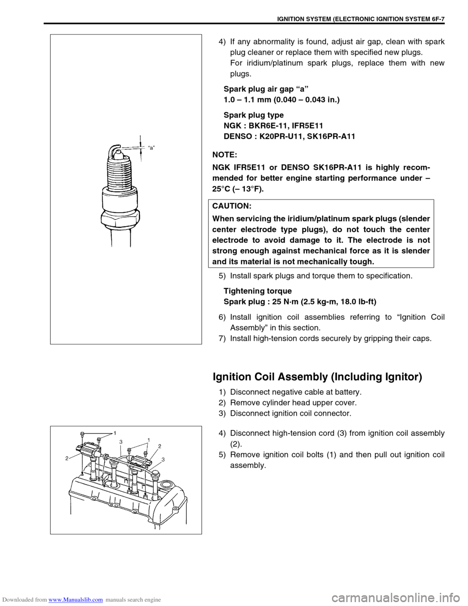
Spark plug air gap “a”
1.0 – 1.1 mm (0.040 – 0.043 in.)
Spark plug type
NGK : BKR6E-11, IFR5E11
DENSO : K20PR-U11, SK16PR-A11
5) Install spark plugs and torque them to specification.
Tightening torque
Spark plug : 25 N·m (2.5 kg-m, 18.0 lb-ft)
6) Install ignition coil assemblies referring to “Ignition Coil
Assembly” in this section.
7) Install high-tension cords securely by gripping their caps.
Ignition Coil Assembly (Including Ignitor)
1) Disconnect negative cable at battery.
2) Remove cylinder head upper cover.
3) Disconnect ignition coil connector.
4) Disconnect high-tension cord (3) from ignition coil assembly
(2).
5) Remove ignition coil bolts (1) and then pull out ignition coil
assembly. NOTE:
NGK IFR5E11 or DENSO SK16PR-A11 is highly recom-
mended for better engine starting performance under –
25°C (– 13°F).
CAUTION:
When servicing the iridium/platinum spark plugs (slender
center electrode type plugs), do not touch the center
electrode to avoid damage to it. The electrode is not
strong enough against mechanical force as it is slender
and its material is not mechanically tough.
Page 659 of 687
Downloaded from www.Manualslib.com manuals search engine 6F-10 IGNITION SYSTEM (ELECTRONIC IGNITION SYSTEM)
Special Tools
Tightening Torque Specification
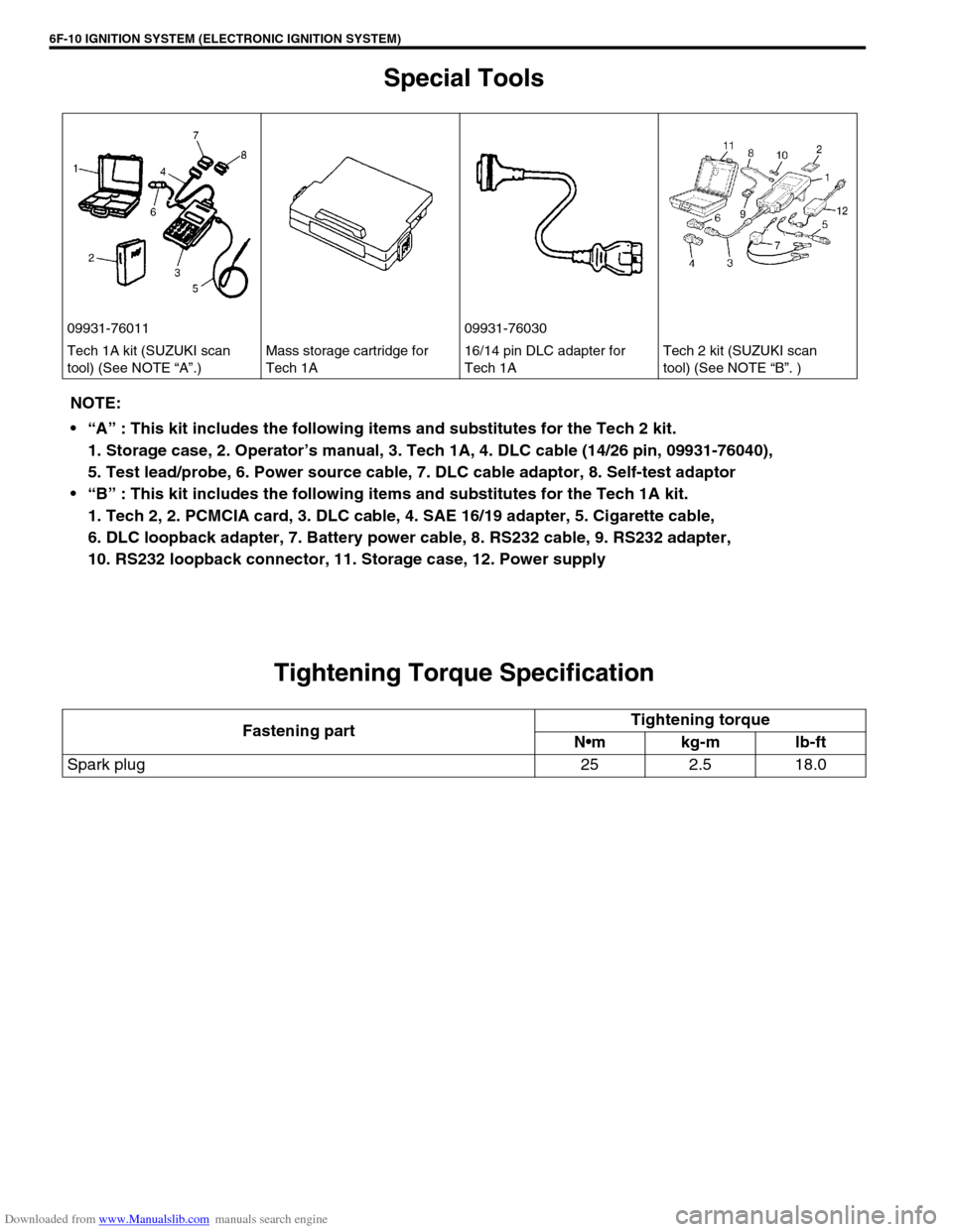
09931-76011 09931-76030
Tech 1A kit (SUZUKI scan
tool) (See NOTE “A”.)Mass storage cartridge for
Tech 1A16/14 pin DLC adapter for
Tech 1ATech 2 kit (SUZUKI scan
tool) (See NOTE “B”. )
NOTE:
“A” : This kit includes the following items and substitutes for the Tech 2 kit.
1. Storage case, 2. Operator’s manual, 3. Tech 1A, 4. DLC cable (14/26 pin, 09931-76040),
5. Test lead/probe, 6. Power source cable, 7. DLC cable adaptor, 8. Self-test adaptor
“B” : This kit includes the following items and substitutes for the Tech 1A kit.
1. Tech 2, 2. PCMCIA card, 3. DLC cable, 4. SAE 16/19 adapter, 5. Cigarette cable,
6. DLC loopback adapter, 7. Battery power cable, 8. RS232 cable, 9. RS232 adapter,
10. RS232 loopback connector, 11. Storage case, 12. Power supply
Fastening partTightening torque
Nm kg-m lb-ft
Spark plug 25 2.5 18.0
Page 662 of 687

Downloaded from www.Manualslib.com manuals search engine CRANKING SYSTEM 6G-3
Condition Possible Cause Correction
Motor not running
(No operating sound of
magnetic switch)Shift lever switch is not in P or N, or not adjusted
(A/T)Shift in P or N, or adjust switch.
Battery run down Recharge battery.
Battery voltage too low due to battery deteriora-
tionReplace battery.
Poor contact in battery terminal connection Retighten or replace.
Loose grounding cable connection Retighten.
Fuse set loose or blown off Tighten or replace.
Poor contacting action of ignition switch and mag-
netic switchReplace.
Lead wire coupler loose in place Retighten.
Open-circuit between ignition switch and magnetic
switchRepair.
Open-circuit in pull-in coil Replace magnetic switch.
Brushes are seating poorly or worn down Repair or replace.
Poor sliding of plunger and/or pinion Repair.
Motor not running
(Operating sound of
magnetic switch
heard)Battery run down Recharge battery.
Battery voltage too low due to battery deteriora-
tionReplace battery.
Loose battery cable connections Retighten.
Burnt main contact point, or poor contacting action
of magnetic switchReplace magnetic switch.
Brushes are seating poorly or worn down Repair or replace.
Weakened brush spring Replace.
Burnt commutator Replace armature.
Layer short-circuit of armature Replace.
Crankshaft rotation obstructed Repair.
Starting motor running
but too slow (small
torque) (If battery and
wiring are satisfac-
tory, inspect starting
motor)Insufficient contact of magnetic switch main con-
tactsReplace magnetic switch.
Layer short-circuit of armature Replace.
Disconnected, burnt or worn commutator Repair commutator or replace
armature.
Worn brushes Replace brush.
Weakened brush springs Replace spring.
Burnt or abnormally worn end bush Replace bush.
Starting motor run-
ning, but not cranking
engineWorn pinion tip Replace over-running clutch.
Poor sliding of over-running clutch Repair.
Over-running clutch slipping Replace over-running clutch.
Worn teeth of ring gear Replace flywheel (M/T) or drive
plate (A/T).
Noise
Abnormally worn bush Replace bush.
Worn pinion or worn teeth of ring gear Replace pinion or flywheel
(M/T) or drive plate (A/T).
Poor sliding of pinion (failure in return movement) Repair or replace.
Worn internal or planetary gear teeth Replace.
Lack of oil in each part Lubricate.