body SUZUKI JIMNY 2005 3.G Service Owner's Manual
[x] Cancel search | Manufacturer: SUZUKI, Model Year: 2005, Model line: JIMNY, Model: SUZUKI JIMNY 2005 3.GPages: 687, PDF Size: 13.38 MB
Page 104 of 687
Downloaded from www.Manualslib.com manuals search engine AIR CONDITIONING (OPTIONAL) 1B-43
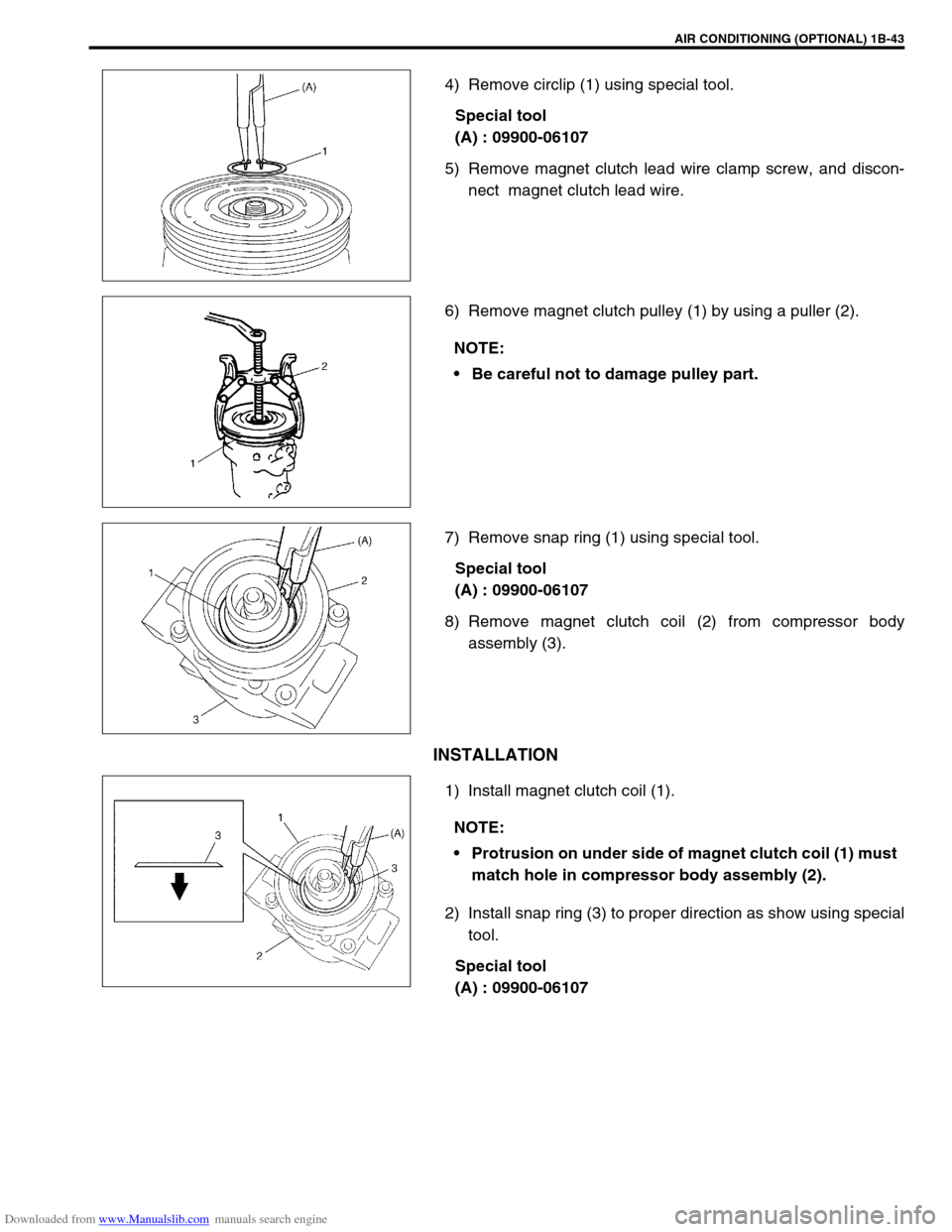
4) Remove circlip (1) using special tool.
Special tool
(A) : 09900-06107
5) Remove magnet clutch lead wire clamp screw, and discon-
nect magnet clutch lead wire.
6) Remove magnet clutch pulley (1) by using a puller (2).
7) Remove snap ring (1) using special tool.
Special tool
(A) : 09900-06107
8) Remove magnet clutch coil (2) from compressor body
assembly (3).
INSTALLATION
1) Install magnet clutch coil (1).
2) Install snap ring (3) to proper direction as show using special
tool.
Special tool
(A) : 09900-06107
NOTE:
Be careful not to damage pulley part.
NOTE:
Protrusion on under side of magnet clutch coil (1) must
match hole in compressor body assembly (2).
Page 106 of 687

Downloaded from www.Manualslib.com manuals search engine AIR CONDITIONING (OPTIONAL) 1B-45
Lip Type Seal
REMOVAL
1) Remove magnet clutch referring to “Magnet Clutch” in this
section.
2) Remove front head mounting bolts (10 pcs).
3) Remove front head (1) by pushing compressor shaft (2).
4) Remove O-ring (5).
5) Remove lip type seal from front head (1) using bearing
remover (2).
INSTALLATION
1) Press-fit lip type seal (1) into front head (2) using special
tool.
Special tool
(A) : 09991-06050
1. Front head
NOTE:
Be careful not to remove cylinder (3) from compressor
body assembly (4).
CAUTION:
Do not reuse lip seal (1) once removed from compressor.
Page 107 of 687
Downloaded from www.Manualslib.com manuals search engine 1B-46 AIR CONDITIONING (OPTIONAL)
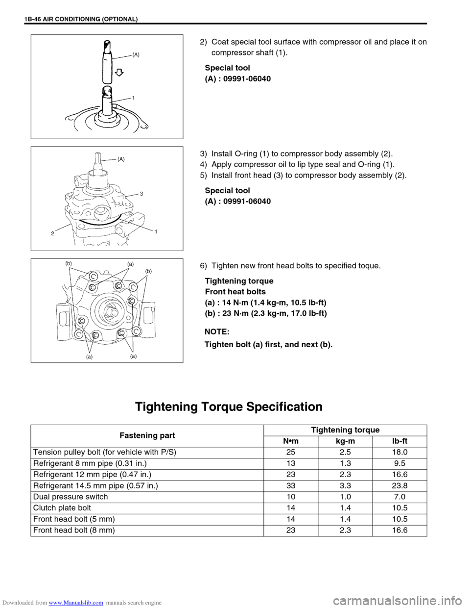
2) Coat special tool surface with compressor oil and place it on
compressor shaft (1).
Special tool
(A) : 09991-06040
3) Install O-ring (1) to compressor body assembly (2).
4) Apply compressor oil to lip type seal and O-ring (1).
5) Install front head (3) to compressor body assembly (2).
Special tool
(A) : 09991-06040
6) Tighten new front head bolts to specified toque.
Tightening torque
Front heat bolts
(a) : 14 N·m (1.4 kg-m, 10.5 lb-ft)
(b) : 23 N·m (2.3 kg-m, 17.0 lb-ft)
Tightening Torque Specification
NOTE:
Tighten bolt (a) first, and next (b).
Fastening partTightening torque
Nm kg-m lb-ft
Tension pulley bolt (for vehicle with P/S) 25 2.5 18.0
Refrigerant 8 mm pipe (0.31 in.) 13 1.3 9.5
Refrigerant 12 mm pipe (0.47 in.) 23 2.3 16.6
Refrigerant 14.5 mm pipe (0.57 in.) 33 3.3 23.8
Dual pressure switch 10 1.0 7.0
Clutch plate bolt 14 1.4 10.5
Front head bolt (5 mm) 14 1.4 10.5
Front head bolt (8 mm) 23 2.3 16.6
Page 113 of 687

Downloaded from www.Manualslib.com manuals search engine 3-4 STEERING, SUSPENSION, WHEELS AND TIRES
Abnormal Noise,
Front EndWorn, sticky or loose tie rod ends, drug rod ball
joints, king pin bearings or axle shaft jointsReplace tie rod end, king pin bear-
ing or axle shaft joint.
Damaged shock absorbers or mountings Replace or repair.
Worn leading arm bushings Replace.
Worn stabilizer bar bushings Replace.
Worn Iateral rod bushings Replace.
Loose stabilizer bar Tighten bolts or replace bushes.
Loose wheel nuts Tighten wheel nuts.
Loose suspension bolts or nuts Tighten suspension bolts or nuts.
Broken or otherwise damaged wheel bearings Replace wheel bearing.
Broken suspension springs Replace spring.
Wander or Poor
Steering StabilityMismatched or uneven tires Replace tire or inflate tires to
proper pressure.
Loose king pin bearings and tie rod ends Replace king pin bearing or tie rod
end.
Faulty shock absorbers or mounting Replace absorber or repair mount-
ing.
Loose stabilizer bar Tighten or replace stabilizer bar or
bushes.
Broken or sagging springs Replace spring.
Steering gear box not properly adjusted Check or adjust steering gear box
torque.
Front wheel alignment Check and adjust front wheel align-
ment.
Erratic Steering when
BrakingWorn wheel bearings Replace wheel bearing.
Broken or sagging springs Replace spring.
Leaking wheel cylinder or caliper Repair or replace wheel cylinder or
caliper.
Warped discs Replace brake disc.
Badly worn brake linings Replace brake shoe lining.
Drum is out of round in some brakes Replace brake drum.
Wheel tires are inflated unequally Inflate tires to proper pressure.
Defective wheel cylinders Replace or repair wheel cylinder.
Disturbed front wheel alignment Check front wheel alignment
Ride Too Soft
Faulty shock absorber Replace shock absorber.
Suspension bottoms
Overloaded Check loading.
Faulty shocks absorber Replace shock absorber.
Incorrect, broken or sagging springs Replace spring.
Body Leans or Sways
in CornersLoose stabilizer bar Tighten stabilizer bar bolts or
replace bushes.
Faulty shocks absorbers or mounting Replace shock absorber or tighten
mounting.
Broken or sagging springs Replace spring.
Overloaded Check loading.
Cupped Tires
Worn wheel bearings Replace wheel bearing.
Excessive tire or wheel run-out Replace tire or wheel disc.
Tire out of balance Adjust tire balance. Condition Possible Cause Correction
Page 119 of 687
Downloaded from www.Manualslib.com manuals search engine 3A-2 FRONT WHEEL ALIGNMENT
General Description
Front alignment refers to the angular relationship between the
front wheels, the front suspension attaching parts and the ground.
Generally, the only adjustment required for front wheel alignment
is toe setting.
Camber and caster can’t be adjusted. Therefore, should camber
or caster be out of specification due to the damage caused by
hazardous road conditions or collision, whether the damage is in
body or in suspension should be determined. If the body is dam-
aged, it should be repaired and if suspension is damaged, it
should be replaced.
Toe Setting
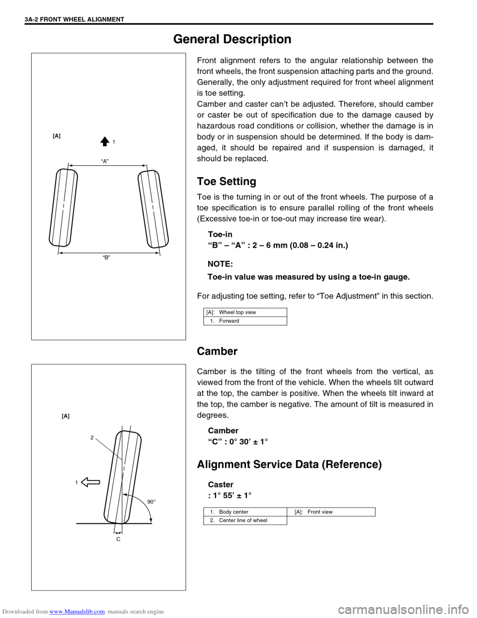
Toe is the turning in or out of the front wheels. The purpose of a
toe specification is to ensure parallel rolling of the front wheels
(Excessive toe-in or toe-out may increase tire wear).
Toe-in
“B” – “A” : 2 – 6 mm (0.08 – 0.24 in.)
For adjusting toe setting, refer to “Toe Adjustment” in this section.
Camber
Camber is the tilting of the front wheels from the vertical, as
viewed from the front of the vehicle. When the wheels tilt outward
at the top, the camber is positive. When the wheels tilt inward at
the top, the camber is negative. The amount of tilt is measured in
degrees.
Camber
“C” : 0° 30’ ± 1°
Alignment Service Data (Reference)
Caster
: 1° 55’ ± 1° NOTE:
Toe-in value was measured by using a toe-in gauge.
[A]: Wheel top view
1. Forward
“A”
“B”1 [A]
1. Body center [A]: Front view
2. Center line of wheel
2
1
90
o
C [A]
Page 121 of 687
Downloaded from www.Manualslib.com manuals search engine 3A-4 FRONT WHEEL ALIGNMENT
Camber And Caster Check And Adjustment
Should camber or caster be found out of specifications upon
inspection, locate its cause first. If it is in damaged, loose, bent,
dented or worn suspension parts and axle housing, they should
be replaced. If it is in vehicle body, repair it so as to attain specifi-
cations.
Steering Angle Check And Adjustment
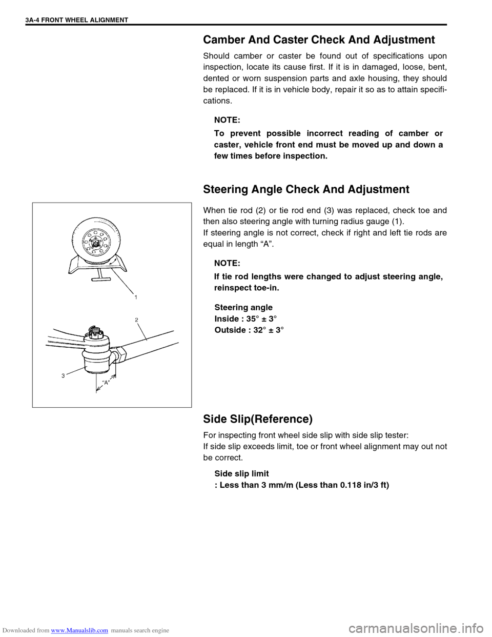
When tie rod (2) or tie rod end (3) was replaced, check toe and
then also steering angle with turning radius gauge (1).
If steering angle is not correct, check if right and left tie rods are
equal in length “A”.
Steering angle
Inside : 35° ± 3°
Outside : 32° ± 3°
Side Slip(Reference)
For inspecting front wheel side slip with side slip tester:
If side slip exceeds limit, toe or front wheel alignment may out not
be correct.
Side slip limit
: Less than 3 mm/m (Less than 0.118 in/3 ft) NOTE:
To prevent possible incorrect reading of camber or
caster, vehicle front end must be moved up and down a
few times before inspection.
NOTE:
If tie rod lengths were changed to adjust steering angle,
reinspect toe-in.
Page 144 of 687
Downloaded from www.Manualslib.com manuals search engine POWER STEERING (P/S) SYSTEM (If equipped) 3B1-13
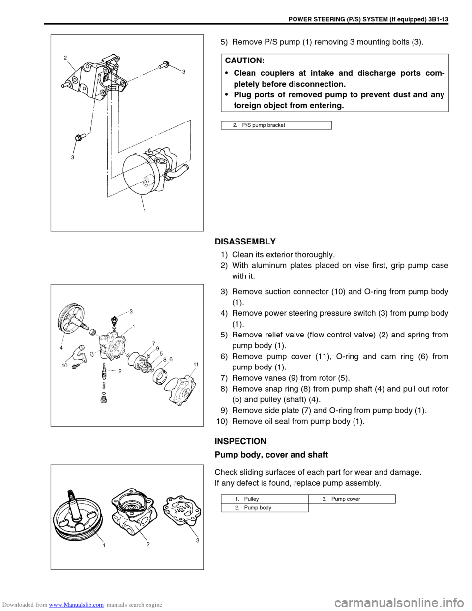
5) Remove P/S pump (1) removing 3 mounting bolts (3).
DISASSEMBLY
1) Clean its exterior thoroughly.
2) With aluminum plates placed on vise first, grip pump case
with it.
3) Remove suction connector (10) and O-ring from pump body
(1).
4) Remove power steering pressure switch (3) from pump body
(1).
5) Remove relief valve (flow control valve) (2) and spring from
pump body (1).
6) Remove pump cover (11), O-ring and cam ring (6) from
pump body (1).
7) Remove vanes (9) from rotor (5).
8) Remove snap ring (8) from pump shaft (4) and pull out rotor
(5) and pulley (shaft) (4).
9) Remove side plate (7) and O-ring from pump body (1).
10) Remove oil seal from pump body (1).
INSPECTION
Pump body, cover and shaft
Check sliding surfaces of each part for wear and damage.
If any defect is found, replace pump assembly.CAUTION:
Clean couplers at intake and discharge ports com-
pletely before disconnection.
Plug ports of removed pump to prevent dust and any
foreign object from entering.
2. P/S pump bracket
1. Pulley 3. Pump cover
2. Pump body
Page 146 of 687
Downloaded from www.Manualslib.com manuals search engine POWER STEERING (P/S) SYSTEM (If equipped) 3B1-15
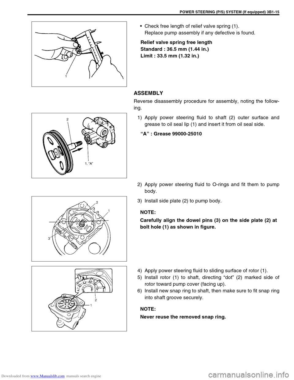
Check free length of relief valve spring (1).
Replace pump assembly if any defective is found.
Relief valve spring free length
Standard : 36.5 mm (1.44 in.)
Limit : 33.5 mm (1.32 in.)
ASSEMBLY
Reverse disassembly procedure for assembly, noting the follow-
ing.
1) Apply power steering fluid to shaft (2) outer surface and
grease to oil seal lip (1) and insert it from oil seal side.
“A” : Grease 99000-25010
2) Apply power steering fluid to O-rings and fit them to pump
body.
3) Install side plate (2) to pump body.
4) Apply power steering fluid to sliding surface of rotor (1).
5) Install rotor (1) to shaft, directing “dot” (2) marked side of
rotor toward pump cover (facing up).
6) Install new snap ring to shaft, then make sure to fit snap ring
into shaft groove securely.
NOTE:
Carefully align the dowel pins (3) on the side plate (2) at
bolt hole (1) as shown in figure.
NOTE:
Never reuse the removed snap ring.
Page 147 of 687
Downloaded from www.Manualslib.com manuals search engine 3B1-16 POWER STEERING (P/S) SYSTEM (If equipped)
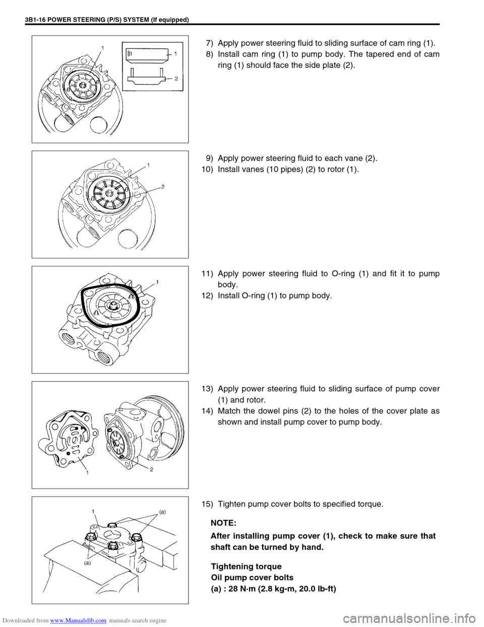
7) Apply power steering fluid to sliding surface of cam ring (1).
8) Install cam ring (1) to pump body. The tapered end of cam
ring (1) should face the side plate (2).
9) Apply power steering fluid to each vane (2).
10) Install vanes (10 pipes) (2) to rotor (1).
11) Apply power steering fluid to O-ring (1) and fit it to pump
body.
12) Install O-ring (1) to pump body.
13) Apply power steering fluid to sliding surface of pump cover
(1) and rotor.
14) Match the dowel pins (2) to the holes of the cover plate as
shown and install pump cover to pump body.
15) Tighten pump cover bolts to specified torque.
Tightening torque
Oil pump cover bolts
(a) : 28 N·m (2.8 kg-m, 20.0 lb-ft)
NOTE:
After installing pump cover (1), check to make sure that
shaft can be turned by hand.
Page 148 of 687
Downloaded from www.Manualslib.com manuals search engine POWER STEERING (P/S) SYSTEM (If equipped) 3B1-17
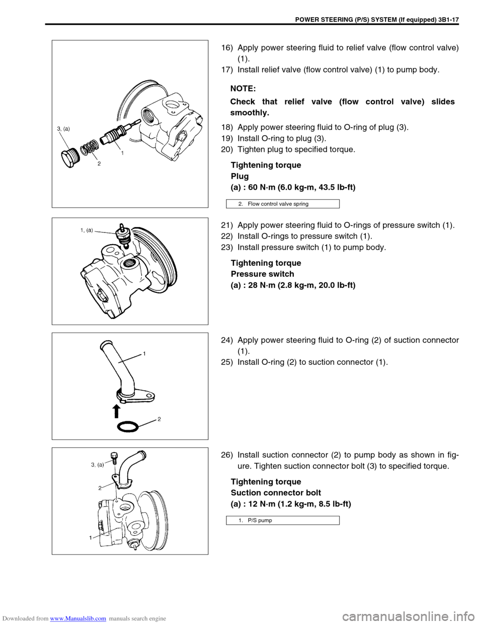
16) Apply power steering fluid to relief valve (flow control valve)
(1).
17) Install relief valve (flow control valve) (1) to pump body.
18) Apply power steering fluid to O-ring of plug (3).
19) Install O-ring to plug (3).
20) Tighten plug to specified torque.
Tightening torque
Plug
(a) : 60 N·m (6.0 kg-m, 43.5 lb-ft)
21) Apply power steering fluid to O-rings of pressure switch (1).
22) Install O-rings to pressure switch (1).
23) Install pressure switch (1) to pump body.
Tightening torque
Pressure switch
(a) : 28 N·m (2.8 kg-m, 20.0 lb-ft)
24) Apply power steering fluid to O-ring (2) of suction connector
(1).
25) Install O-ring (2) to suction connector (1).
26) Install suction connector (2) to pump body as shown in fig-
ure. Tighten suction connector bolt (3) to specified torque.
Tightening torque
Suction connector bolt
(a) : 12 N·m (1.2 kg-m, 8.5 lb-ft) NOTE:
Check that relief valve (flow control valve) slides
smoothly.
2. Flow control valve spring
1. P/S pump