service SUZUKI JIMNY 2005 3.G Service Manual Online
[x] Cancel search | Manufacturer: SUZUKI, Model Year: 2005, Model line: JIMNY, Model: SUZUKI JIMNY 2005 3.GPages: 687, PDF Size: 13.38 MB
Page 360 of 687
Downloaded from www.Manualslib.com manuals search engine ENGINE GENERAL INFORMATION AND DIAGNOSIS 6-3
General Information
Statement on Cleanliness and Care
An automobile engine is a combination of many machined, honed, polished and lapped surfaces with tolerances
that are measured in the thousands of an millimeter (ten thousands of an inch).
Accordingly, when any internal engine parts are serviced, care and cleanliness are important.
Throughout this section, it should be understood that proper cleaning and protection of machined surfaces and
friction areas is part of the repair procedure. This is considered standard shop practice even if not specifically
stated.
A liberal coating of engine oil should be applied to friction areas during assembly to protect and lubricate the
surfaces on initial operation.
Whenever valve train components, pistons, piston rings, connecting rods, rod bearings, and crankshaft jour-
nal bearings are removed for service, they should be retained in order.
At the time of installation, they should be installed in the same locations and with the same mating surfaces
as when removed.
Battery cables should be disconnected before any major work is performed on the engine.
Failure to disconnect cables may result in damage to wire harness or other electrical parts.
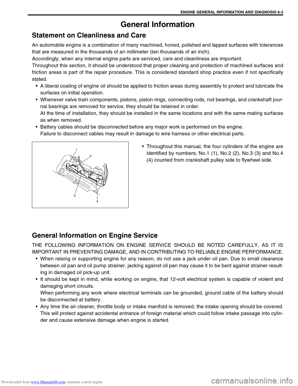
Throughout this manual, the four cylinders of the engine are
identified by numbers; No.1 (1), No.2 (2), No.3 (3) and No.4
(4) counted from crankshaft pulley side to flywheel side.
General Information on Engine Service
THE FOLLOWING INFORMATION ON ENGINE SERVICE SHOULD BE NOTED CAREFULLY, AS IT IS
IMPORTANT IN PREVENTING DAMAGE, AND IN CONTRIBUTING TO RELIABLE ENGINE PERFORMANCE.
When raising or supporting engine for any reason, do not use a jack under oil pan. Due to small clearance
between oil pan and oil pump strainer, jacking against oil pan may cause it to be bent against strainer result-
ing in damaged oil pick-up unit.
It should be kept in mind, while working on engine, that 12-volt electrical system is capable of violent and
damaging short circuits.
When performing any work where electrical terminals can be grounded, ground cable of the battery should
be disconnected at battery.
Any time the air cleaner, throttle body or intake manifold is removed, the intake opening should be covered.
This will protect against accidental entrance of foreign material which could follow intake passage into cylin-
der and cause extensive damage when engine is started.
Page 361 of 687
Downloaded from www.Manualslib.com manuals search engine 6-4 ENGINE GENERAL INFORMATION AND DIAGNOSIS
Precaution on fuel system service
Work must be done with no smoking, in a well-ventilated
area and away from any open flames.
As fuel feed line (between fuel pump and fuel delivery pipe)
is still under high fuel pressure even after engine was
stopped, loosening or disconnecting fuel feed line directly
may cause dangerous spout of fuel to occur where loosened
or disconnected.
Before loosening or disconnecting fuel feed line, make sure
to release fuel pressure according to “FUEL PRESSURE
RELIEF PROCEDURE”. A small amount of fuel may be
released after the fuel line is disconnected. In order to
reduce the chance of personal injury, cover the fitting to be
disconnected with a shop cloth. Put that cloth in an approved
container when disconnection is completed.
Never run engine with fuel pump relay disconnected when
engine and exhaust system are hot.
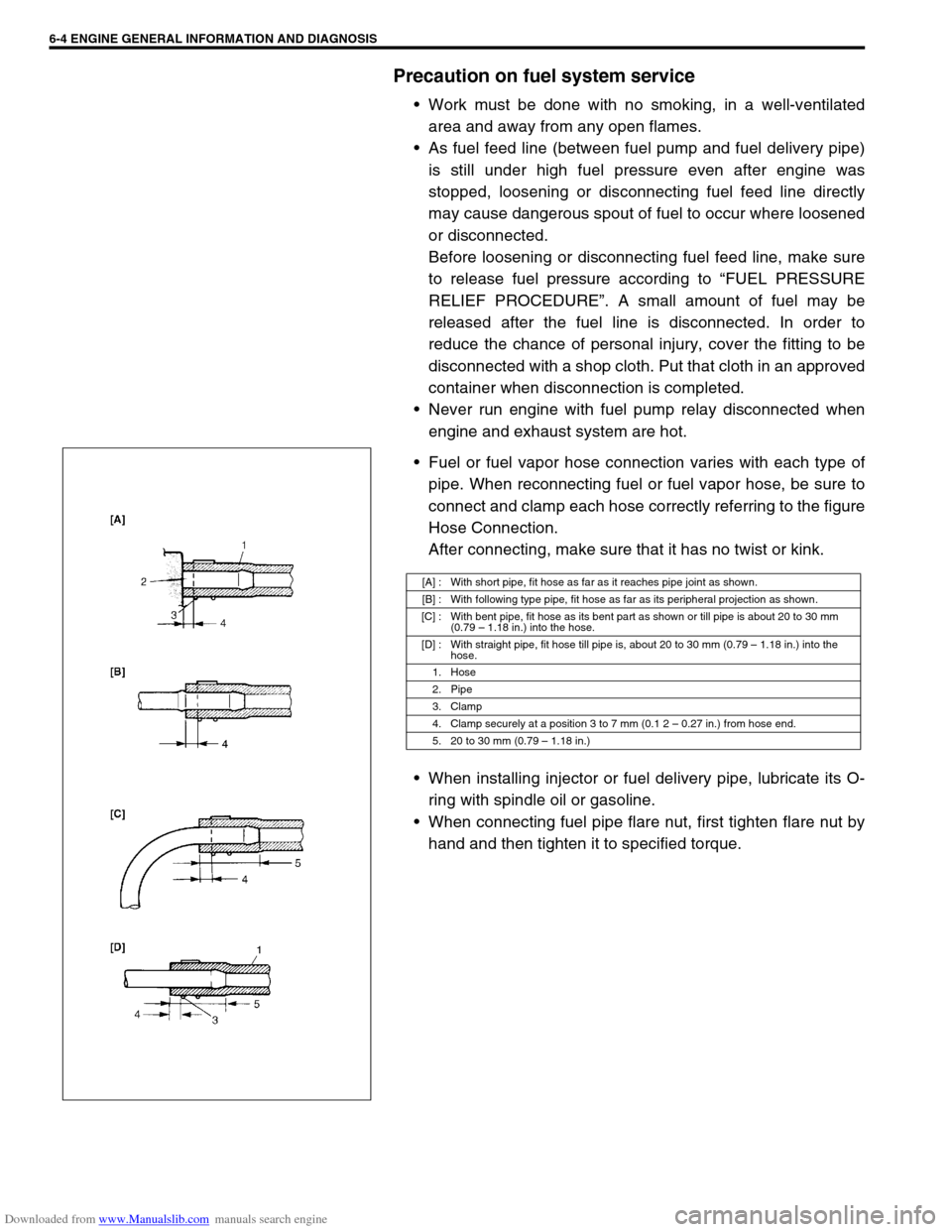
Fuel or fuel vapor hose connection varies with each type of
pipe. When reconnecting fuel or fuel vapor hose, be sure to
connect and clamp each hose correctly referring to the figure
Hose Connection.
After connecting, make sure that it has no twist or kink.
When installing injector or fuel delivery pipe, lubricate its O-
ring with spindle oil or gasoline.
When connecting fuel pipe flare nut, first tighten flare nut by
hand and then tighten it to specified torque.
[A] : With short pipe, fit hose as far as it reaches pipe joint as shown.
[B] : With following type pipe, fit hose as far as its peripheral projection as shown.
[C] : With bent pipe, fit hose as its bent part as shown or till pipe is about 20 to 30 mm
(0.79 – 1.18 in.) into the hose.
[D] : With straight pipe, fit hose till pipe is, about 20 to 30 mm (0.79 – 1.18 in.) into the
hose.
1. Hose
2. Pipe
3. Clamp
4. Clamp securely at a position 3 to 7 mm (0.1 2 – 0.27 in.) from hose end.
5. 20 to 30 mm (0.79 – 1.18 in.)
Page 362 of 687
Downloaded from www.Manualslib.com manuals search engine ENGINE GENERAL INFORMATION AND DIAGNOSIS 6-5
Fuel pressure relief procedure
After making sure that engine is cold, release fuel pressure as fol-
lows.
1) Place transmission gear shift lever in “Neutral” (Shift selector
lever to “P” range for A/T model), set parking brake, and
block drive wheels.
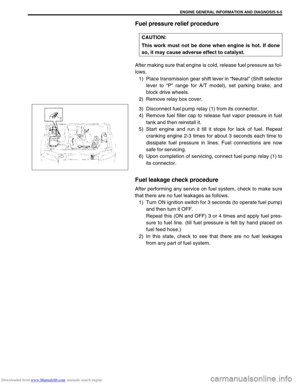
2) Remove relay box cover.
3) Disconnect fuel pump relay (1) from its connector.
4) Remove fuel filler cap to release fuel vapor pressure in fuel
tank and then reinstall it.
5) Start engine and run it till it stops for lack of fuel. Repeat
cranking engine 2-3 times for about 3 seconds each time to
dissipate fuel pressure in lines. Fuel connections are now
safe for servicing.
6) Upon completion of servicing, connect fuel pump relay (1) to
its connector.
Fuel leakage check procedure
After performing any service on fuel system, check to make sure
that there are no fuel leakages as follows.
1) Turn ON ignition switch for 3 seconds (to operate fuel pump)
and then turn it OFF.
Repeat this (ON and OFF) 3 or 4 times and apply fuel pres-
sure to fuel line. (till fuel pressure is felt by hand placed on
fuel feed hose.)
2) In this state, check to see that there are no fuel leakages
from any part of fuel system. CAUTION:
This work must not be done when engine is hot. If done
so, it may cause adverse effect to catalyst.
Page 366 of 687
Downloaded from www.Manualslib.com manuals search engine ENGINE GENERAL INFORMATION AND DIAGNOSIS 6-9
On-Board Diagnostic System (Vehicle without
Immobilizer Indicator Lamp)
ECM diagnosis troubles which may occur in the area including
the following parts when the ignition switch is ON and the engine
is running, and indicates the result by turning on or flashing mal-
function indicator lamp (1).
Heated oxygen sensor (if equipped)
ECT sensor
TP sensor
IAT sensor
MAP sensor
CMP sensor
CKP sensor
Knock sensor
VSS
CPU (Central Processing Unit) of ECM
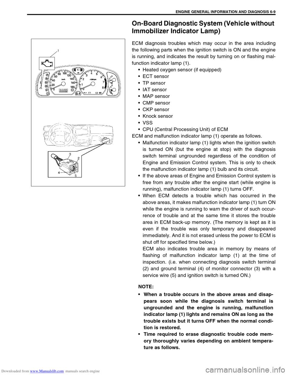
ECM and malfunction indicator lamp (1) operate as follows.
Malfunction indicator lamp (1) lights when the ignition switch
is turned ON (but the engine at stop) with the diagnosis
switch terminal ungrounded regardless of the condition of
Engine and Emission Control system. This is only to check
the malfunction indicator lamp (1) bulb and its circuit.
If the above areas of Engine and Emission Control system is
free from any trouble after the engine start (while engine is
running), malfunction indicator lamp (1) turns OFF.
When ECM detects a trouble which has occurred in the
above areas, it makes malfunction indicator lamp (1) turn ON
while the engine is running to warn the driver of such occur-
rence of trouble and at the same time it stores the trouble
area in ECM back-up memory. (The memory is kept as it is
even if the trouble was only temporary and disappeared
immediately. And it is not erased unless the power to ECM is
shut off for specified time below.)
ECM also indicates trouble area in memory by means of
flashing of malfunction indicator lamp (1) at the time of
inspection. (i.e. when connecting diagnosis switch terminal
(2) and ground terminal (4) of monitor connector (3) with a
service wire (5) and ignition switch is turned ON.)
NOTE:
When a trouble occurs in the above areas and disap-
pears soon while the diagnosis switch terminal is
ungrounded and the engine is running, malfunction
indicator lamp (1) lights and remains ON as long as the
trouble exists but it turns OFF when the normal condi-
tion is restored.
Time required to erase diagnostic trouble code mem-
ory thoroughly varies depending on ambient tempera-
ture as follows.
Page 367 of 687

Downloaded from www.Manualslib.com manuals search engine 6-10 ENGINE GENERAL INFORMATION AND DIAGNOSIS
Precaution in Diagnosing Trouble
Don’t disconnect couplers from ECM, battery cable at battery, ECM ground wire harness from engine or
main fuse before confirming diagnostic information (DTC, freeze frame data, etc.) stored in ECM memory.
Such disconnection will erase memorized information in ECM memory.
Diagnostic information stored in ECM memory can be cleared as well as checked by using SUZUKI scan
tool or generic scan tool. Before using scan tool, read its Operator’s (Instruction) Manual carefully to have
good understanding as to what functions are available and how to use it.
Priorities for diagnosing troubles (Vehicle with Immobilizer indicator lamp).
If multiple diagnostic trouble codes (DTCs) are stored, proceed to the flow table of the DTC which has
detected earliest in the order and follow the instruction in that table.
If no instructions are given, troubleshoot diagnostic trouble codes according to the following priorities.
–Diagnostic trouble codes (DTCs) other than DTC P0171/P0172 (Fuel system too lean / too rich), DTC
P0300/P0301/P0302/P0303/P0304 (Misfire detected) and DTC P0400 (EGR flow malfunction)
–DTC P0171/P0172 (Fuel system too lean / too rich) and DTC P0400 (EGR flow malfunction)
–DTC P0300/P0301/P0302/P0303/P0304 (Misfire detected)
Be sure to read “Precautions for Electrical Circuit Service” in Section 0A before inspection and observe what
is written there.
ECM Replacement
When substituting a known-good ECM, check for following conditions. Neglecting this check may cause
damage to a known-good ECM.
–Resistance value of all relays, actuators is as specified respectively.
–MAP sensor and TP sensor are in good condition and none of power circuits of these sensors is shorted
to ground.AMBIENT TEMPERATURE TIME TO CUT POWER TO
ECM
Over 0 °C (32 °F) 60 sec. or longer
Under 0 °C (32 °F)Not specifiable.
Select a place with higher than
0 °C (32 °F) temperature.
Page 371 of 687
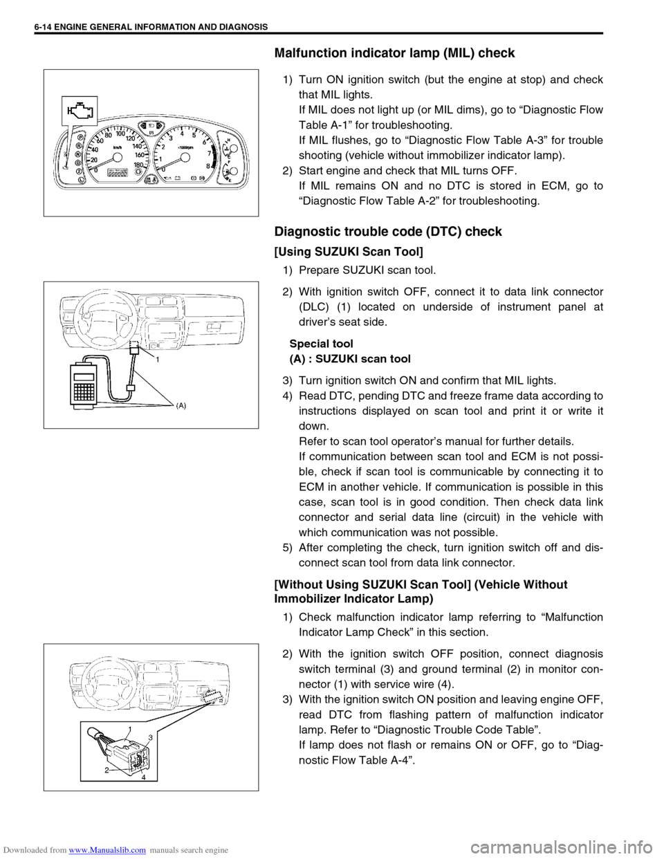
Downloaded from www.Manualslib.com manuals search engine 6-14 ENGINE GENERAL INFORMATION AND DIAGNOSIS
Malfunction indicator lamp (MIL) check
1) Turn ON ignition switch (but the engine at stop) and check
that MIL lights.
If MIL does not light up (or MIL dims), go to “Diagnostic Flow
Table A-1” for troubleshooting.
If MIL flushes, go to “Diagnostic Flow Table A-3” for trouble
shooting (vehicle without immobilizer indicator lamp).
2) Start engine and check that MIL turns OFF.
If MIL remains ON and no DTC is stored in ECM, go to
“Diagnostic Flow Table A-2” for troubleshooting.
Diagnostic trouble code (DTC) check
[Using SUZUKI Scan Tool]
1) Prepare SUZUKI scan tool.
2) With ignition switch OFF, connect it to data link connector
(DLC) (1) located on underside of instrument panel at
driver’s seat side.
Special tool
(A) : SUZUKI scan tool
3) Turn ignition switch ON and confirm that MIL lights.
4) Read DTC, pending DTC and freeze frame data according to
instructions displayed on scan tool and print it or write it
down.
Refer to scan tool operator’s manual for further details.
If communication between scan tool and ECM is not possi-
ble, check if scan tool is communicable by connecting it to
ECM in another vehicle. If communication is possible in this
case, scan tool is in good condition. Then check data link
connector and serial data line (circuit) in the vehicle with
which communication was not possible.
5) After completing the check, turn ignition switch off and dis-
connect scan tool from data link connector.
[Without Using SUZUKI Scan Tool] (Vehicle Without
Immobilizer Indicator Lamp)
1) Check malfunction indicator lamp referring to “Malfunction
Indicator Lamp Check” in this section.
2) With the ignition switch OFF position, connect diagnosis
switch terminal (3) and ground terminal (2) in monitor con-
nector (1) with service wire (4).
3) With the ignition switch ON position and leaving engine OFF,
read DTC from flashing pattern of malfunction indicator
lamp. Refer to “Diagnostic Trouble Code Table”.
If lamp does not flash or remains ON or OFF, go to “Diag-
nostic Flow Table A-4”.
Page 372 of 687

Downloaded from www.Manualslib.com manuals search engine ENGINE GENERAL INFORMATION AND DIAGNOSIS 6-15
4) After completing the check, turn the ignition switch OFF posi-
tion and disconnect service wire from monitor coupler.
Diagnostic trouble code (DTC) clearance
[Using SUZUKI Scan Tool]
1) Connect SUZUKI scan tool to data link connector in the
same manner as when making this connection for DTC
check.
2) Turn ignition switch ON.
3) Erase DTC and pending DTC according to instructions dis-
played on scan tool. Refer to scan tool operator’s manual for
further details.
4) After completing the clearance, turn ignition switch off and
disconnect scan tool from data link connector.
[Without Using SUZUKI Scan Tool]
1) Turn the ignition switch OFF position.
2) Disconnect battery negative cable for specified time below to
erase diagnostic trouble code stored in ECM memory and
reconnect it.
Time required to erase DTC NOTE:
If abnormality or malfunction lies in two or more areas,
malfunction indicator lamp indicates applicable codes
three times each.
And flashing of these codes is repeated as long as
diagnosis terminal is grounded and ignition switch is
held at ON position.
Take a note of diagnostic trouble code indicated first.
NOTE:
DTC and freeze frame data stored in ECM memory are
also cleared in following cases. Be careful not to clear
them before keeping their record.
When power to ECM is cut off (by disconnecting bat-
tery cable, removing fuse or disconnecting ECM con-
nectors)
When the same malfunction (DTC) is not detected
again during 40 engine warm-up cycles.
Ambient temperature Time to cut power to ECM
Over 0 °C (32 °F) 30 sec. or longer
Under 0 °C (32 °F)Not specifiable.
Select a place with higher than
0 °C (32 °F) temperature.
Page 401 of 687

Downloaded from www.Manualslib.com manuals search engine 6-44 ENGINE GENERAL INFORMATION AND DIAGNOSIS
Table A-2 Malfunction Indicator Lamp Circuit Check - Lamp Remains “ON”
after Engine Starts
WIRING DIAGRAM / CIRCUIT DESCRIPTION
Refer to table A-1.
INSPECTION
2 ECM Power and Ground Circuit Check
Does engine start?Go to Step 3. Go to “Table A-5 ECM
Power and Ground Circuit
Check”.
If engine is not cranked,
go to “Diagnosis” in Sec-
tion 8G.
3 MIL Circuit Check
1) Turn ignition switch OFF and disconnect
connectors from ECM.
2) Check for proper connection to ECM at ter-
minal E18-2 (Case of TYPE A) (See NOTE)
or E17-9 (Case of TYPE B) (See NOTE).
3) If OK, then using service wire, ground termi-
nal E18-2 (Case of TYPE A) (See NOTE) or
E17-9 (Case of TYPE B) (See NOTE) in
connector disconnected.
Does MIL turn on at ignition switch ON?Substitute a known-good
ECM and recheck.Bulb burned out, “V/Y”
wire circuit open or “P”
wire shorted to ground. Step Action Yes No
Step Action Yes No
1 Diagnostic Trouble Code (DTC) check
1) Check DTC referring to DTC CHECK sec-
tion.
Is there any DTC(s)?Go to Step 2 of “Engine
Diag. Flow Table”.Go to Step 2.
2DTC check
1) Start engine and recheck DTC while engine
running.
Is there any DTC(s)?Go to Step 3.
3 MIL Circuit check
1) Turn OFF ignition switch.
2) Disconnect connectors from ECM.
Does MIL turn ON at ignition switch ON?“V/Y” wire circuit shorted
to ground.Substitute a known-good
ECM and recheck.
Page 404 of 687
![SUZUKI JIMNY 2005 3.G Service Manual Online Downloaded from www.Manualslib.com manuals search engine ENGINE GENERAL INFORMATION AND DIAGNOSIS 6-47
[A] Fig. 1 for Step 2 and 3 / [B] Fig. 2 for Step 2 / [C] Fig. 3 for Step 23 Fuse Check
Is main � SUZUKI JIMNY 2005 3.G Service Manual Online Downloaded from www.Manualslib.com manuals search engine ENGINE GENERAL INFORMATION AND DIAGNOSIS 6-47
[A] Fig. 1 for Step 2 and 3 / [B] Fig. 2 for Step 2 / [C] Fig. 3 for Step 23 Fuse Check
Is main �](/img/20/7588/w960_7588-403.png)
Downloaded from www.Manualslib.com manuals search engine ENGINE GENERAL INFORMATION AND DIAGNOSIS 6-47
[A] Fig. 1 for Step 2 and 3 / [B] Fig. 2 for Step 2 / [C] Fig. 3 for Step 23 Fuse Check
Is main “FI” fuse in good condition? See Fig. 1.Go to Step 4. Check for
short in cir-
cuits con-
nected to this
fuse.
4 ECM Power Circuit Check
1) Turn OFF ignition switch, disconnect connectors from ECM and
install main relay.
2) Check for proper connection to ECM at terminals E17-9 (Case of
TYPE A) (See NOTE) or E18-11 (Case of TYPE B) (See NOTE),
E18-10, E18-5 and E18-6.
3) If OK, then measure voltage between terminal E18-10 and ground,
E17-9 (Case of TYPE A) (See NOTE) or E18-11 (Case of TYPE B)
(See NOTE) and ground with ignition switch ON.
Is each voltage 10 – 14 V?Go to Step 5.“B/W”, “Or” or
“Bl/B” circuit
open.
5 ECM Power Circuit Check
1) Using service wire, ground terminal E18-10 and measure voltage
between terminal E18-5 and ground at ignition switch ON.
Is it 10 – 14 V?Check
ground cir-
cuits “B” and
“B/R” for
open.
If OK, then
substitute a
known-good
ECM and
recheck.Go to Step 6.
6 Is operating sound of main relay heard in Step 1? Go to Step 7.“Bl/B” or “B/
R” wire open.
7 Main Relay Check
1) Check main relay according to procedure in Step 2.
Is main relay in good condition?“Or” or “Bl/B”
wire open.Replace main
relay. Step Action Yes No
2.“F1” fuse
Page 409 of 687
![SUZUKI JIMNY 2005 3.G Service Manual Online Downloaded from www.Manualslib.com manuals search engine 6-52 ENGINE GENERAL INFORMATION AND DIAGNOSIS
[A] Fig. 1 for Step 2 / [B] Fig. 2 for Step 3 / [C] Fig. 3 for Step 63 Check Wire Harness.
1) Dis SUZUKI JIMNY 2005 3.G Service Manual Online Downloaded from www.Manualslib.com manuals search engine 6-52 ENGINE GENERAL INFORMATION AND DIAGNOSIS
[A] Fig. 1 for Step 2 / [B] Fig. 2 for Step 3 / [C] Fig. 3 for Step 63 Check Wire Harness.
1) Dis](/img/20/7588/w960_7588-408.png)
Downloaded from www.Manualslib.com manuals search engine 6-52 ENGINE GENERAL INFORMATION AND DIAGNOSIS
[A] Fig. 1 for Step 2 / [B] Fig. 2 for Step 3 / [C] Fig. 3 for Step 63 Check Wire Harness.
1) Disconnect IAT sensor connector with igni-
tion switch OFF.
2) Check for proper connection to IAT sensor
at “Lg/B” and “B/Bl” wire terminals.
See Fig. 2.
3) If OK, then with ignition switch ON.
Is voltage applied to “Lg/B” wire terminal about
4 – 6 V?Go to Step 5.“Lg/B” wire open or
shorted to power, or poor
E19-15 connection.
If wire and connection are
OK, substitute a known-
good ECM and recheck.
4 Does scan tool indicate –40 °C (–40 °F) at Step
2.Go to Step 6. Go to Step 5.
5 Check Wire Harness
1) Check intake air temp. displayed on scan
tool with ignition switch ON.
Is –40 °C (–40 °F) indicated?Replace IAT sensor.“Lg/B” wire shorted to
ground.
If wire is OK, substitute a
known-good ECM and
recheck.
6 Check Wire Harness.
1) Using service wire, connect IAT sensor con-
nector terminals.
2) Check intake air temp. displayed on scan
tool with ignition switch ON. See Fig. 3.
Is 119 °C (246 °F) indicated?Replace IAT sensor.“Lg/B” wire open or poor
E19-10 connection.
If wire and connection are
OK, substitute a known-
good ECM and recheck. Step Action Yes No