BOX SUZUKI JIMNY 2005 3.G Service Workshop Manual
[x] Cancel search | Manufacturer: SUZUKI, Model Year: 2005, Model line: JIMNY, Model: SUZUKI JIMNY 2005 3.GPages: 687, PDF Size: 13.38 MB
Page 4 of 687
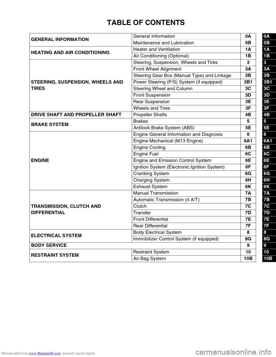
Downloaded from www.Manualslib.com manuals search engine TABLE OF CONTENTS
GENERAL INFORMATIONGeneral Information0A0A
Maintenance and Lubrication0B
0B
HEATING AND AIR CONDITIONINGHeater and Ventilation1A
1A
Air Conditioning (Optional)1B
1B
STEERING, SUSPENSION, WHEELS AND
TIRESSteering, Suspension, Wheels and Tires3
3
Front Wheel Alignment3A
3A
Steering Gear Box (Manual Type) and Linkage3B
3B
Power Steering (P/S) System (if equipped)3B1
3B1
Steering Wheel and Column3C
3C
Front Suspension3D
3D
Rear Suspension3E
3E
Wheels and Tires3F
3F
DRIVE SHAFT AND PROPELLER SHAFT
Propeller Shafts4B
4B
BRAKE SYSTEMBrakes5
5
Antilock Brake System (ABS)5E
5E
ENGINEEngine General Information and Diagnosis6
6
Engine Mechanical (M13 Engine)6A1
6A1
Engine Cooling6B
6B
Engine Fuel6C
6C
Engine and Emission Control System6E
6E
Ignition System (Electronic Ignition System)6F
6F
Cranking System6G
6G
Charging System6H
6H
Exhaust System6K
6K
TRANSMISSION, CLUTCH AND
DIFFERENTIALManual Transmission7A
7A
Automatic Transmission (4 A/T)7B
7B
Clutch7C
7C
Transfer7D
7D
Front Differential7E
7E
Rear Differential7F
7F
ELECTRICAL SYSTEMBody Electrical System8
8
Immobilizer Control System (if equipped)8G
8G
BODY SERVICE9
9
RESTRAINT SYSTEMRestraint System10
10
Air Bag System10B
10B
Page 49 of 687
Downloaded from www.Manualslib.com manuals search engine 0B-18 MAINTENANCE AND LUBRICATION
Steering System
INSPECTION
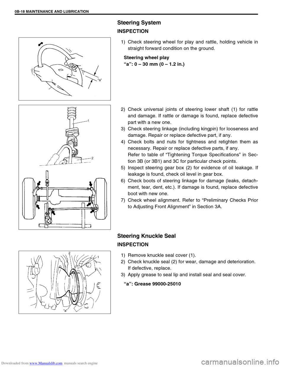
1) Check steering wheel for play and rattle, holding vehicle in
straight forward condition on the ground.
Steering wheel play
“a”: 0 – 30 mm (0 – 1.2 in.)
2) Check universal joints of steering lower shaft (1) for rattle
and damage. If rattle or damage is found, replace defective
part with a new one.
3) Check steering linkage (including kingpin) for looseness and
damage. Repair or replace defective part, if any.
4) Check bolts and nuts for tightness and retighten them as
necessary. Repair or replace defective parts, if any.
Refer to table of “Tightening Torque Specifications” in Sec-
tion 3B (or 3B1) and 3C for particular check points.
5) Inspect steering gear box (2) for evidence of oil leakage. If
leakage is found, check oil level in gear box.
6) Check boots of steering linkage for damage (leaks, detach-
ment, tear, dent, etc.). If damage is found, replace defective
boot with new one.
7) Check wheel alignment. Refer to “Preliminary Checks Prior
to Adjusting Front Alignment” in Section 3A.
Steering Knuckle Seal
INSPECTION
1) Remove knuckle seal cover (1).
2) Check knuckle seal (2) for wear, damage and deterioration.
If defective, replace.
3) Apply grease to seal lip and install seal and seal cover.
“a”: Grease 99000-25010
Page 55 of 687
Downloaded from www.Manualslib.com manuals search engine 1A-2 HEATER AND VENTILATION
General Description
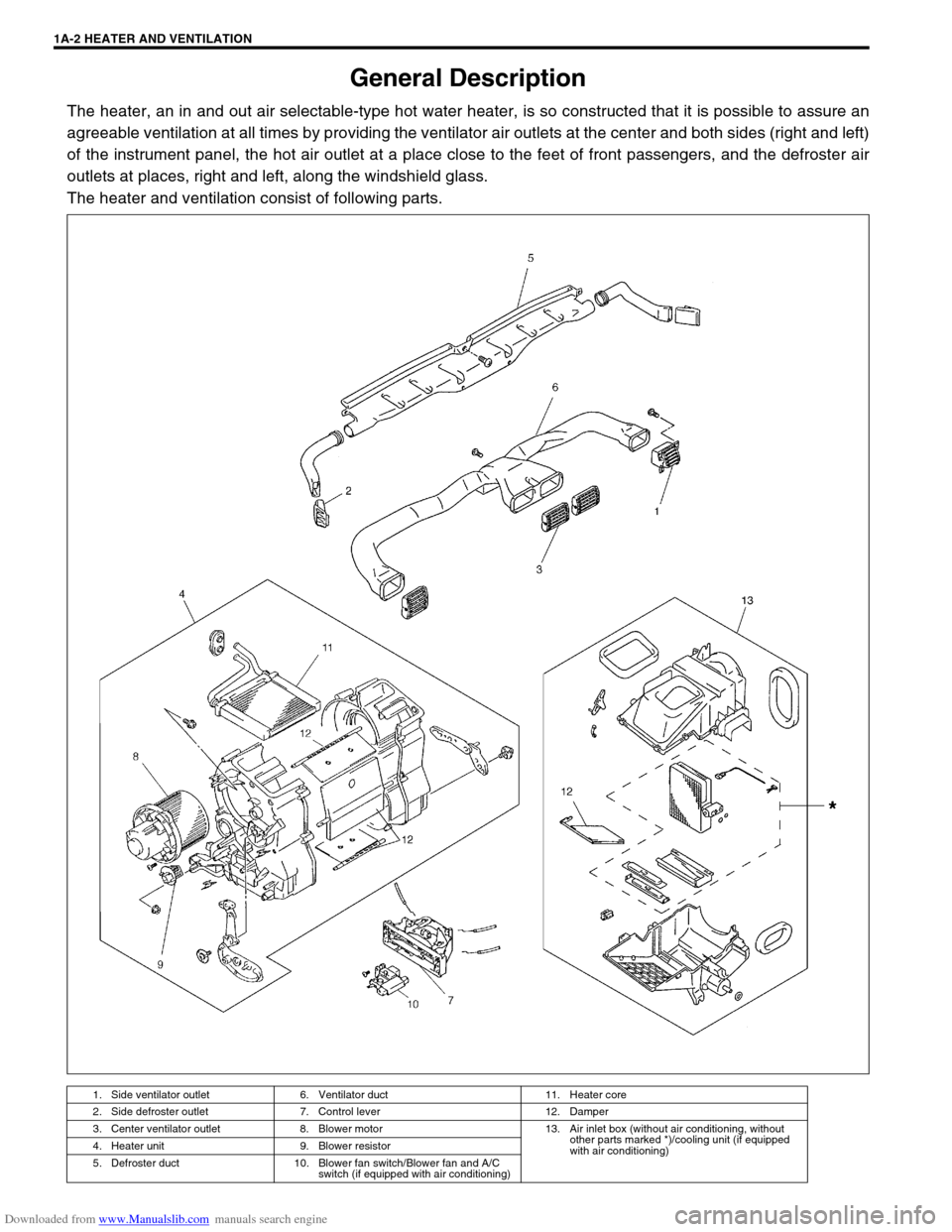
The heater, an in and out air selectable-type hot water heater, is so constructed that it is possible to assure an
agreeable ventilation at all times by providing the ventilator air outlets at the center and both sides (right and left)
of the instrument panel, the hot air outlet at a place close to the feet of front passengers, and the defroster air
outlets at places, right and left, along the windshield glass.
The heater and ventilation consist of following parts.
1. Side ventilator outlet 6. Ventilator duct 11. Heater core
2. Side defroster outlet 7. Control lever 12. Damper
3. Center ventilator outlet 8. Blower motor 13. Air inlet box (without air conditioning, without
other parts marked *)/cooling unit (if equipped
with air conditioning) 4. Heater unit 9. Blower resistor
5. Defroster duct 10. Blower fan switch/Blower fan and A/C
switch (if equipped with air conditioning)
Page 56 of 687
Downloaded from www.Manualslib.com manuals search engine HEATER AND VENTILATION 1A-3
Diagnosis
Diagnosis Table
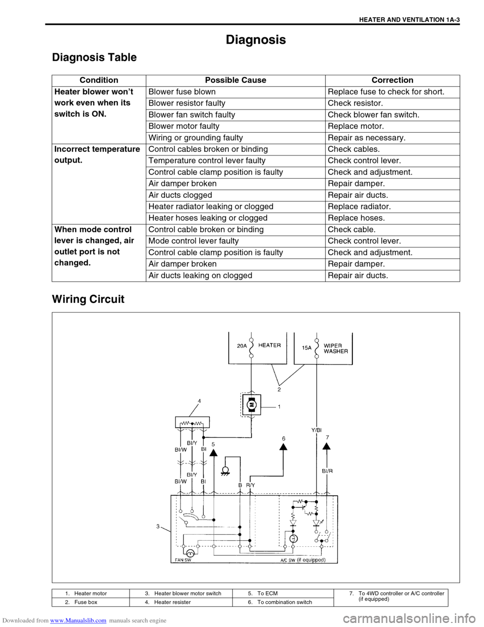
Wiring Circuit
Condition Possible Cause Correction
Heater blower won’t
work even when its
switch is ON.Blower fuse blown Replace fuse to check for short.
Blower resistor faulty Check resistor.
Blower fan switch faulty Check blower fan switch.
Blower motor faulty Replace motor.
Wiring or grounding faulty Repair as necessary.
Incorrect temperature
output.Control cables broken or binding Check cables.
Temperature control lever faulty Check control lever.
Control cable clamp position is faulty Check and adjustment.
Air damper broken Repair damper.
Air ducts clogged Repair air ducts.
Heater radiator leaking or clogged Replace radiator.
Heater hoses leaking or clogged Replace hoses.
When mode control
lever is changed, air
outlet port is not
changed.Control cable broken or binding Check cable.
Mode control lever faulty Check control lever.
Control cable clamp position is faulty Check and adjustment.
Air damper broken Repair damper.
Air ducts leaking on clogged Repair air ducts.
1. Heater motor 3. Heater blower motor switch 5. To ECM 7. To 4WD controller or A/C controller
(if equipped)
2. Fuse box 4. Heater resister 6. To combination switch
Page 58 of 687
Downloaded from www.Manualslib.com manuals search engine HEATER AND VENTILATION 1A-5
Heater Blower Resistor
REMOVAL
1) Disconnect negative (–) cable at battery.
2) Disable air bag system, if equipped.
Refer to “Disabling Air Bag System” in Section 10B.
3) Disconnect resistor coupler.
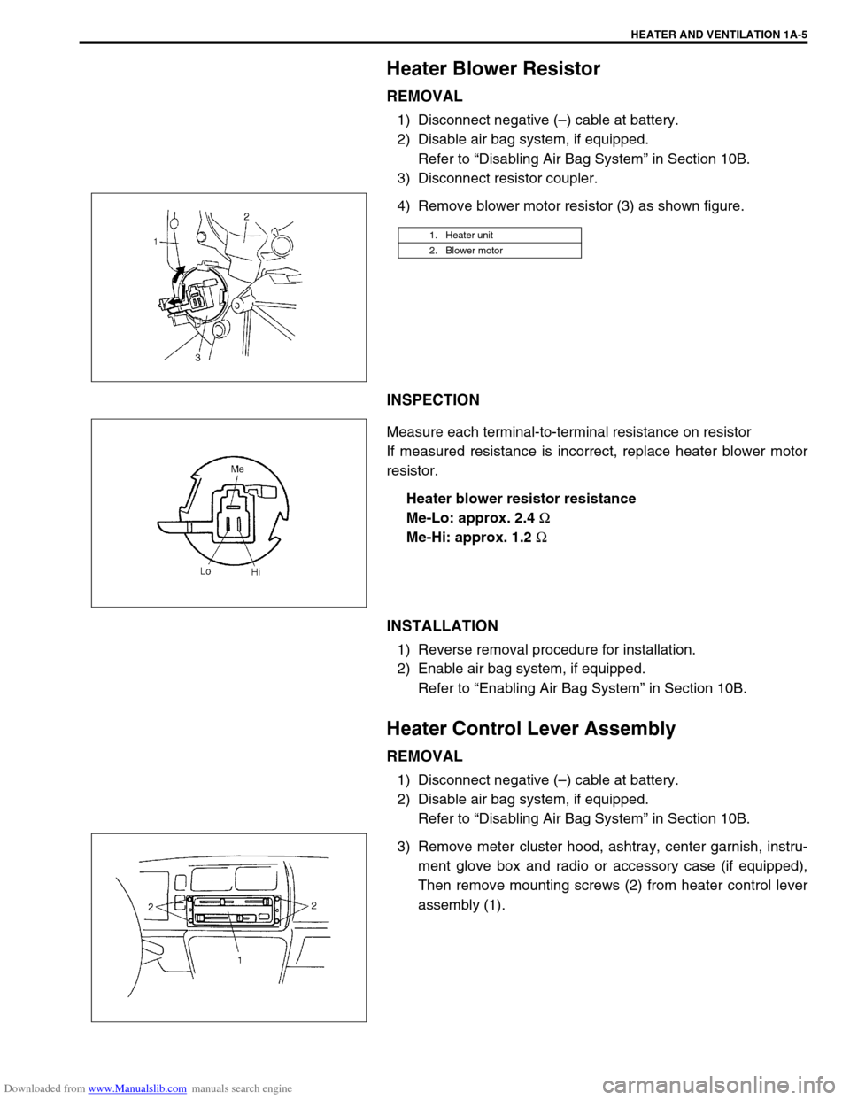
4) Remove blower motor resistor (3) as shown figure.
INSPECTION
Measure each terminal-to-terminal resistance on resistor
If measured resistance is incorrect, replace heater blower motor
resistor.
Heater blower resistor resistance
Me-Lo: approx. 2.4
Ω
Me-Hi: approx. 1.2
Ω
INSTALLATION
1) Reverse removal procedure for installation.
2) Enable air bag system, if equipped.
Refer to “Enabling Air Bag System” in Section 10B.
Heater Control Lever Assembly
REMOVAL
1) Disconnect negative (–) cable at battery.
2) Disable air bag system, if equipped.
Refer to “Disabling Air Bag System” in Section 10B.
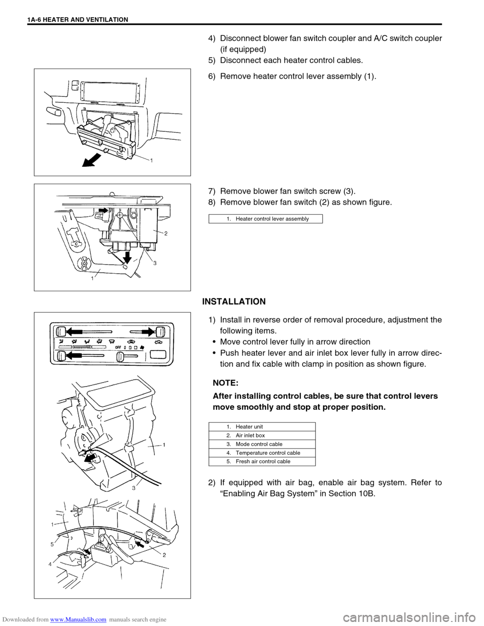
3) Remove meter cluster hood, ashtray, center garnish, instru-
ment glove box and radio or accessory case (if equipped),
Then remove mounting screws (2) from heater control lever
assembly (1).
1. Heater unit
2. Blower motor
Page 59 of 687
Downloaded from www.Manualslib.com manuals search engine 1A-6 HEATER AND VENTILATION
4) Disconnect blower fan switch coupler and A/C switch coupler
(if equipped)
5) Disconnect each heater control cables.
6) Remove heater control lever assembly (1).
7) Remove blower fan switch screw (3).
8) Remove blower fan switch (2) as shown figure.
INSTALLATION
1) Install in reverse order of removal procedure, adjustment the
following items.
Move control lever fully in arrow direction
Push heater lever and air inlet box lever fully in arrow direc-
tion and fix cable with clamp in position as shown figure.
2) If equipped with air bag, enable air bag system. Refer to
“Enabling Air Bag System” in Section 10B.
1. Heater control lever assembly
NOTE:
After installing control cables, be sure that control levers
move smoothly and stop at proper position.
1. Heater unit
2. Air inlet box
3. Mode control cable
4. Temperature control cable
5. Fresh air control cable
Page 66 of 687

Downloaded from www.Manualslib.com manuals search engine AIR CONDITIONING (OPTIONAL) 1B-5
Diagnosis
General Diagnosis Table
Condition Possible Cause Correction
Cool air won’t come
out (A/C system won’t
operative)No refrigerant Perform recover, evacuation and charging.
Fuse blown Check fuses in main and circuit fuse
boxes, and check short circuit to ground.
A/C switch faulty Check A/C switch.
Blower fan switch faulty Check blower fan switch referring to Sec-
tion 1A.
A/C evaporator thermistor faulty Check A/C evaporator thermistor.
Dual pressure switch faulty Check dual pressure switch.
Wiring or grounding faulty Repair as necessary.
ECT sensor faulty Check ECT sensor referring to Section 6E.
ECM and its circuit faulty Check ECM and its circuit referring to Sec-
tion 6E.
4WD controller faulty Check 4WD controller referring to Section
3D.
Cool air won’t come
out (A/C compressor
won't operative)ECM faulty Check ECM and its circuit referring to Sec-
tion 6E.
Magnet clutch faulty Check magnet clutch.
Compressor drive belt loosen or broken Adjust or replace drive belt.
Compressor faulty Check compressor.
Cool air won’t come
out (A/C condenser
cooling fan motor
won’t operative)Fuse blown Check “A/C” fuse in main fuse box, and
check short circuit to ground.
Wiring or grounding faulty Repair as necessary.
Condenser cooling fan motor relay
faultyCheck condenser cooling fan motor relay.
Condenser cooling fan motor faulty Check condenser cooling fan motor.
Cool air won’t come
out (Blower fan motor
won’t operative)Fuse blown Check fuses in main and circuit fuse
boxes, and check short circuit to ground.
Blower fan motor resistor faulty Check blower fan motor resistor referring
to Section 1A.
Blower fan switch faulty Check blower fan switch referring to Sec-
tion 1A.
Wiring or grounding faulty Repair as necessary.
Blower fan motor faulty Check blower fan motor referring to Sec-
tion 1A.
Page 67 of 687

Downloaded from www.Manualslib.com manuals search engine 1B-6 AIR CONDITIONING (OPTIONAL)
Cool air won’t come
out or insufficient
cooling (A/C system
normal operative)Insufficient or excessive charge of
refrigerantCheck charge of refrigerant and system for
leaks.
Condenser clogged Check condenser.
A/C evaporator clogged or frosted Check A/C evaporator and A/C evaporator
thermistor.
A/C evaporator thermistor faulty Check A/C evaporator thermistor.
Expansion valve faulty Check expansion valve.
Receiver / dryer clogged Check receiver / dryer.
Compressor drive belt loosen or broken Adjust or replace drive belt.
Magnetic clutch faulty Check magnetic clutch.
Compressor faulty Check compressor.
Air in A/C system Replace receiver / dryer, and perform
evacuation and charging.
Air leaking from cooling unit or air duct Repair as necessary.
Heater and ventilation system faulty Check air inlet box (cooling unit), heater
control lever assembly and heater unit
referring to Section 1A.
Blower fan motor faulty Check blower fan motor referring to Sec-
tion 1A.
Excessive compressor oil existing in
A/C systemPull out compressor oil in A/C system cir-
cuit, and replace compressor.
Cool air won’t come
out only intermittentlyWiring connection faulty Repair as necessary.
Expansion valve faulty Check expansion valve.
Excessive moisture in A/C system Replace receiver / dryer, and perform
evacuation and charging.
Magnetic clutch faulty Check magnetic clutch.
Excessive charge of refrigerant Check charge of refrigerant.
Thermal switch faulty Check thermal switch.
Cool air comes out
only at high speedCondenser clogged Check A/C condenser.
Insufficient charge of refrigerant Check charge of refrigerant.
Air in A/C system Replace receiver / dryer, and perform
evacuation and charging.
Compressor drive belt loosen or broken Adjust or replace drive belt.
Compressor faulty Check compressor.
Cool air won’t come
out only at high speedExcessive charge of refrigerant Check charge refrigerant.
A/C evaporator frosted Check A/C evaporator and A/C evaporator
thermistor.
Insufficient velocity of
cooled airA/C evaporator clogged or frosted Check A/C evaporator and A/C evaporator
thermistor.
Air leaking from cooling unit or air duct Repair as necessary.
Blower fan motor faulty Check blower fan motor referring to Sec-
tion 1A.
Wiring or grounding faulty Repair as necessary. Condition Possible Cause Correction
Page 77 of 687
![SUZUKI JIMNY 2005 3.G Service Workshop Manual Downloaded from www.Manualslib.com manuals search engine 1B-16 AIR CONDITIONING (OPTIONAL)
Electronical Diagnosis
Wiring Diagram
[A]: 4WD model 4. Dual pressure switch 9. Thermal switch 14. Circuit fu SUZUKI JIMNY 2005 3.G Service Workshop Manual Downloaded from www.Manualslib.com manuals search engine 1B-16 AIR CONDITIONING (OPTIONAL)
Electronical Diagnosis
Wiring Diagram
[A]: 4WD model 4. Dual pressure switch 9. Thermal switch 14. Circuit fu](/img/20/7588/w960_7588-76.png)
Downloaded from www.Manualslib.com manuals search engine 1B-16 AIR CONDITIONING (OPTIONAL)
Electronical Diagnosis
Wiring Diagram
[A]: 4WD model 4. Dual pressure switch 9. Thermal switch 14. Circuit fuse box
[B]: 2WD model 5. 4WD controller 10. Ignition switch 15. Main fuse box
1. Blower fan motor 6. Condenser cooling fan motor relay 11. A/C evaporator thermistor 16. Generator
2. Blower fan motor resistor 7. Condenser cooling fan motor 12. ECT sensor 17. ECM
3. Blower fan motor switch and A/C switch 8. Compressor 13. Lighting switch
Page 79 of 687
![SUZUKI JIMNY 2005 3.G Service Workshop Manual Downloaded from www.Manualslib.com manuals search engine 1B-18 AIR CONDITIONING (OPTIONAL)
Terminal arrangement of ECM coupler (Viewed from harness side)
1. Blower fan motor 8. Compressor [A]: To “A SUZUKI JIMNY 2005 3.G Service Workshop Manual Downloaded from www.Manualslib.com manuals search engine 1B-18 AIR CONDITIONING (OPTIONAL)
Terminal arrangement of ECM coupler (Viewed from harness side)
1. Blower fan motor 8. Compressor [A]: To “A](/img/20/7588/w960_7588-78.png)
Downloaded from www.Manualslib.com manuals search engine 1B-18 AIR CONDITIONING (OPTIONAL)
Terminal arrangement of ECM coupler (Viewed from harness side)
1. Blower fan motor 8. Compressor [A]: To “A/C” fuse (25A) in main fuse box
2. Dual pressure switch 9. Thermal switch [B]: To “HEATER” fuse (20A) in circuit fuse box
3. A/C switch 10. Main relay [C]: To “FI” fuse (15A) in main fuse box
4. A/C evaporator thermistor 11. Engine earth [D]: 4WD model
5. ECT sensor 12. Blower fan motor switch [E]: 2WD model
6. Condenser cooling fan motor relay 13. 4WD controller
7. Condenser cooling fan motor 14. ECM