ABS SUZUKI SWIFT 2000 1.G RG413 Service Owners Manual
[x] Cancel search | Manufacturer: SUZUKI, Model Year: 2000, Model line: SWIFT, Model: SUZUKI SWIFT 2000 1.GPages: 698, PDF Size: 16.01 MB
Page 368 of 698
ANTILOCK BRAKE SYSTEM (ABS) 5E-43
G SENSOR (FOR 4WD VEHICLE ONLY)
REMOVAL
1) Turn ignition switch OFF and disconnect battery negative
cable.
2) Remove ABS fuse from fuse box.
3) Disconnect ABS hydraulic unit/control module assembly
connector by pulling up lock.
4) Remove center console box.
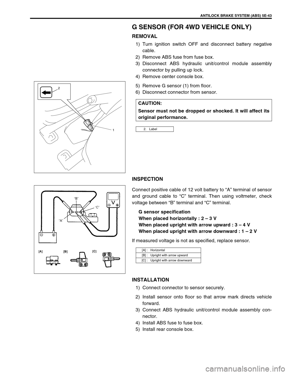
5) Remove G sensor (1) from floor.
6) Disconnect connector from sensor.
INSPECTION
Connect positive cable of 12 volt battery to “A” terminal of sensor
and ground cable to “C” terminal. Then using voltmeter, check
voltage between “B” terminal and “C” terminal.
G sensor specification
When placed horizontally : 2 – 3 V
When placed upright with arrow upward : 3 – 4 V
When placed upright with arrow downward : 1 – 2 V
If measured voltage is not as specified, replace sensor.
INSTALLATION
1) Connect connector to sensor securely.
2) Install sensor onto floor so that arrow mark directs vehicle
forward.
3) Connect ABS hydraulic unit/control module assembly con-
nector.
4) Install ABS fuse to fuse box.
5) Install rear console box.CAUTION:
Sensor must not be dropped or shocked. It will affect its
original performance.
2. Label1
2
[A] : Horizontal
[B] : Upright with arrow upward
[C] : Upright with arrow downward
Page 369 of 698

5E-44 ANTILOCK BRAKE SYSTEM (ABS)
SPECIAL TOOL
09913-65135 09913-75520 09913-75840 09927-18411
Bearing puller Bearing installing tool Sensor ring installer Universal puller
09921-57810 09931-76011 09931-76030
Countershaft holder Tech 1A kit
(See NOTE below.)Mass storage cartridge 16/14 pin DLC cable
09950-78220
Flare nut wrench (10 mm)
NOTE:
This kit includes the following items.
1. Storage case, 2. Operator's manual, 3. Tech 1A, 4. DLC cable, 5. Test lead/probe,
6. Power source cable, 7. DLC cable adaptor, 8. Self-test adaptor
Page 371 of 698
6-2 ENGINE GENERAL INFORMATION AND DIAGNOSIS
ENGINE DIAGNOSIS ......................................... 6-6
GENERAL DESCRIPTION ............................. 6-6
ON-BOARD DIAGNOSTIC SYSTEM
(VEHICLE WITH IMMOBILIZER INDICATOR
LAMP) ............................................................. 6-7
ON-BOARD DIAGNOSTIC SYSTEM
(VEHICLE WITHOUT IMMOBILIZER
INDICATOR LAMP) ...................................... 6-10
PRECAUTION IN DIAGNOSING
TROUBLE ..................................................... 6-11
ENGINE DIAGNOSTIC FLOW TABLE ......... 6-12
CUSTOMER PROBLEM INSPECTION
FORM (EXAMPLE) ................................... 6-14
MALFUNCTION INDICATOR LAMP (MIL)
CHECK...................................................... 6-15
DIAGNOSTIC TROUBLE CODE (DTC)
CHECK...................................................... 6-15
DIAGNOSTIC TROUBLE CODE (DTC)
CLEARANCE ............................................ 6-16
DIAGNOSTIC TROUBLE CODE (DTC)
TABLE ....................................................... 6-17
FAIL-SAFE TABLE.................................... 6-20
VISUAL INSPECTION .............................. 6-22
ENGINE BASIC INSPECTION.................. 6-23
ENGINE DIAGNOSIS TABLE ................... 6-26
SCAN TOOL DATA....................................... 6-31
INSPECTION OF ECM AND ITS
CIRCUITS ..................................................... 6-36
ECM VOLTAGE VALUES TABLE............. 6-37
TERMINAL RESISTANCE TABLE............ 6-43
COMPONENT LOCATION ........................... 6-45
TABLE A-1 MALFUNCTION INDICATOR
LAMP CIRCUIT CHECK - LAMP DOES NOT
COME “ON” AT IGNITION SWITCH ON
(BUT ENGINE AT STOP) ............................. 6-46
TABLE A-2 MALFUNCTION INDICATOR
LAMP CIRCUIT CHECK - LAMP REMAINS
“ON” AFTER ENGINE STARTS ................... 6-47
TABLE A-3 MIL CHECK - MIL FLASHES
AT IGNITION SWITCH ON (VEHICLE
WITHOUT IMMOBILIZER INDICATOR
LAMP) ........................................................... 6-48
TABLE A-4 MIL CHECK - MIL DOES NOT
FLASH OR JUST REMAINS ON EVEN
WITH GROUNDING DIAGNOSIS SWITCH
TERMINAL (VEHICLE WITHOUT
IMMOBILIZER INDICATOR LAMP) .............. 6-48
TABLE A-5 ECM POWER AND GROUND
CIRCUIT CHECK - MIL DOESN’T LIGHT
AT IGNITION SWITCH ON AND ENGINE
DOESN’T START THOUGH IT IS
CRANKED UP .............................................. 6-49
DTC P0105 (DTC NO.11) MANIFOLD
ABSOLUTE PRESSURE (MAP) CIRCUIT
MALFUNCTION ............................................ 6-52
DTC P0110 (DTC NO.18) INTAKE AIR
TEMP. (IAT) CIRCUIT MALFUNCTION ....... 6-55
DTC P0115 (DTC NO.19) ENGINE
COOLANT TEMPERATURE (ECT) CIRCUIT
MALFUNCTION ............................................ 6-57DTC P0120 (DTC NO.13) THROTTLE
POSITION CIRCUIT MALFUNCTION ........... 6-60
DTC P0121 THROTTLE POSITION CIRCUIT
RANGE/PERFORMANCE PROBLEM .......... 6-63
DTC P0130 (DTC NO.14) HEATED OXYGEN
SENSOR (HO2S) CIRCUIT MALFUNCTION
(SENSOR-1) .................................................. 6-66
DTC P0133 HEATED OXYGEN SENSOR
(HO2S) CIRCUIT SLOW RESPONSE
(SENSOR-1) .................................................. 6-68
DTC P0134 HEATED OXYGEN SENSOR
(HO2S) CIRCUIT NO ACTIVITY DETECTED
(SENSOR-1) .................................................. 6-69
DTC P0135 (DTC NO.14) HEATED OXYGEN
SENSOR (HO2S) HEATER CIRCUIT
MALFUNCTION (SENSOR-1) ....................... 6-70
DTC P0136 HEATED OXYGEN SENSOR
(HO2S) CIRCUIT MALFUNCTION
(SENSOR-2) .................................................. 6-72
DTC P0141 HEATED OXYGEN SENSOR
(HO2S) HEATER CIRCUIT MALFUNCTION
(SENSOR-2) .................................................. 6-74
DTC P0171 FUEL SYSTEM TOO LEAN ....... 6-76
DTC P0172 FUEL SYSTEM TOO RICH ....... 6-76
DTC P0300 RANDOM MISFIRE DETECTED
(MISFIRE DETECTED AT 2 OR MORE
CYLINDERS) ................................................. 6-81
DTC P0301 CYLINDER 1 MISFIRE
DETECTED ................................................... 6-81
DTC P0302 CYLINDER 2 MISFIRE
DETECTED ................................................... 6-81
DTC P0303 CYLINDER 3 MISFIRE
DETECTED ................................................... 6-81
DTC P0304 CYLINDER 4 MISFIRE
DETECTED ................................................... 6-81
DTC P0325 (DTC NO.17) KNOCK SENSOR
CIRCUIT MALFUNCTION ............................. 6-86
DTC P0335 (DTC NO.23) CRANKSHAFT
POSITION (CKP) SENSOR CIRCUIT
MALFUNCTION ............................................. 6-88
DTC P0340 (DTC NO.15) CAMSHAFT
POSITION (CMP) SENSOR CIRCUIT
MALFUNCTION ............................................. 6-91
DTC P0400 EXHAUST GAS
RECIRCULATION FLOW MALFUNCTION ... 6-94
DTC P0420 CATALYST SYSTEM
EFFICIENCY BELOW THRESHOLD ............ 6-97
DTC P0443 PURGE CONTROL VALVE
CIRCUIT MALFUNCTION ........................... 6-100
DTC P0480 RADIATOR COOLING FAN
CONTROL SYSTEM MALFUNCTION ........ 6-101
DTC P0500 (DTC NO.16) VEHICLE SPEED
SENSOR (VSS) MALFUNCTION ................ 6-103
DTC P0505 (DTC NO.26) IDLE CONTROL
SYSTEM MALFUNCTION ........................... 6-105
DTC P1450 BAROMETRIC PRESSURE
SENSOR LOW/HIGH INPUT....................... 6-108
DTC P1451 BAROMETRIC PRESSURE
SENSOR PERFORMANCE PROBLEM ...... 6-108
Page 378 of 698
ENGINE GENERAL INFORMATION AND DIAGNOSIS 6-9
Freeze Frame Data Clearance :
The freeze frame data is cleared at the same time as clearance of
diagnostic trouble code (DTC).
DATA LINK CONNECTOR (DLC)
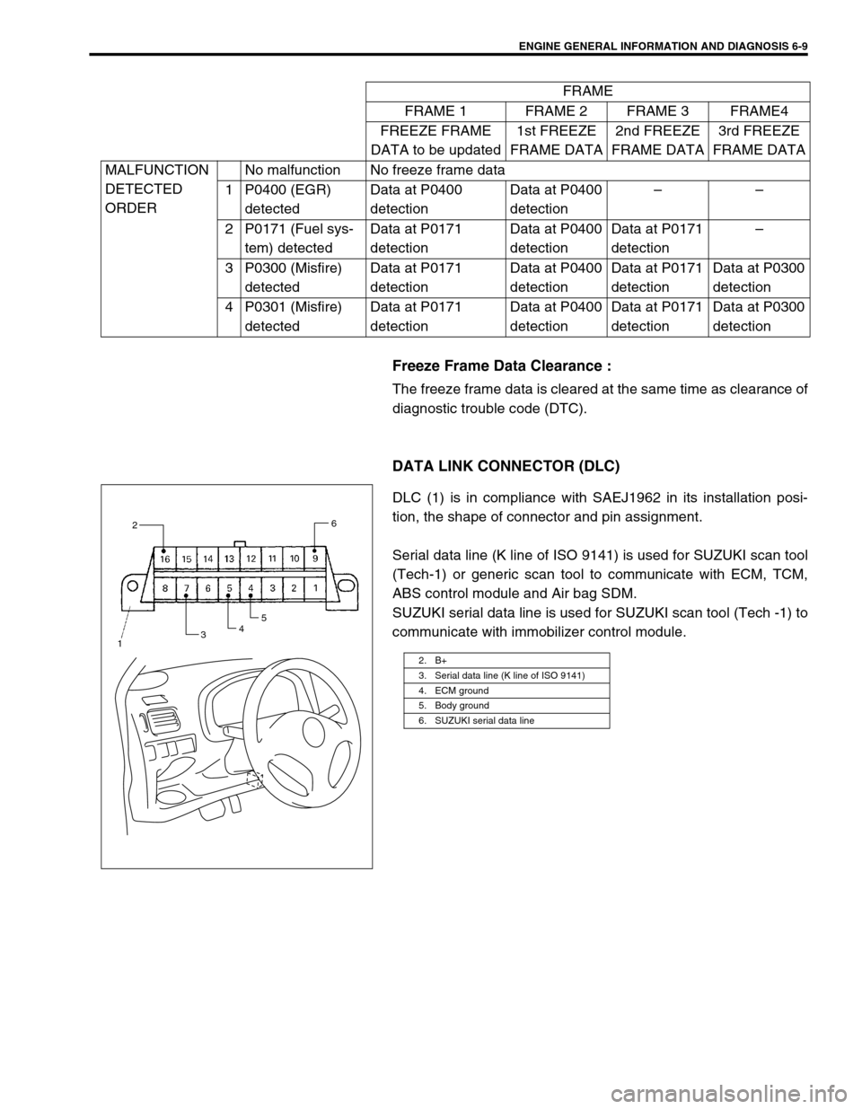
DLC (1) is in compliance with SAEJ1962 in its installation posi-
tion, the shape of connector and pin assignment.
Serial data line (K line of ISO 9141) is used for SUZUKI scan tool
(Tech-1) or generic scan tool to communicate with ECM, TCM,
ABS control module and Air bag SDM.
SUZUKI serial data line is used for SUZUKI scan tool (Tech -1) to
communicate with immobilizer control module.FRAME
FRAME 1 FRAME 2 FRAME 3 FRAME4
FREEZE FRAME
DATA to be updated1st FREEZE
FRAME DATA2nd FREEZE
FRAME DATA3rd FREEZE
FRAME DATA
MALFUNCTION
DETECTED
ORDERNo malfunction No freeze frame data
1 P0400 (EGR)
detectedData at P0400
detectionData at P0400
detection––
2 P0171 (Fuel sys-
tem) detectedData at P0171
detectionData at P0400
detectionData at P0171
detection–
3 P0300 (Misfire)
detectedData at P0171
detectionData at P0400
detectionData at P0171
detectionData at P0300
detection
4 P0301 (Misfire)
detectedData at P0171
detectionData at P0400
detectionData at P0171
detectionData at P0300
detection
2. B+
3. Serial data line (K line of ISO 9141)
4. ECM ground
5. Body ground
6. SUZUKI serial data line
2
3456
1
Page 380 of 698
ENGINE GENERAL INFORMATION AND DIAGNOSIS 6-11
DATA LINK CONNECTOR (DLC)
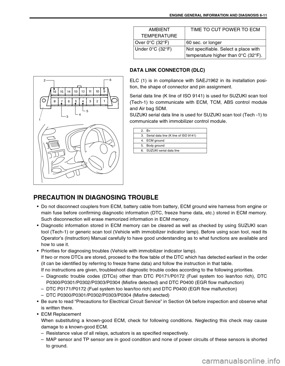
ELC (1) is in compliance with SAEJ1962 in its installation posi-
tion, the shape of connector and pin assignment.
Serial data line (K line of ISO 9141) is used for SUZUKI scan tool
(Tech-1) to communicate with ECM, TCM, ABS control module
and Air bag SDM.
SUZUKI serial data line is used for SUZUKI scan tool (Tech -1) to
communicate with immobilizer control module.
PRECAUTION IN DIAGNOSING TROUBLE
Do not disconnect couplers from ECM, battery cable from battery, ECM ground wire harness from engine or
main fuse before confirming diagnostic information (DTC, freeze frame data, etc.) stored in ECM memory.
Such disconnection will erase memorized information in ECM memory.
Diagnostic information stored in ECM memory can be cleared as well as checked by using SUZUKI scan
tool (Tech-1) or generic scan tool (Vehicle with immobilizer indicator lamp). Before using scan tool, read its
Operator’s (Instruction) Manual carefully to have good understanding as to what functions are available and
how to use it.
Priorities for diagnosing troubles (Vehicle with immobilizer indicator lamp).
If two or more DTCs are stored, proceed to the flow table of the DTC which has detected earliest in the order
(it can be identified by referring to freeze frame data) and follow the instruction in that table.
If no instructions are given, troubleshoot diagnostic trouble codes according to the following priorities.
–Diagnostic trouble codes (DTCs) other than DTC P0171/P0172 (Fuel system too lean/too rich), DTC
P0300/P0301/P0302/P0303/P0304 (Misfire detected) and DTC P0400 (EGR flow malfunction)
–DTC P0171/P0172 (Fuel system too lean/too rich) and DTC P0400 (EGR flow malfunction)
–DTC P0300/P0301/P0302/P0303/P0304 (Misfire detected)
Be sure to read “Precautions for Electrical Circuit Service” in Section 0A before inspection and observe what
is written there.
ECM Replacement
When substituting a known-good ECM, check for following conditions. Neglecting this check may cause
damage to a known-good ECM.
–Resistance value of all relays, actuators is as specified respectively.
–MAP sensor and TP sensor are in good condition and none of power circuits of these sensors is shorted
to ground.AMBIENT
TEMPERATURETIME TO CUT POWER TO ECM
Over 0°C (32°F) 60 sec. or longer
Under 0°C (32°F) Not specifiable. Select a place with
temperature higher than 0°C (32°F).
2. B+
3. Serial data line (K line of ISO 9141)
4. ECM ground
5. Body ground
6. SUZUKI serial data line
2
3456
1
Page 386 of 698
ENGINE GENERAL INFORMATION AND DIAGNOSIS 6-17
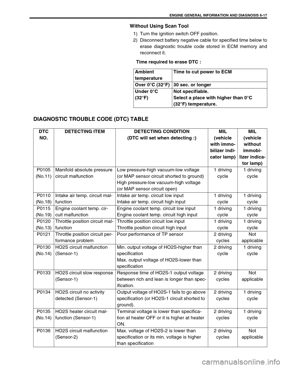
Without Using Scan Tool
1) Turn the ignition switch OFF position.
2) Disconnect battery negative cable for specified time below to
erase diagnostic trouble code stored in ECM memory and
reconnect it.
Time required to erase DTC :
DIAGNOSTIC TROUBLE CODE (DTC) TABLE
Ambient
temperatureTime to cut power to ECM
Over 0°C (32°F) 30 sec. or longer
Under 0°C
(32°F)Not specifiable.
Select a place with higher than 0°C
(32°F) temperature.
DTC
NO.DETECTING ITEM DETECTING CONDITION
(DTC will set when detecting :)MIL
(vehicle
with immo-
bilizer indi-
cator lamp)MIL
(vehicle
without
immobi-
lizer indica-
tor lamp)
P0105
(No.11)Manifold absolute pressure
circuit malfunctionLow pressure-high vacuum-low voltage
(or MAP sensor circuit shorted to ground)
High pressure-low vacuum-high voltage
(or MAP sensor circuit open)1 driving
cycle1 driving
cycle
P0110
(No.18)Intake air temp. circuit mal-
functionIntake air temp. circuit low input
Intake air temp. circuit high input1 driving
cycle1 driving
cycle
P0115
(No.19)Engine coolant temp. cir-
cuit malfunctionEngine coolant temp. circuit low input
Engine coolant temp. circuit high input1 driving
cycle1 driving
cycle
P0120
(No.13)Throttle position circuit mal-
functionThrottle position circuit low input
Throttle position circuit high input1 driving
cycle1 driving
cycle
P0121 Throttle position circuit per-
formance problemPoor performance of TP sensor 2 driving
cyclesNot
applicable
P0130
(No.14)HO2S circuit malfunction
(Sensor-1)Min. output voltage of HO2S-higher than
specification
Max. output voltage of HO2S-lower than
specification2 driving
cycle1 driving
cycle
P0133 HO2S circuit slow response
(Sensor-1)Response time of HO2S-1 output voltage
between rich and lean is longer than spec-
ification.2 driving
cyclesNot
applicable
P0134 HO2S circuit no activity
detected (Sensor-1)Output voltage of HO2S-1 fails to go above
specification (or HO2S-1 circuit shorted to
ground).2 driving
cycles1 driving
cycle
P0135
(No.14)HO2S heater circuit mal-
function (Sensor-1)Terminal voltage is lower than specifica-
tion at heater OFF or it is higher at heater
ON.2 driving
cycles1 driving
cycle
P0136 HO2S circuit malfunction
(Sensor-2)Max. voltage of HO2S-2 is lower than
specification or its min. voltage is higher
than specification2 driving
cyclesNot
applicable
Page 388 of 698
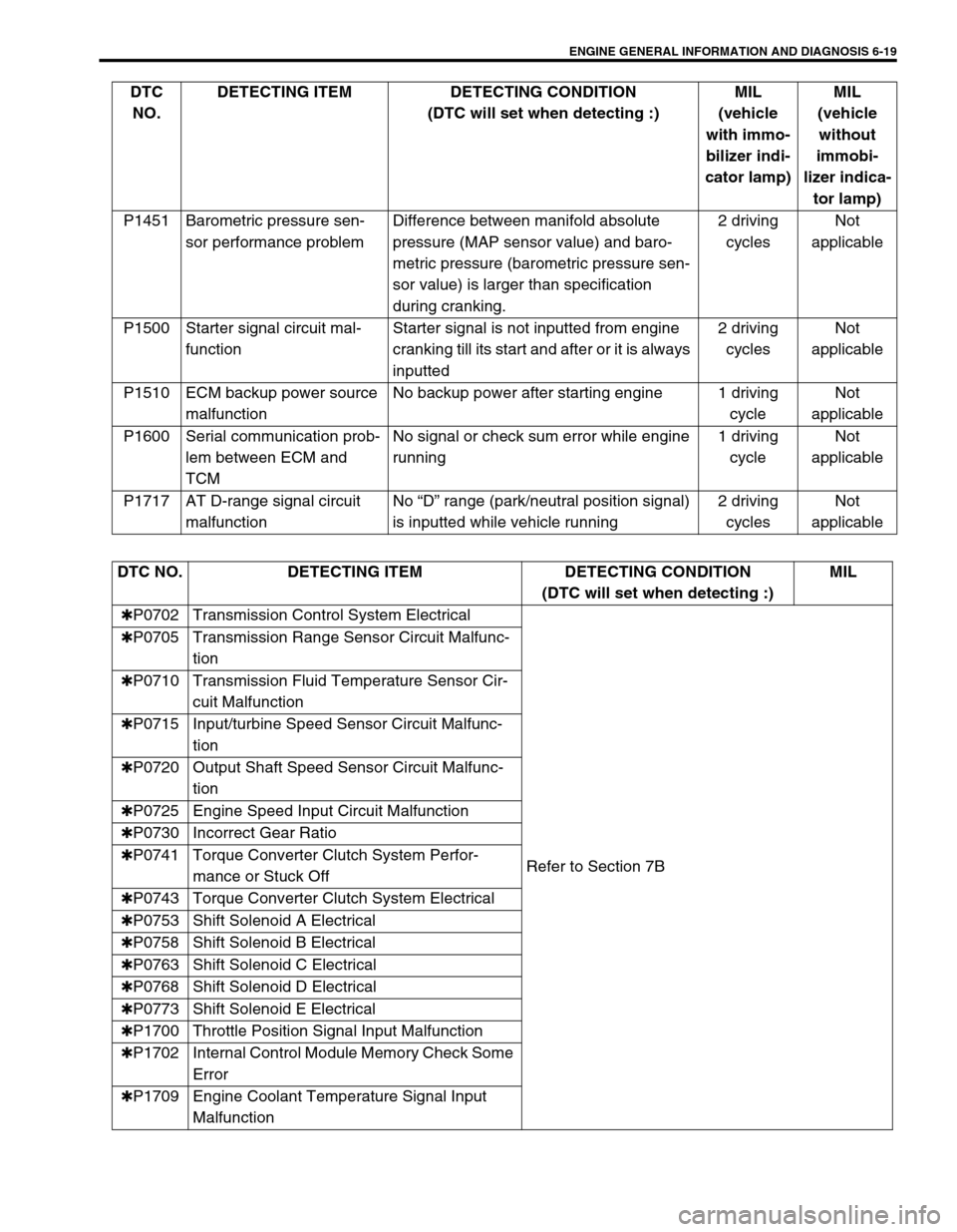
ENGINE GENERAL INFORMATION AND DIAGNOSIS 6-19
P1451 Barometric pressure sen-
sor performance problemDifference between manifold absolute
pressure (MAP sensor value) and baro-
metric pressure (barometric pressure sen-
sor value) is larger than specification
during cranking.2 driving
cyclesNot
applicable
P1500 Starter signal circuit mal-
functionStarter signal is not inputted from engine
cranking till its start and after or it is always
inputted2 driving
cyclesNot
applicable
P1510 ECM backup power source
malfunctionNo backup power after starting engine 1 driving
cycleNot
applicable
P1600 Serial communication prob-
lem between ECM and
TCMNo signal or check sum error while engine
running1 driving
cycleNot
applicable
P1717 AT D-range signal circuit
malfunctionNo “D” range (park/neutral position signal)
is inputted while vehicle running2 driving
cyclesNot
applicable DTC
NO.DETECTING ITEM DETECTING CONDITION
(DTC will set when detecting :)MIL
(vehicle
with immo-
bilizer indi-
cator lamp)MIL
(vehicle
without
immobi-
lizer indica-
tor lamp)
DTC NO. DETECTING ITEM DETECTING CONDITION
(DTC will set when detecting :)MIL
✱P0702 Transmission Control System Electrical
Refer to Section 7B ✱P0705 Transmission Range Sensor Circuit Malfunc-
tion
✱P0710 Transmission Fluid Temperature Sensor Cir-
cuit Malfunction
✱P0715 Input/turbine Speed Sensor Circuit Malfunc-
tion
✱P0720 Output Shaft Speed Sensor Circuit Malfunc-
tion
✱P0725 Engine Speed Input Circuit Malfunction
✱P0730 Incorrect Gear Ratio
✱P0741 Torque Converter Clutch System Perfor-
mance or Stuck Off
✱P0743 Torque Converter Clutch System Electrical
✱P0753 Shift Solenoid A Electrical
✱P0758 Shift Solenoid B Electrical
✱P0763 Shift Solenoid C Electrical
✱P0768 Shift Solenoid D Electrical
✱P0773 Shift Solenoid E Electrical
✱P1700 Throttle Position Signal Input Malfunction
✱P1702 Internal Control Module Memory Check Some
Error
✱P1709 Engine Coolant Temperature Signal Input
Malfunction
Page 399 of 698
6-30 ENGINE GENERAL INFORMATION AND DIAGNOSIS
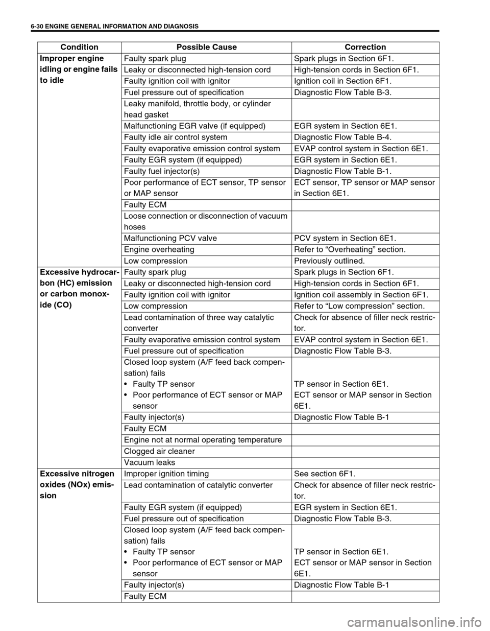
Improper engine
idling or engine fails
to idleFaulty spark plug Spark plugs in Section 6F1.
Leaky or disconnected high-tension cord High-tension cords in Section 6F1.
Faulty ignition coil with ignitor Ignition coil in Section 6F1.
Fuel pressure out of specification Diagnostic Flow Table B-3.
Leaky manifold, throttle body, or cylinder
head gasket
Malfunctioning EGR valve (if equipped) EGR system in Section 6E1.
Faulty idle air control system Diagnostic Flow Table B-4.
Faulty evaporative emission control system EVAP control system in Section 6E1.
Faulty EGR system (if equipped) EGR system in Section 6E1.
Faulty fuel injector(s) Diagnostic Flow Table B-1.
Poor performance of ECT sensor, TP sensor
or MAP sensorECT sensor, TP sensor or MAP sensor
in Section 6E1.
Faulty ECM
Loose connection or disconnection of vacuum
hoses
Malfunctioning PCV valve PCV system in Section 6E1.
Engine overheating Refer to “Overheating” section.
Low compression Previously outlined.
Excessive hydrocar-
bon (HC) emission
or carbon monox-
ide (CO)Faulty spark plug Spark plugs in Section 6F1.
Leaky or disconnected high-tension cord High-tension cords in Section 6F1.
Faulty ignition coil with ignitor Ignition coil assembly in Section 6F1.
Low compression Refer to “Low compression” section.
Lead contamination of three way catalytic
converterCheck for absence of filler neck restric-
tor.
Faulty evaporative emission control system EVAP control system in Section 6E1.
Fuel pressure out of specification Diagnostic Flow Table B-3.
Closed loop system (A/F feed back compen-
sation) fails
Faulty TP sensor
Poor performance of ECT sensor or MAP
sensorTP sensor in Section 6E1.
ECT sensor or MAP sensor in Section
6E1.
Faulty injector(s) Diagnostic Flow Table B-1
Faulty ECM
Engine not at normal operating temperature
Clogged air cleaner
Vacuum leaks
Excessive nitrogen
oxides (NOx) emis-
sionImproper ignition timing See section 6F1.
Lead contamination of catalytic converter Check for absence of filler neck restric-
tor.
Faulty EGR system (if equipped) EGR system in Section 6E1.
Fuel pressure out of specification Diagnostic Flow Table B-3.
Closed loop system (A/F feed back compen-
sation) fails
Faulty TP sensor
Poor performance of ECT sensor or MAP
sensorTP sensor in Section 6E1.
ECT sensor or MAP sensor in Section
6E1.
Faulty injector(s) Diagnostic Flow Table B-1
Faulty ECM Condition Possible Cause Correction
Page 400 of 698
ENGINE GENERAL INFORMATION AND DIAGNOSIS 6-31
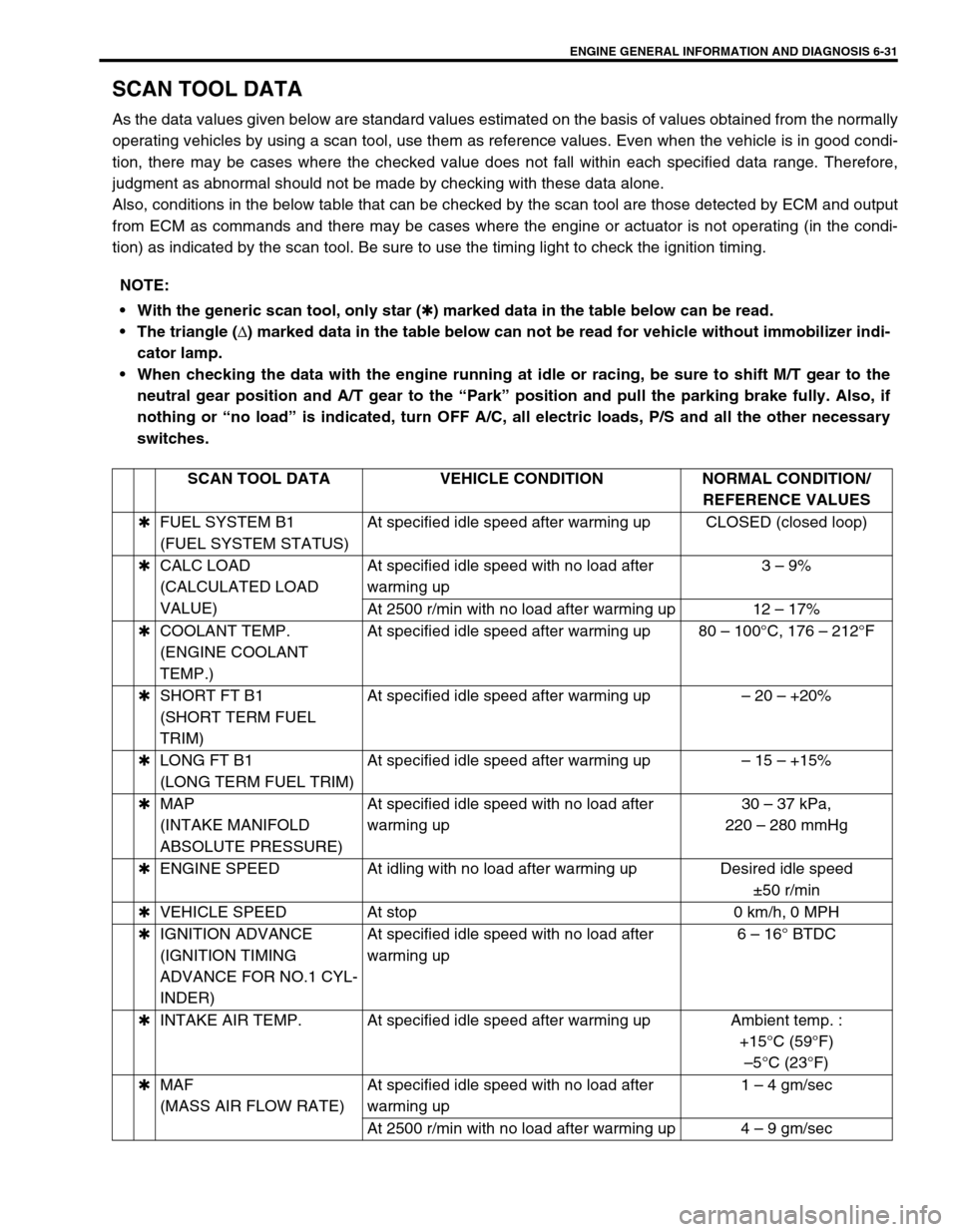
SCAN TOOL DATA
As the data values given below are standard values estimated on the basis of values obtained from the normally
operating vehicles by using a scan tool, use them as reference values. Even when the vehicle is in good condi-
tion, there may be cases where the checked value does not fall within each specified data range. Therefore,
judgment as abnormal should not be made by checking with these data alone.
Also, conditions in the below table that can be checked by the scan tool are those detected by ECM and output
from ECM as commands and there may be cases where the engine or actuator is not operating (in the condi-
tion) as indicated by the scan tool. Be sure to use the timing light to check the ignition timing.
NOTE:
With the generic scan tool, only star (
✱) marked data in the table below can be read.
The triangle (
∆) marked data in the table below can not be read for vehicle without immobilizer indi-
cator lamp.
When checking the data with the engine running at idle or racing, be sure to shift M/T gear to the
neutral gear position and A/T gear to the “Park” position and pull the parking brake fully. Also, if
nothing or “no load” is indicated, turn OFF A/C, all electric loads, P/S and all the other necessary
switches.
SCAN TOOL DATA VEHICLE CONDITION NORMAL CONDITION/
REFERENCE VALUES
✱FUEL SYSTEM B1
(FUEL SYSTEM STATUS)At specified idle speed after warming up CLOSED (closed loop)
✱CALC LOAD
(CALCULATED LOAD
VALUE)At specified idle speed with no load after
warming up3 – 9%
At 2500 r/min with no load after warming up 12 – 17%
✱COOLANT TEMP.
(ENGINE COOLANT
TEMP.)At specified idle speed after warming up 80 – 100°C, 176 – 212°F
✱SHORT FT B1
(SHORT TERM FUEL
TRIM)At specified idle speed after warming up– 20 – +20%
✱LONG FT B1
(LONG TERM FUEL TRIM)At specified idle speed after warming up– 15 – +15%
✱MAP
(INTAKE MANIFOLD
ABSOLUTE PRESSURE)At specified idle speed with no load after
warming up30 – 37 kPa,
220 – 280 mmHg
✱ENGINE SPEED At idling with no load after warming up Desired idle speed
±50 r/min
✱VEHICLE SPEED At stop 0 km/h, 0 MPH
✱IGNITION ADVANCE
(IGNITION TIMING
ADVANCE FOR NO.1 CYL-
INDER)At specified idle speed with no load after
warming up6 – 16° BTDC
✱INTAKE AIR TEMP. At specified idle speed after warming up Ambient temp. :
+15°C (59°F)
–5°C (23°F)
✱MAF
(MASS AIR FLOW RATE)At specified idle speed with no load after
warming up1 – 4 gm/sec
At 2500 r/min with no load after warming up 4 – 9 gm/sec
Page 401 of 698
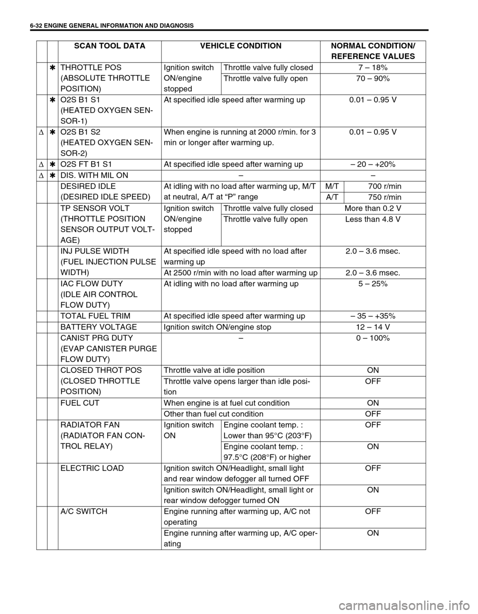
6-32 ENGINE GENERAL INFORMATION AND DIAGNOSIS
✱THROTTLE POS
(ABSOLUTE THROTTLE
POSITION)Ignition switch
ON/engine
stoppedThrottle valve fully closed 7 – 18%
Throttle valve fully open 70 – 90%
✱O2S B1 S1
(HEATED OXYGEN SEN-
SOR-1)At specified idle speed after warming up 0.01 – 0.95 V
∆✱O2S B1 S2
(HEATED OXYGEN SEN-
SOR-2)When engine is running at 2000 r/min. for 3
min or longer after warming up.0.01 – 0.95 V
∆✱O2S FT B1 S1 At specified idle speed after warning up– 20 – +20%
∆✱DIS. WITH MIL ON––
DESIRED IDLE
(DESIRED IDLE SPEED)At idling with no load after warming up, M/T
at neutral, A/T at “P” rangeM/T 700 r/min
A/T 750 r/min
TP SENSOR VOLT
(THROTTLE POSITION
SENSOR OUTPUT VOLT-
AGE)Ignition switch
ON/engine
stoppedThrottle valve fully closed More than 0.2 V
Throttle valve fully open Less than 4.8 V
INJ PULSE WIDTH
(FUEL INJECTION PULSE
WIDTH)At specified idle speed with no load after
warming up2.0 – 3.6 msec.
At 2500 r/min with no load after warming up 2.0 – 3.6 msec.
IAC FLOW DUTY
(IDLE AIR CONTROL
FLOW DUTY)At idling with no load after warming up 5 – 25%
TOTAL FUEL TRIM At specified idle speed after warming up– 35 – +35%
BATTERY VOLTAGE Ignition switch ON/engine stop 12 – 14 V
CANIST PRG DUTY
(EVAP CANISTER PURGE
FLOW DUTY)–0 – 100%
CLOSED THROT POS
(CLOSED THROTTLE
POSITION)Throttle valve at idle position ON
Throttle valve opens larger than idle posi-
tionOFF
FUEL CUT When engine is at fuel cut condition ON
Other than fuel cut condition OFF
RADIATOR FAN
(RADIATOR FAN CON-
TROL RELAY)Ignition switch
ONEngine coolant temp. :
Lower than 95°C (203°F)OFF
Engine coolant temp. :
97.5°C (208°F) or higherON
ELECTRIC LOAD Ignition switch ON/Headlight, small light
and rear window defogger all turned OFFOFF
Ignition switch ON/Headlight, small light or
rear window defogger turned ONON
A/C SWITCH Engine running after warming up, A/C not
operatingOFF
Engine running after warming up, A/C oper-
atingON SCAN TOOL DATA VEHICLE CONDITION NORMAL CONDITION/
REFERENCE VALUES