Ecm SUZUKI SWIFT 2000 1.G RG413 Service Owners Manual
[x] Cancel search | Manufacturer: SUZUKI, Model Year: 2000, Model line: SWIFT, Model: SUZUKI SWIFT 2000 1.GPages: 698, PDF Size: 16.01 MB
Page 479 of 698
6-110 ENGINE GENERAL INFORMATION AND DIAGNOSIS
DTC P1500 ENGINE STARTER SIGNAL CIRCUIT MALFUNCTION
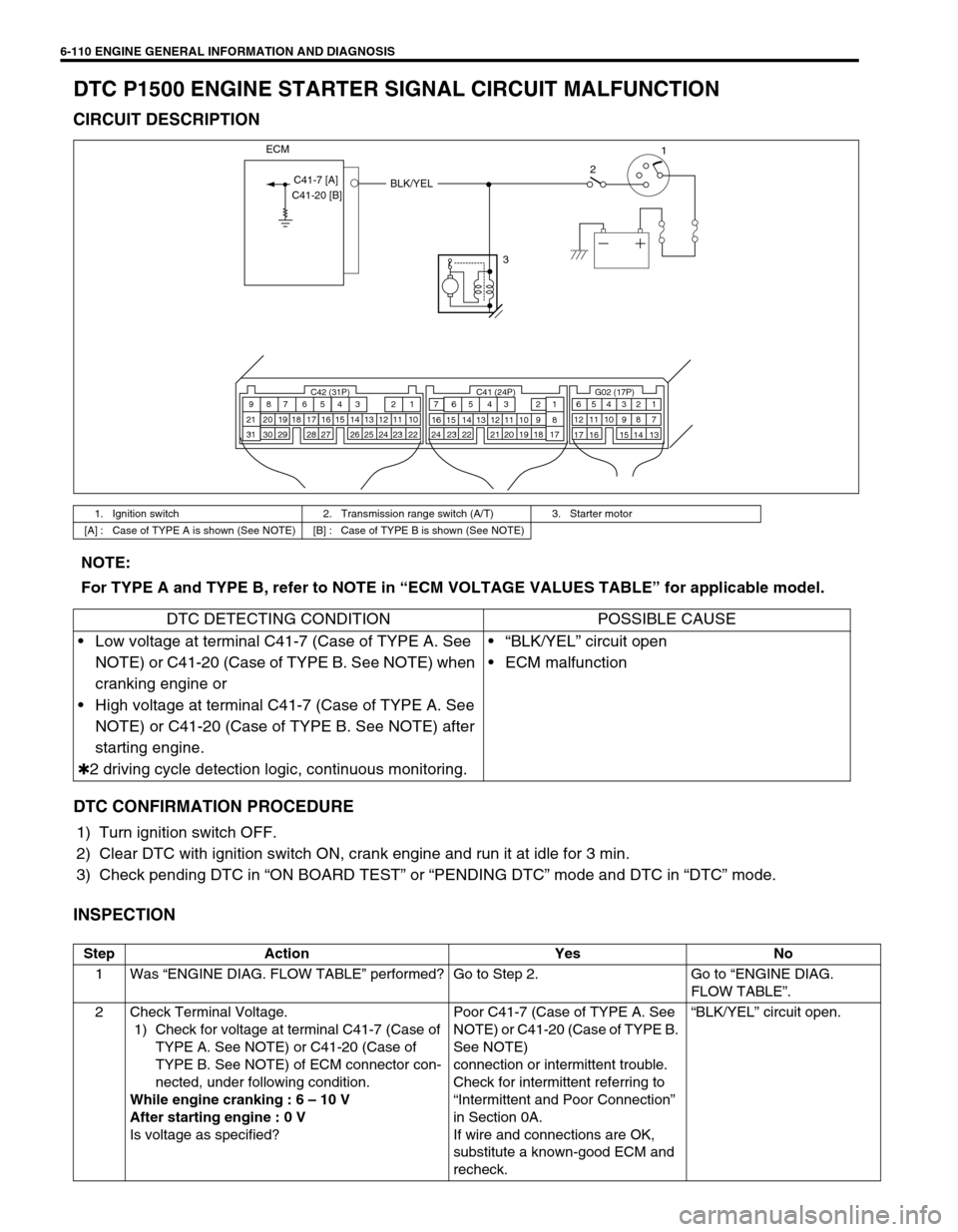
CIRCUIT DESCRIPTION
DTC CONFIRMATION PROCEDURE
1) Turn ignition switch OFF.
2) Clear DTC with ignition switch ON, crank engine and run it at idle for 3 min.
3) Check pending DTC in “ON BOARD TEST” or “PENDING DTC” mode and DTC in “DTC” mode.
INSPECTION
1. Ignition switch 2. Transmission range switch (A/T) 3. Starter motor
[A] : Case of TYPE A is shown (See NOTE) [B] : Case of TYPE B is shown (See NOTE)
321
BLK/YEL
C42 (31P) C41 (24P) G02 (17P)1 2 3 4 5 6 7 8 9
10 11 12 13 14 15 16 17 18 19 20 21
22 23 24 25 26 28 27 29 30 315 6
1 2 3 4 5 6 7
11 12
9 10 11 13 12 14 15 16
16 171 2
7 8
13 14 3 4
9 10
15 17 188
19 20 21 22 23 24
ECM
C41-7 [A]
C41-20 [B]
NOTE:
For TYPE A and TYPE B, refer to NOTE in “ECM VOLTAGE VALUES TABLE” for applicable model.
DTC DETECTING CONDITION POSSIBLE CAUSE
Low voltage at terminal C41-7 (Case of TYPE A. See
NOTE) or C41-20 (Case of TYPE B. See NOTE) when
cranking engine or
High voltage at terminal C41-7 (Case of TYPE A. See
NOTE) or C41-20 (Case of TYPE B. See NOTE) after
starting engine.
✱2 driving cycle detection logic, continuous monitoring.“BLK/YEL” circuit open
ECM malfunction
Step Action Yes No
1Was “ENGINE DIAG. FLOW TABLE” performed? Go to Step 2. Go to “ENGINE DIAG.
FLOW TABLE”.
2 Check Terminal Voltage.
1) Check for voltage at terminal C41-7 (Case of
TYPE A. See NOTE) or C41-20 (Case of
TYPE B. See NOTE) of ECM connector con-
nected, under following condition.
While engine cranking : 6 – 10 V
After starting engine : 0 V
Is voltage as specified?Poor C41-7 (Case of TYPE A. See
NOTE) or C41-20 (Case of TYPE B.
See NOTE)
connection or intermittent trouble.
Check for intermittent referring to
“Intermittent and Poor Connection”
in Section 0A.
If wire and connections are OK,
substitute a known-good ECM and
recheck.“BLK/YEL” circuit open.
Page 480 of 698
ENGINE GENERAL INFORMATION AND DIAGNOSIS 6-111
DTC P1510 ECM BACK-UP POWER SUPPLY MALFUNCTION
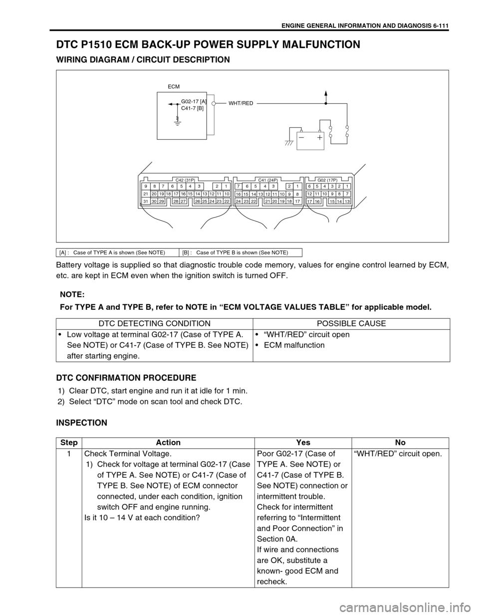
WIRING DIAGRAM / CIRCUIT DESCRIPTION
Battery voltage is supplied so that diagnostic trouble code memory, values for engine control learned by ECM,
etc. are kept in ECM even when the ignition switch is turned OFF.
DTC CONFIRMATION PROCEDURE
1) Clear DTC, start engine and run it at idle for 1 min.
2) Select “DTC” mode on scan tool and check DTC.
INSPECTION
[A] : Case of TYPE A is shown (See NOTE) [B] : Case of TYPE B is shown (See NOTE)
WHT/RED
C42 (31P) C41 (24P) G02 (17P)1 2 3 4 5 6 7 8 9
10 11 12 13 14 15 16 17 18 19 20 21
22 23 24 25 26 28 27 29 30 315 6
1 2 3 4 5 6 7
11 12
9 10 11 13 12 14 15 16
16 171 2
7 8
13 14 3 4
9 10
15 17 188
19 20 21 22 23 24
ECM
G02-17 [A]C41-7 [B]
NOTE:
For TYPE A and TYPE B, refer to NOTE in “ECM VOLTAGE VALUES TABLE” for applicable model.
DTC DETECTING CONDITION POSSIBLE CAUSE
Low voltage at terminal G02-17 (Case of TYPE A.
See NOTE) or C41-7 (Case of TYPE B. See NOTE)
after starting engine.“WHT/RED” circuit open
ECM malfunction
Step Action Yes No
1 Check Terminal Voltage.
1) Check for voltage at terminal G02-17 (Case
of TYPE A. See NOTE) or C41-7 (Case of
TYPE B. See NOTE) of ECM connector
connected, under each condition, ignition
switch OFF and engine running.
Is it 10 – 14 V at each condition?Poor G02-17 (Case of
TYPE A. See NOTE) or
C41-7 (Case of TYPE B.
See NOTE) connection or
intermittent trouble.
Check for intermittent
referring to “Intermittent
and Poor Connection” in
Section 0A.
If wire and connections
are OK, substitute a
known- good ECM and
recheck.“WHT/RED” circuit open.
Page 481 of 698
6-112 ENGINE GENERAL INFORMATION AND DIAGNOSIS
DTC P1600 SERIAL COMMUNICATION PROBLEM BETWEEN ECM AND TCM
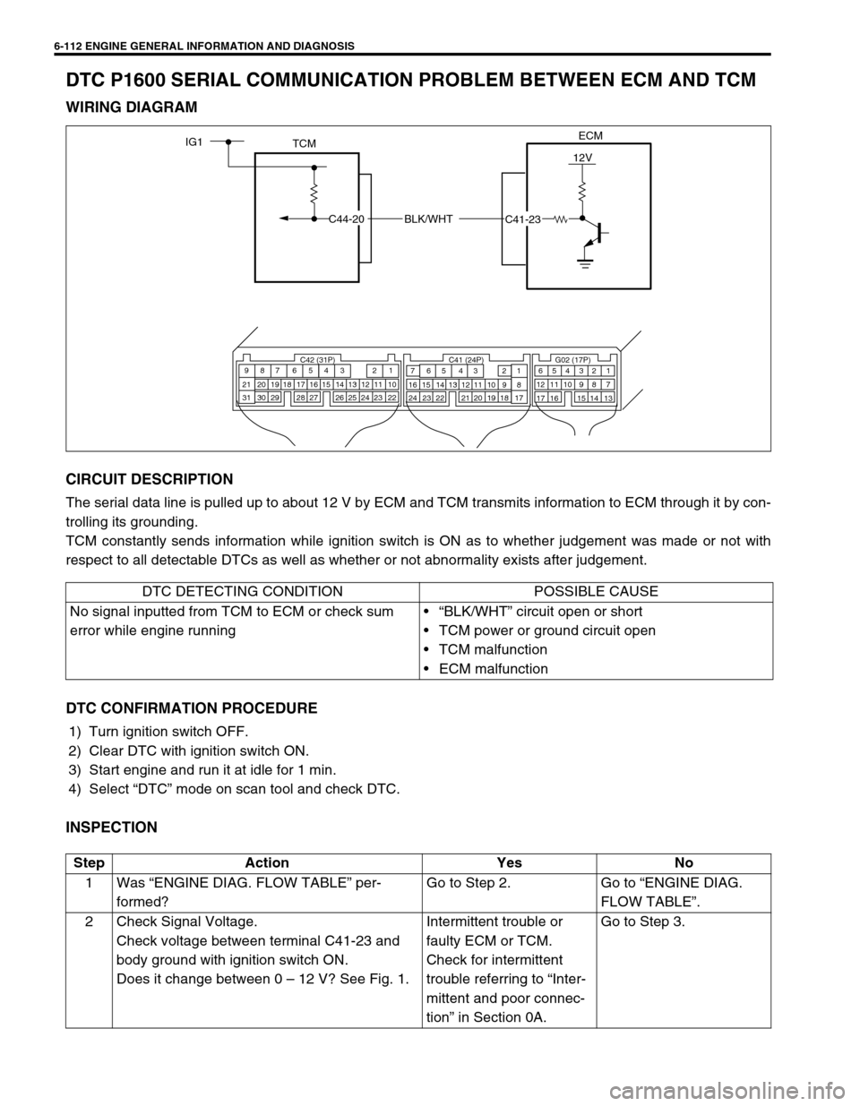
WIRING DIAGRAM
CIRCUIT DESCRIPTION
The serial data line is pulled up to about 12 V by ECM and TCM transmits information to ECM through it by con-
trolling its grounding.
TCM constantly sends information while ignition switch is ON as to whether judgement was made or not with
respect to all detectable DTCs as well as whether or not abnormality exists after judgement.
DTC CONFIRMATION PROCEDURE
1) Turn ignition switch OFF.
2) Clear DTC with ignition switch ON.
3) Start engine and run it at idle for 1 min.
4) Select “DTC” mode on scan tool and check DTC.
INSPECTION
ECM
TCMIG1
BLK/WHT
12V
C42 (31P) C41 (24P) G02 (17P)1 2 3 4 5 6 7 8 9
10 11 12 13 14 15 16 17 18 19 20 21
22 23 24 25 26 28 27 29 30 315 6
1 2 3 4 5 6 7
11 12
9 10 11 13 12 14 15 16
16 171 2
7 8
13 14 3 4
9 10
15 17 188
19 20 21 22 23 24
C44-20
C41-23
DTC DETECTING CONDITION POSSIBLE CAUSE
No signal inputted from TCM to ECM or check sum
error while engine running“BLK/WHT” circuit open or short
TCM power or ground circuit open
TCM malfunction
ECM malfunction
Step Action Yes No
1Was “ENGINE DIAG. FLOW TABLE” per-
formed?Go to Step 2. Go to “ENGINE DIAG.
FLOW TABLE”.
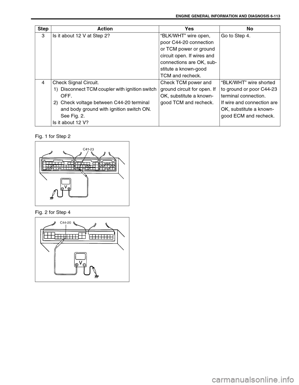
2 Check Signal Voltage.
Check voltage between terminal C41-23 and
body ground with ignition switch ON.
Does it change between 0 – 12 V? See Fig. 1.Intermittent trouble or
faulty ECM or TCM.
Check for intermittent
trouble referring to “Inter-
mittent and poor connec-
tion” in Section 0A.Go to Step 3.
Page 482 of 698
ENGINE GENERAL INFORMATION AND DIAGNOSIS 6-113
Fig. 1 for Step 2
Fig. 2 for Step 43 Is it about 12 V at Step 2?“BLK/WHT” wire open,
poor C44-20 connection
or TCM power or ground
circuit open. If wires and
connections are OK, sub-
stitute a known-good
TCM and recheck.Go to Step 4.
4 Check Signal Circuit.
1) Disconnect TCM coupler with ignition switch
OFF.
2) Check voltage between C44-20 terminal
and body ground with ignition switch ON.
See Fig. 2.
Is it about 12 V?Check TCM power and
ground circuit for open. If
OK, substitute a known-
good TCM and recheck.“BLK/WHT” wire shorted
to ground or poor C44-23
terminal connection.
If wire and connection are
OK, substitute a known-
good ECM and recheck. Step Action Yes No
Page 483 of 698
6-114 ENGINE GENERAL INFORMATION AND DIAGNOSIS
DTC P1717 A/T DRIVE RANGE (PARK/NEUTRAL POSITION) SIGNAL CIRCUIT
MALFUNCTION
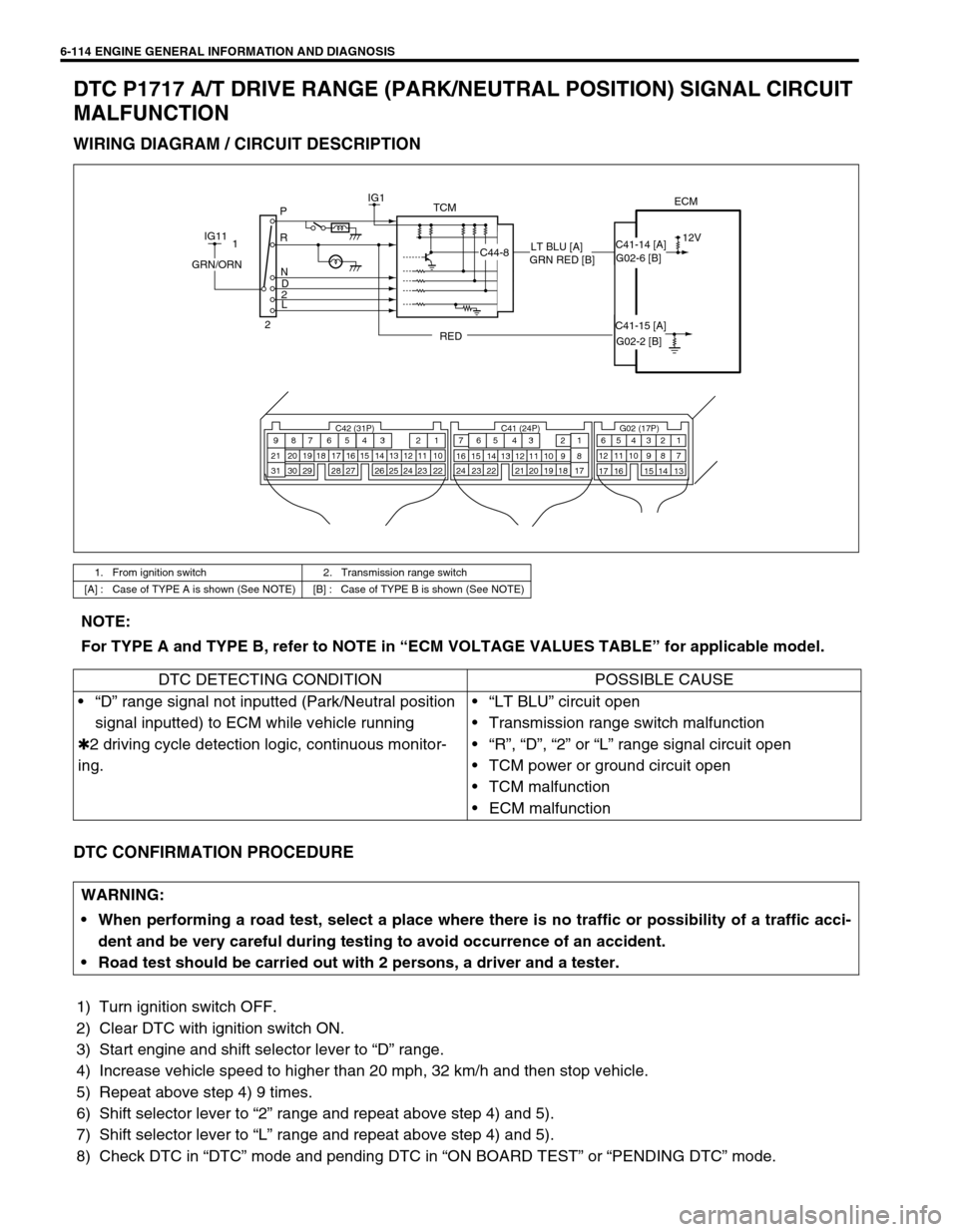
WIRING DIAGRAM / CIRCUIT DESCRIPTION
DTC CONFIRMATION PROCEDURE
1) Turn ignition switch OFF.
2) Clear DTC with ignition switch ON.
3) Start engine and shift selector lever to “D” range.
4) Increase vehicle speed to higher than 20 mph, 32 km/h and then stop vehicle.
5) Repeat above step 4) 9 times.
6) Shift selector lever to “2” range and repeat above step 4) and 5).
7) Shift selector lever to “L” range and repeat above step 4) and 5).
8) Check DTC in “DTC” mode and pending DTC in “ON BOARD TEST” or “PENDING DTC” mode.
1. From ignition switch 2. Transmission range switch
[A] : Case of TYPE A is shown (See NOTE) [B] : Case of TYPE B is shown (See NOTE)
TCMECMIG1
12V P
R
N
D
2
L
C42 (31P) C41 (24P) G02 (17P)1 2 3 4 5 6 7 8 9
10 11 12 13 14 15 16 17 18 19 20 21
22 23 24 25 26 28 27 29 30 315 6
1 2 3 4 5 6 7
11 12
9 10 11 13 12 14 15 16
16 171 2
7 8
13 14 3 4
9 10
15 17 188
19 20 21 22 23 24
IG11
C44-8
REDGRN/ORN1
2G02-6 [B] C41-14 [A]
C41-15 [A]
G02-2 [B] GRN RED [B]LT BLU [A]
NOTE:
For TYPE A and TYPE B, refer to NOTE in “ECM VOLTAGE VALUES TABLE” for applicable model.
DTC DETECTING CONDITION POSSIBLE CAUSE
“D” range signal not inputted (Park/Neutral position
signal inputted) to ECM while vehicle running
✱2 driving cycle detection logic, continuous monitor-
ing.“LT BLU” circuit open
Transmission range switch malfunction
“R”, “D”, “2” or “L” range signal circuit open
TCM power or ground circuit open
TCM malfunction
ECM malfunction
WARNING:
When performing a road test, select a place where there is no traffic or possibility of a traffic acci-
dent and be very careful during testing to avoid occurrence of an accident.
Road test should be carried out with 2 persons, a driver and a tester.
Page 484 of 698
ENGINE GENERAL INFORMATION AND DIAGNOSIS 6-115
INSPECTION
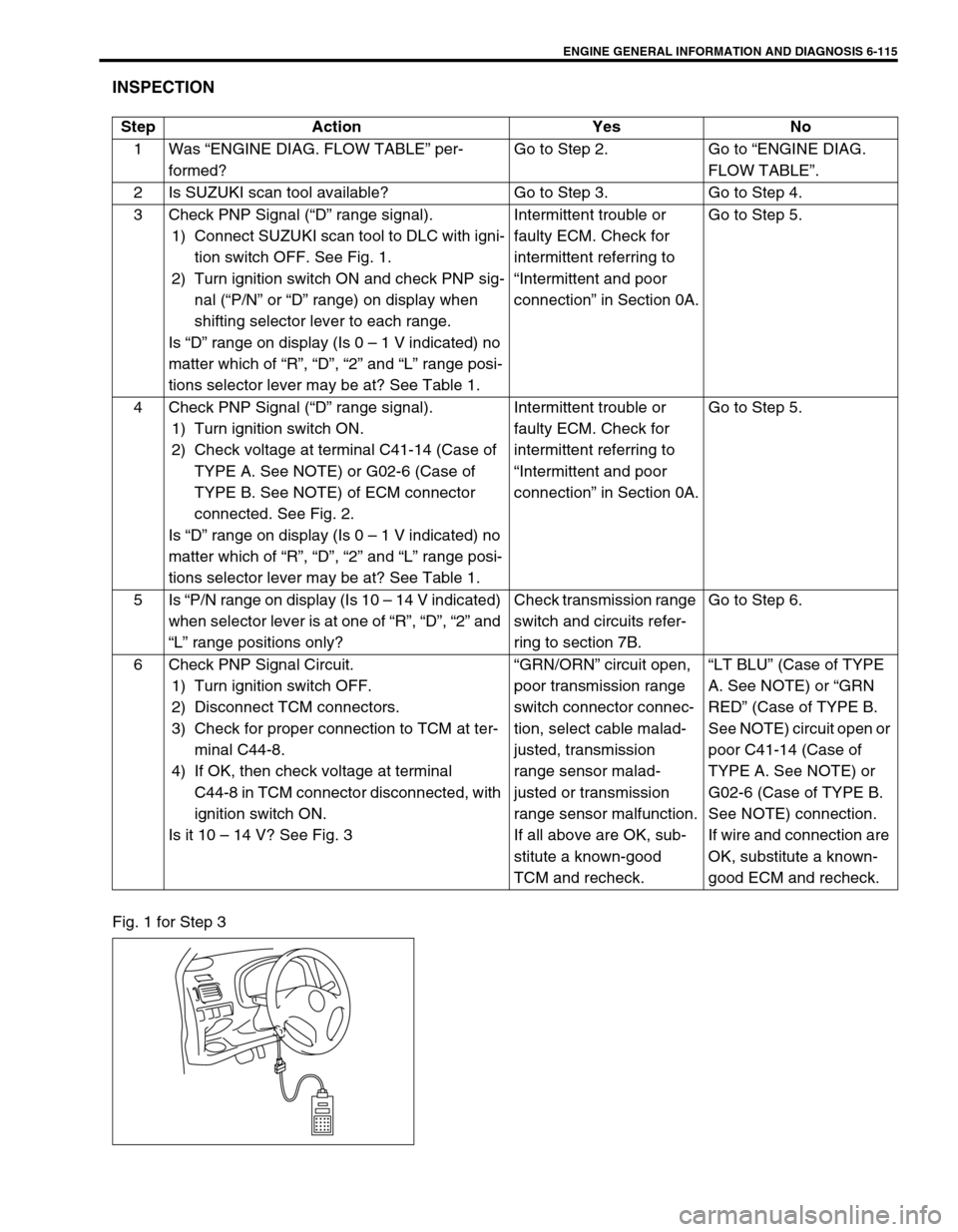
Fig. 1 for Step 3Step Action Yes No
1Was “ENGINE DIAG. FLOW TABLE” per-
formed?Go to Step 2. Go to “ENGINE DIAG.
FLOW TABLE”.
2 Is SUZUKI scan tool available? Go to Step 3. Go to Step 4.
3 Check PNP Signal (“D” range signal).
1) Connect SUZUKI scan tool to DLC with igni-
tion switch OFF. See Fig. 1.
2) Turn ignition switch ON and check PNP sig-
nal (“P/N” or “D” range) on display when
shifting selector lever to each range.
Is “D” range on display (Is 0 – 1 V indicated) no
matter which of “R”, “D”, “2” and “L” range posi-
tions selector lever may be at? See Table 1.Intermittent trouble or
faulty ECM. Check for
intermittent referring to
“Intermittent and poor
connection” in Section 0A.Go to Step 5.
4 Check PNP Signal (“D” range signal).
1) Turn ignition switch ON.
2) Check voltage at terminal C41-14 (Case of
TYPE A. See NOTE) or G02-6 (Case of
TYPE B. See NOTE) of ECM connector
connected. See Fig. 2.
Is “D” range on display (Is 0 – 1 V indicated) no
matter which of “R”, “D”, “2” and “L” range posi-
tions selector lever may be at? See Table 1.Intermittent trouble or
faulty ECM. Check for
intermittent referring to
“Intermittent and poor
connection” in Section 0A.Go to Step 5.
5Is “P/N range on display (Is 10 – 14 V indicated)
when selector lever is at one of “R”, “D”, “2” and
“L” range positions only?Check transmission range
switch and circuits refer-
ring to section 7B.Go to Step 6.
6 Check PNP Signal Circuit.
1) Turn ignition switch OFF.
2) Disconnect TCM connectors.
3) Check for proper connection to TCM at ter-
minal C44-8.
4) If OK, then check voltage at terminal
C44-8 in TCM connector disconnected, with
ignition switch ON.
Is it 10 – 14 V? See Fig. 3“GRN/ORN” circuit open,
poor transmission range
switch connector connec-
tion, select cable malad-
justed, transmission
range sensor malad-
justed or transmission
range sensor malfunction.
If all above are OK, sub-
stitute a known-good
TCM and recheck.“LT BLU” (Case of TYPE
A. See NOTE) or “GRN
RED” (Case of TYPE B.
See NOTE) circuit open or
poor C41-14 (Case of
TYPE A. See NOTE) or
G02-6 (Case of TYPE B.
See NOTE) connection.
If wire and connection are
OK, substitute a known-
good ECM and recheck.
Page 486 of 698
ENGINE GENERAL INFORMATION AND DIAGNOSIS 6-117
TABLE B-1 FUEL INJECTOR CIRCUIT CHECK
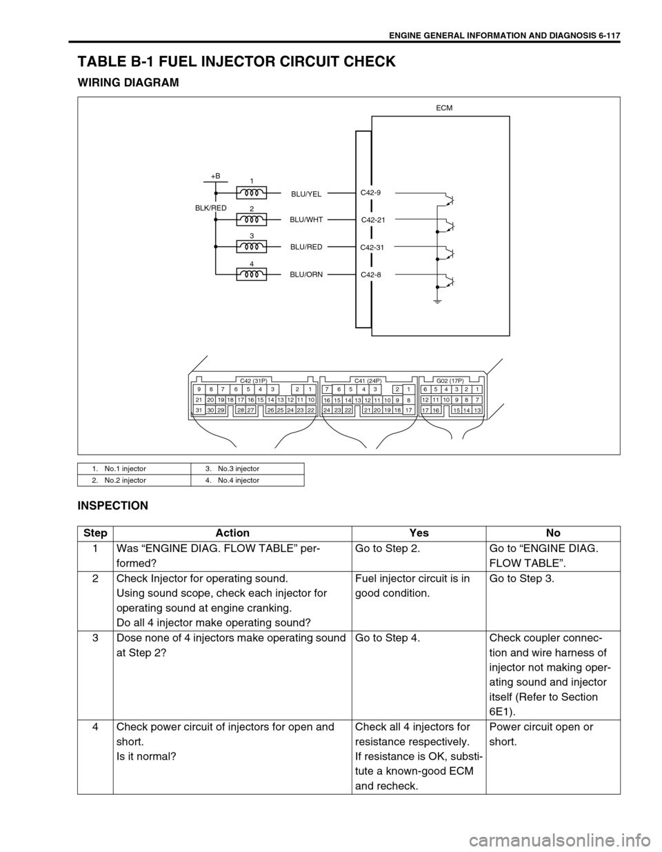
WIRING DIAGRAM
INSPECTION
1. No.1 injector 3. No.3 injector
2. No.2 injector 4. No.4 injector
ECM
1
2
3
4
+B
C42-9
C42-21
C42-8 C42-31 BLU/YEL
BLU/WHT
BLU/RED
BLU/ORN
BLK/RED
C42 (31P) C41 (24P) G02 (17P)1 2 3 4 5 6 7 8 9
10 11 12 13 14 15 16 17 18 19 20 21
22 23 24 25 26 28 27 29 30 315 6
1 2 3 4 5 6 7
11 12
9 10 11 13 12 14 15 16
16 171 2
7 8
13 14 3 4
9 10
15 17 188
19 20 21 22 23 24
Step Action Yes No
1Was “ENGINE DIAG. FLOW TABLE” per-
formed?Go to Step 2. Go to “ENGINE DIAG.
FLOW TABLE”.
2 Check Injector for operating sound.
Using sound scope, check each injector for
operating sound at engine cranking.
Do all 4 injector make operating sound?Fuel injector circuit is in
good condition.Go to Step 3.
3 Dose none of 4 injectors make operating sound
at Step 2?Go to Step 4. Check coupler connec-
tion and wire harness of
injector not making oper-
ating sound and injector
itself (Refer to Section
6E1).
4 Check power circuit of injectors for open and
short.
Is it normal?Check all 4 injectors for
resistance respectively.
If resistance is OK, substi-
tute a known-good ECM
and recheck.Power circuit open or
short.
Page 487 of 698
!"##$%&'()'&%(&'&*+,%)'-.*/+0).'%+'1%1)+('.2)2
0+3,&%3"4%-5&,%65/6%+'1%)02%7)*75)0%78&79
:)*)'(%1)+(*+/
)'26&70).'
!" #$%&'($)('*%&+, -" #$%&'($)(
+B
M
PNK
PNK
BLK BLK/WHT
BLK/RED
C41-19
ECM
C42 (31P) C41 (24P) G02 (17P)1 2 3 4 5 6 7 8 9
10 11 12 13 14 15 16 17 18 19 20 21
22 23 24 25 26 28 27 29 30 315 6
1 2 3 4 5 6 7
11 12
9 10 11 13 12 14 15 16
16 171 2
7 8
13 14 3 4
9 10
15 17 188
19 20 21 22 23 24
1
C08-3 C08-42
7+50).';
7<=>?%@A%BC?=%DEF=%@
ICBCN=%@A%&7/O%KHF=%
2@=P +>@HAG Q=D 'A
! .+/'0123421'5463"'#78.'96:71;'(%*<
=>*)%?@3>'A>'BA%('-" 3>'A>'0123421'5463"'
#78.'96:71;"
- CD%EF'#$%&'G$)('C>HA*>&'B,/A%)'=>*'>(%*+AI>H"'
B%%'#IJ"'!"
4/'=$%&'($)('D%+*?'A>'>(%*+A%'=>*'-'/%E"'+=A%*'
IJHIAI>H'/KIAED'82@#$%&'($)('EI*E$IA'I/'IH'
J>>?'E>H?IAI>H"3>'A>'BA%('L"
L CD%EF'#$%&'G$)('=>*'>(%*+AI>H"
!M N%)>O%'=$%&'($)('*%&+,'=*>)'*%&+,'P>Q'KIAD'
IJHIAI>H'/KIAED'8##"
-M CD%EF'=>*'(*>(%*'E>HH%EAI>H'A>'*%&+,'+A'%+ED'
A%*)IH+&"
LM 4='8RS'$/IHJ'/%*OIE%'KI*%S'E>HH%EA'A%*)IH+&/'
CTU
#IJ"'-"
4/'=$%&'($)('D%+*?'A>'>(%*+A%'+A'IJHIAI>H'/KIAED'
82@3>'A>'BA%('V" 0G2R;S'0:7R;'>*'0:7RW
N15;'EI*E$IA'>(%H'>*'=$%&'
($)(')+&=$HEAI>H"
Page 488 of 698
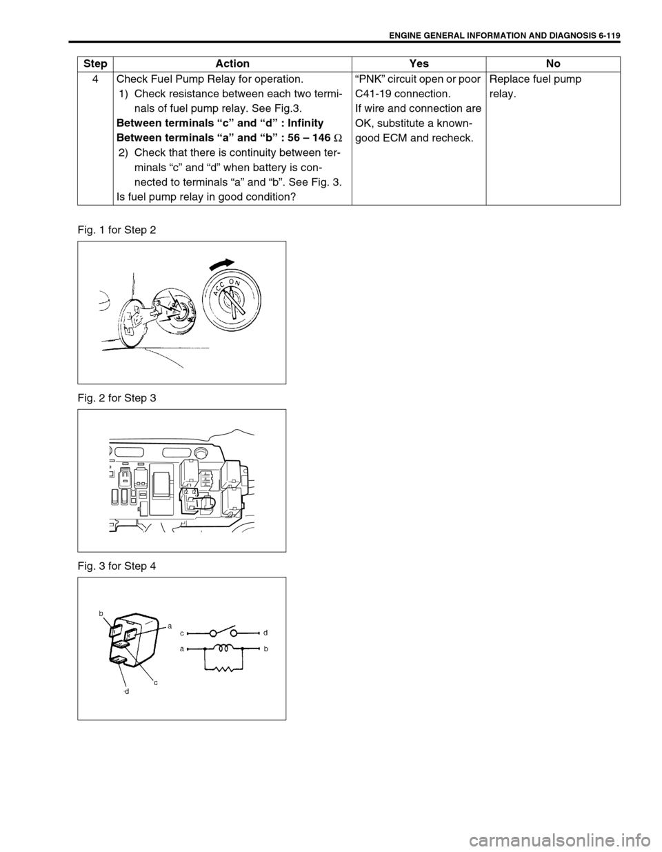
ENGINE GENERAL INFORMATION AND DIAGNOSIS 6-119
Fig. 1 for Step 2
Fig. 2 for Step 3
Fig. 3 for Step 44 Check Fuel Pump Relay for operation.
1) Check resistance between each two termi-
nals of fuel pump relay. See Fig.3.
Between terminals “c” and “d” : Infinity
Between terminals “a” and “b” : 56 – 146
Ω
2) Check that there is continuity between ter-
minals “c” and “d” when battery is con-
nected to terminals “a” and “b”. See Fig. 3.
Is fuel pump relay in good condition?“PNK” circuit open or poor
C41-19 connection.
If wire and connection are
OK, substitute a known-
good ECM and recheck.Replace fuel pump
relay. Step Action Yes No
Page 491 of 698
![SUZUKI SWIFT 2000 1.G RG413 Service Owners Manual 6-122 ENGINE GENERAL INFORMATION AND DIAGNOSIS
TABLE B-4 IDLE AIR CONTROL SYSTEM CHECK
INSPECTION
1. IAC valve 2. Main relay 3. To TCM
[A] : Case of TYPE A is shown (See NOTE) [B] : Case of TYPE B is SUZUKI SWIFT 2000 1.G RG413 Service Owners Manual 6-122 ENGINE GENERAL INFORMATION AND DIAGNOSIS
TABLE B-4 IDLE AIR CONTROL SYSTEM CHECK
INSPECTION
1. IAC valve 2. Main relay 3. To TCM
[A] : Case of TYPE A is shown (See NOTE) [B] : Case of TYPE B is](/img/20/7606/w960_7606-490.png)
6-122 ENGINE GENERAL INFORMATION AND DIAGNOSIS
TABLE B-4 IDLE AIR CONTROL SYSTEM CHECK
INSPECTION
1. IAC valve 2. Main relay 3. To TCM
[A] : Case of TYPE A is shown (See NOTE) [B] : Case of TYPE B is shown (See NOTE)
GRN/RED
BLK/YEL
BRN/WHT
BLK/RED
BLK/RED
ECM
C41-10
C41-6
C41-5
C42 (31P) C41 (24P) G02 (17P)1 2 3 4 5 6 7 8 9
10 11 12 13 14 15 16 17 18 19 20 21
22 23 24 25 26 28 27 29 30 315 6
1 2 3 4 5 6 7
11 12
9 10 11 13 12 14 15 16
16 171 2
7 8
13 14 3 4
9 10
15 17 188
19 20 21 22 23 24
3
1
2
C42-6 C41-14 [A]
G02-6 [B]
LT BLU [A]
GRN RED [B]
NOTE:
For TYPE A and TYPE B, refer to NOTE in “ECM VOLTAGE VALUES TABLE” for applicable model.
Step Action Yes No
1 Check engine idle speed and IAC duty referring
to “Idle Speed/IAC Duty Inspection” in Section
6E1.
Is idle speed within specification?Go to Step 2. Go to Step 4.
2 Is IAC duty within specification in Step 1? Go to Step 3. Check for followings :
Vacuum leak
EVAP canister purge con-
trol system
Clog of IAC air passage
Accessory engine load
Closed throttle position
(TP sensor)
Stuck of PCV valve
3 Is engine idle speed kept specified speed even
with headlight ON?System is in good condi-
tion.Check IAC system for
operation referring to Step
2 of DTC P0505 Diag.
Flow Table.
4 Was idle speed higher than specification in
Step 1?Go to Step 5. Go to Step 8.