Ecm SUZUKI SWIFT 2000 1.G RG413 Service Manual PDF
[x] Cancel search | Manufacturer: SUZUKI, Model Year: 2000, Model line: SWIFT, Model: SUZUKI SWIFT 2000 1.GPages: 698, PDF Size: 16.01 MB
Page 450 of 698
ENGINE GENERAL INFORMATION AND DIAGNOSIS 6-81
DTC P0300 RANDOM MISFIRE DETECTED (MISFIRE DETECTED AT 2 OR
MORE CYLINDERS)
DTC P0301 CYLINDER 1 MISFIRE DETECTED
DTC P0302 CYLINDER 2 MISFIRE DETECTED
DTC P0303 CYLINDER 3 MISFIRE DETECTED
DTC P0304 CYLINDER 4 MISFIRE DETECTED
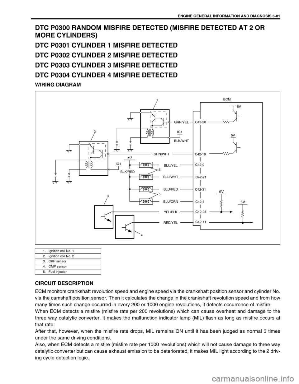
WIRING DIAGRAM
CIRCUIT DESCRIPTION
ECM monitors crankshaft revolution speed and engine speed via the crankshaft position sensor and cylinder No.
via the camshaft position sensor. Then it calculates the change in the crankshaft revolution speed and from how
many times such change occurred in every 200 or 1000 engine revolutions, it detects occurrence of misfire.
When ECM detects a misfire (misfire rate per 200 revolutions) which can cause overheat and damage to the
three way catalytic converter, it makes the malfunction indicator lamp (MIL) flash as long as misfire occurs at
that rate.
After that, however, when the misfire rate drops, MIL remains ON until it has been judged as normal 3 times
under the same driving conditions.
Also, when ECM detects a misfire (misfire rate per 1000 revolutions) which will not cause damage to three way
catalytic converter but can cause exhaust emission to be deteriorated, it makes MIL light according to the 2 driv-
ing cycle detection logic.
1. Ignition coil No. 1
2. Ignition coil No. 2
3. CKP sensor
4. CMP sensor
5. Fuel injector
C42-20
C42-19
ECM
IG1
5V
5V
GRN/YEL
BLK/WHT
GRN/WHT
IG1 2
+B
C42-9
C42-21
C42-8
C42-23 C42-31 BLU/YEL
BLU/WHT
BLU/RED
BLU/ORN
YEL/BLK
5V
C42-11
RED/YEL
5V
BLK/RED
3
45
5
1
Page 453 of 698
6-84 ENGINE GENERAL INFORMATION AND DIAGNOSIS
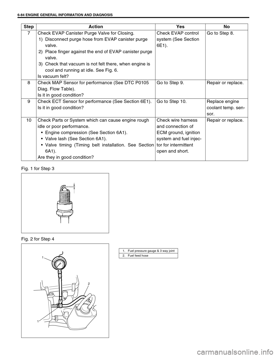
Fig. 1 for Step 3
Fig. 2 for Step 47 Check EVAP Canister Purge Valve for Closing.
1) Disconnect purge hose from EVAP canister purge
valve.
2) Place finger against the end of EVAP canister purge
valve.
3) Check that vacuum is not felt there, when engine is
cool and running at idle. See Fig. 6.
Is vacuum felt?Check EVAP control
system (See Section
6E1).Go to Step 8.
8 Check MAP Sensor for performance (See DTC P0105
Diag. Flow Table).
Is it in good condition?Go to Step 9. Repair or replace.
9 Check ECT Sensor for performance (See Section 6E1).
Is it in good condition?Go to Step 10. Replace engine
coolant temp. sen-
sor.
10 Check Parts or System which can cause engine rough
idle or poor performance.
Engine compression (See Section 6A1).
Valve lash (See Section 6A1).
Valve timing (Timing belt installation. See Section
6A1).
Are they in good condition?Check wire harness
and connection of
ECM ground, ignition
system and fuel injec-
tor for intermittent
open and short.Repair or replace. Step Action Yes No
1. Fuel pressure gauge & 3 way joint
2. Fuel feed hose
1
2
1
Page 455 of 698
6-86 ENGINE GENERAL INFORMATION AND DIAGNOSIS
DTC P0325 (DTC NO.17) KNOCK SENSOR CIRCUIT MALFUNCTION
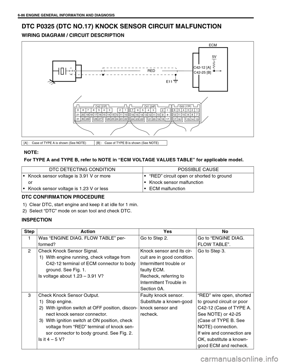
WIRING DIAGRAM / CIRCUIT DESCRIPTION
DTC CONFIRMATION PROCEDURE
1) Clear DTC, start engine and keep it at idle for 1 min.
2) Select “DTC” mode on scan tool and check DTC.
INSPECTION
[A] : Case of TYPE A is shown (See NOTE) [B] : Case of TYPE B is shown (See NOTE)
ECM
5V
RED
E11
C42 (31P) C41 (24P) G02 (17P)1 2 3 4 5 6 7 8 9
10 11 12 13 14 15 16 17 18 19 20 21
22 23 24 25 26 28 27 29 30 315 6
1 2 3 4 5 6 7
11 12
9 10 11 13 12 14 15 16
16 171 2
7 8
13 14 3 4
9 10
15 17 188
19 20 21 22 23 24
C42-12 [A]
C42-25 [B]
NOTE:
For TYPE A and TYPE B, refer to NOTE in “ECM VOLTAGE VALUES TABLE” for applicable model.
DTC DETECTING CONDITION POSSIBLE CAUSE
Knock sensor voltage is 3.91 V or more
or
Knock sensor voltage is 1.23 V or less“RED” circuit open or shorted to ground
Knock sensor malfunction
ECM malfunction
Step Action Yes No
1Was “ENGINE DIAG. FLOW TABLE” per-
formed?Go to Step 2. Go to “ENGINE DIAG.
FLOW TABLE”.
2 Check Knock Sensor Signal.
1) With engine running, check voltage from
C42-12 terminal of ECM connector to body
ground. See Fig. 1.
Is voltage about 1.23 – 3.91 V?Knock sensor and its cir-
cuit are in good condition.
Intermittent trouble or
faulty ECM.
Recheck, referring to
Intermittent Trouble in
Section 0A.Go to Step 3.
3 Check Knock Sensor Output.
1) Stop engine.
2) With ignition switch at OFF position, discon-
nect knock sensor connector.
3) With ignition switch at ON position, check
voltage from “RED” terminal of knock sen-
sor connector to body ground. See Fig. 2.
Is it 4 – 5 V?Faulty knock sensor.
Substitute a known-good
knock sensor and
recheck.“RED” wire open, shorted
to ground circuit or poor
C42-12 (Case of TYPE A.
See NOTE) or 42-25
(Case of TYPE B. See
NOTE) connection.
If wire and connection are
OK, substitute a known-
good ECM and recheck.
Page 457 of 698
6-88 ENGINE GENERAL INFORMATION AND DIAGNOSIS
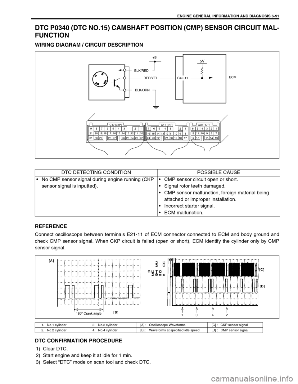
DTC P0335 (DTC NO.23) CRANKSHAFT POSITION (CKP) SENSOR CIRCUIT
MALFUNCTION
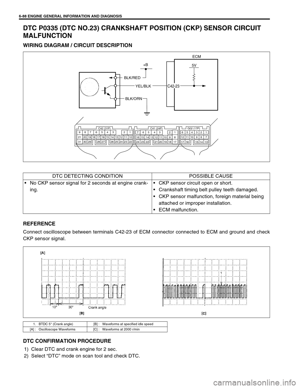
WIRING DIAGRAM / CIRCUIT DESCRIPTION
REFERENCE
Connect oscilloscope between terminals C42-23 of ECM connector connected to ECM and ground and check
CKP sensor signal.
DTC CONFIRMATION PROCEDURE
1) Clear DTC and crank engine for 2 sec.
2) Select “DTC” mode on scan tool and check DTC.
ECM
5V+B
BLK/RED
YEL/BLK
C42-23
BLK/ORN
C42 (31P) C41 (24P) G02 (17P)1 2 3 4 5 6 7 8 9
10 11 12 13 14 15 16 17 18 19 20 21
22 23 24 25 26 28 27 29 30 315 6
1 2 3 4 5 6 7
11 12
9 10 11 13 12 14 15 16
16 171 2
7 8
13 14 3 4
9 10
15 17 188
19 20 21 22 23 24
DTC DETECTING CONDITION POSSIBLE CAUSE
No CKP sensor signal for 2 seconds at engine crank-
ing.CKP sensor circuit open or short.
Crankshaft timing belt pulley teeth damaged.
CKP sensor malfunction, foreign material being
attached or improper installation.
ECM malfunction.
1. BTDC 5° (Crank angle) [B] : Waveforms at specified idle speed
[A] : Oscilloscope Waveforms [C] : Waveforms at 2000 r/min
Page 458 of 698
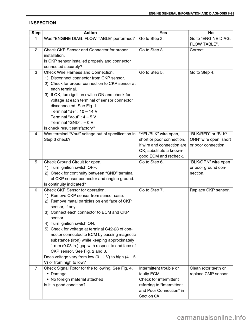
ENGINE GENERAL INFORMATION AND DIAGNOSIS 6-89
INSPECTION
Step Action Yes No
1Was “ENGINE DIAG. FLOW TABLE” performed? Go to Step 2. Go to “ENGINE DIAG.
FLOW TABLE”.
2 Check CKP Sensor and Connector for proper
installation.
Is CKP sensor installed properly and connector
connected securely?Go to Step 3. Correct.
3 Check Wire Harness and Connection.
1) Disconnect connector from CKP sensor.
2) Check for proper connection to CKP sensor at
each terminal.
3) If OK, turn ignition switch ON and check for
voltage at each terminal of sensor connector
disconnected. See Fig. 1.
Terminal “B+” : 10 – 14 V
Terminal “Vout” : 4 – 5 V
Terminal “GND” : – 0 V
Is check result satisfactory?Go to Step 5. Go to Step 4.
4 Was terminal “Vout” voltage out of specification in
Step 3 check?“YEL/BLK” wire open,
short or poor connection.
If wire and connection are
OK, substitute a known-
good ECM and recheck.“BLK/RED” or “BLK/
ORN” wire open, short
or poor connection.
5 Check Ground Circuit for open.
1) Turn ignition switch OFF.
2) Check for continuity between “GND” terminal
of CKP sensor connector and engine ground.
Is continuity indicated?Go to Step 6.“BLK/ORN” wire open
or poor ground con-
nection.
6 Check CKP Sensor for operation.
1) Remove CKP sensor from sensor case.
2) Remove metal particles on end face of CKP
sensor, if any.
3) Connect each connector to ECM and CKP
sensor.
4) Turn ignition switch ON.
5) Check for voltage at terminal C42-23 of con-
nector connected to ECM by passing magnetic
substance (iron) while keeping approximately
1 mm (0.03 in.) gap with respect to end face of
CKP sensor. See Fig. 2 and 3.
Does voltage vary from low (0 –1 V) to high (4 – 5
V) or from high to low?Go to Step 7. Replace CKP sensor.
7 Check Signal Rotor for the following. See Fig. 4.
Damage
No foreign material attached
Is it in good condition?Intermittent trouble or
faulty ECM.
Check for intermittent
referring to “Intermittent
and Poor Connection” in
Section 0A.Clean rotor teeth or
replace CMP sensor.
Page 460 of 698
ENGINE GENERAL INFORMATION AND DIAGNOSIS 6-91
DTC P0340 (DTC NO.15) CAMSHAFT POSITION (CMP) SENSOR CIRCUIT MAL-
FUNCTION
WIRING DIAGRAM / CIRCUIT DESCRIPTION
REFERENCE
Connect oscilloscope between terminals E21-11 of ECM connector connected to ECM and body ground and
check CMP sensor signal. When CKP circuit is failed (open or short), ECM identify the cylinder only by CMP
sensor signal.
DTC CONFIRMATION PROCEDURE
1) Clear DTC.
2) Start engine and keep it at idle for 1 min.
3) Select “DTC” mode on scan tool and check DTC.
ECM
5V+B
BLK/RED
RED/YEL
BLK/ORN
C42 (31P) C41 (24P) G02 (17P)1 2 3 4 5 6 7 8 9
10 11 12 13 14 15 16 17 18 19 20 21
22 23 24 25 26 28 27 29 30 315 6
1 2 3 4 5 6 7
11 12
9 10 11 13 12 14 15 16
16 171 2
7 8
13 14 3 4
9 10
15 17 188
19 20 21 22 23 24
C42-11
DTC DETECTING CONDITION POSSIBLE CAUSE
No CMP sensor signal during engine running (CKP
sensor signal is inputted).CMP sensor circuit open or short.
Signal rotor teeth damaged.
CMP sensor malfunction, foreign material being
attached or improper installation.
Incorrect starter signal.
ECM malfunction.
1. No.1 cylinder 3. No.3 cylinder [A] : Oscilloscope Waveforms [C] : CKP sensor signal
2. No.2 cylinder 4. No.4 cylinder [B] : Waveforms at specified idle speed [D] : CMP sensor signal
Page 461 of 698
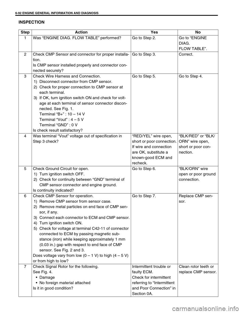
6-92 ENGINE GENERAL INFORMATION AND DIAGNOSIS
INSPECTION
Step Action Yes No
1Was “ENGINE DIAG. FLOW TABLE” performed? Go to Step 2. Go to “ENGINE
DIAG.
FLOW TABLE”.
2 Check CMP Sensor and connector for proper installa-
tion.
Is CMP sensor installed properly and connector con-
nected securely?Go to Step 3. Correct.
3 Check Wire Harness and Connection.
1) Disconnect connector from CMP sensor.
2) Check for proper connection to CMP sensor at
each terminal.
3) If OK, turn ignition switch ON and check for volt-
age at each terminal of sensor connector discon-
nected. See Fig. 1.
Terminal “B+” : 10 – 14 V
Terminal “Vout” : 4 – 5 V
Terminal “GND” : 0 V
Is check result satisfactory?Go to Step 5. Go to Step 4.
4Was terminal “Vout” voltage out of specification in
Step 3 check?“RED/YEL” wire open,
short or poor connection.
If wire and connection
are OK, substitute a
known-good ECM and
recheck.“BLK/RED” or “BLK/
ORN” wire open,
short or poor con-
nection.
5 Check Ground Circuit for open.
1) Turn ignition switch OFF.
2) Check for continuity between “GND” terminal of
CMP sensor connector and engine ground.
Is continuity indicated?Go to Step 6.“BLK/ORN” wire
open or poor ground
connection.
6 Check CMP Sensor for operation.
1) Remove CMP sensor from sensor case.
2) Remove metal particles on end face of CMP sen-
sor, if any.
3) Connect each connector to ECM and CMP sensor.
4) Turn ignition switch ON.
5) Check for voltage at terminal C42-11 of connector
connected to ECM by passing magnetic sub-
stance (iron) while keeping approximately 1 mm
(0.03 in.) gap with respect to end face of CMP
sensor. See Fig. 2 and 3.
Does voltage vary from low (0 – 1 V) to high (4 – 5 V)
or from high to low?Go to Step 7. Replace CMP sen-
sor.
7 Check Signal Rotor for the following.
See Fig. 4.
Damage
No foreign material attached
Is it in good condition?Intermittent trouble or
faulty ECM.
Check for intermittent
referring to “Intermittent
and Poor Connection” in
Section 0A.Clean rotor teeth or
replace CMP sensor.
Page 463 of 698
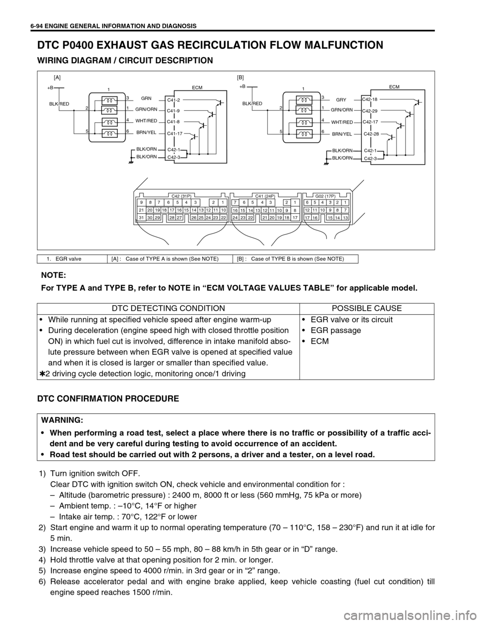
6-94 ENGINE GENERAL INFORMATION AND DIAGNOSIS
DTC P0400 EXHAUST GAS RECIRCULATION FLOW MALFUNCTION
WIRING DIAGRAM / CIRCUIT DESCRIPTION
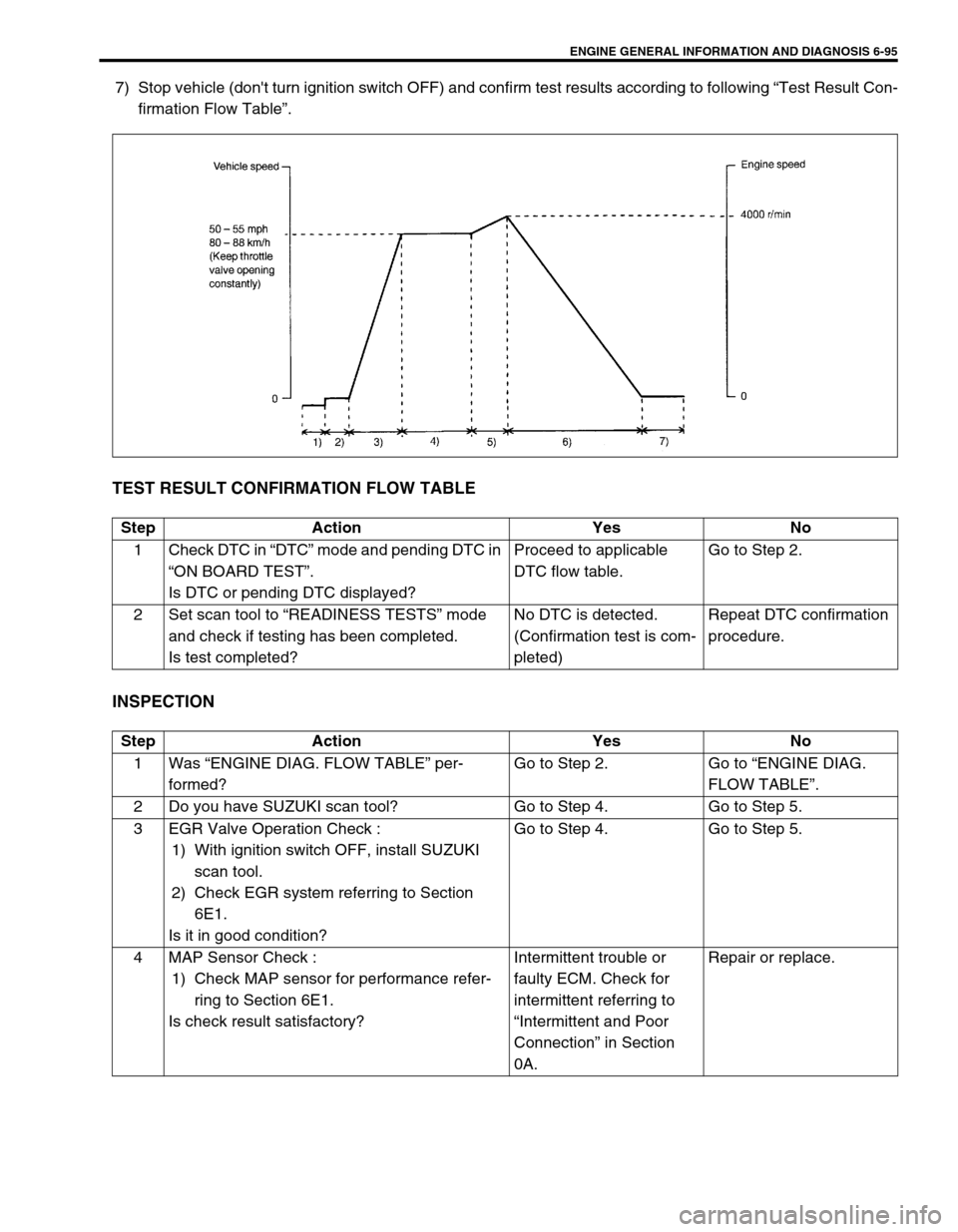
DTC CONFIRMATION PROCEDURE
1) Turn ignition switch OFF.
Clear DTC with ignition switch ON, check vehicle and environmental condition for :
–Altitude (barometric pressure) : 2400 m, 8000 ft or less (560 mmHg, 75 kPa or more)
–Ambient temp. : –10°C, 14°F or higher
–Intake air temp. : 70°C, 122°F or lower
2) Start engine and warm it up to normal operating temperature (70 – 110°C, 158 – 230°F) and run it at idle for
5 min.
3) Increase vehicle speed to 50 – 55 mph, 80 – 88 km/h in 5th gear or in “D” range.
4) Hold throttle valve at that opening position for 2 min. or longer.
5) Increase engine speed to 4000 r/min. in 3rd gear or in “2” range.
6) Release accelerator pedal and with engine brake applied, keep vehicle coasting (fuel cut condition) till
engine speed reaches 1500 r/min.
1. EGR valve [A] : Case of TYPE A is shown (See NOTE) [B] : Case of TYPE B is shown (See NOTE)
C42 (31P) C41 (24P) G02 (17P)1 2 3 4 5 6 7 8 9
10 11 12 13 14 15 16 17 18 19 20 21
22 23 24 25 26 28 27 29 30 315 6
1 2 3 4 5 6 7
11 12
9 10 11 13 12 14 15 16
16 171 2
7 8
13 14 3 4
9 10
15 17 188
19 20 21 22 23 24
+BECM
C42-18
C42-29
C42-28 C42-17
C42-1
GRY
GRN/ORN
WHT/RED
C42-3 BRN/YEL
BLK/ORN
BLK/ORN BLK/RED1
3
1 2
4
6 5
+BECM
C41-2
C41-9
C41-17 C41-8
C42-1
GRN
GRN/ORN
WHT/RED
C42-3 BRN/YEL
BLK/ORN
BLK/ORN BLK/RED1
3
1 2
4
6 5
[A][B]
NOTE:
For TYPE A and TYPE B, refer to NOTE in “ECM VOLTAGE VALUES TABLE” for applicable model.
DTC DETECTING CONDITION POSSIBLE CAUSE
While running at specified vehicle speed after engine warm-up
During deceleration (engine speed high with closed throttle position
ON) in which fuel cut is involved, difference in intake manifold abso-
lute pressure between when EGR valve is opened at specified value
and when it is closed is larger or smaller than specified value.
✱2 driving cycle detection logic, monitoring once/1 drivingEGR valve or its circuit
EGR passage
ECM
WARNING:
When performing a road test, select a place where there is no traffic or possibility of a traffic acci-
dent and be very careful during testing to avoid occurrence of an accident.
Road test should be carried out with 2 persons, a driver and a tester, on a level road.
Page 464 of 698
ENGINE GENERAL INFORMATION AND DIAGNOSIS 6-95
7) Stop vehicle (don't turn ignition switch OFF) and confirm test results according to following “Test Result Con-
firmation Flow Table”.
TEST RESULT CONFIRMATION FLOW TABLE
INSPECTION
Step Action Yes No
1Check DTC in “DTC” mode and pending DTC in
“ON BOARD TEST”.
Is DTC or pending DTC displayed?Proceed to applicable
DTC flow table.Go to Step 2.
2 Set scan tool to “READINESS TESTS” mode
and check if testing has been completed.
Is test completed?No DTC is detected.
(Confirmation test is com-
pleted)Repeat DTC confirmation
procedure.
Step Action Yes No
1Was “ENGINE DIAG. FLOW TABLE” per-
formed?Go to Step 2. Go to “ENGINE DIAG.
FLOW TABLE”.
2 Do you have SUZUKI scan tool? Go to Step 4. Go to Step 5.
3 EGR Valve Operation Check :
1) With ignition switch OFF, install SUZUKI
scan tool.
2) Check EGR system referring to Section
6E1.
Is it in good condition?Go to Step 4. Go to Step 5.
4 MAP Sensor Check :
1) Check MAP sensor for performance refer-
ring to Section 6E1.
Is check result satisfactory?Intermittent trouble or
faulty ECM. Check for
intermittent referring to
“Intermittent and Poor
Connection” in Section
0A.Repair or replace.
Page 465 of 698
6-96 ENGINE GENERAL INFORMATION AND DIAGNOSIS
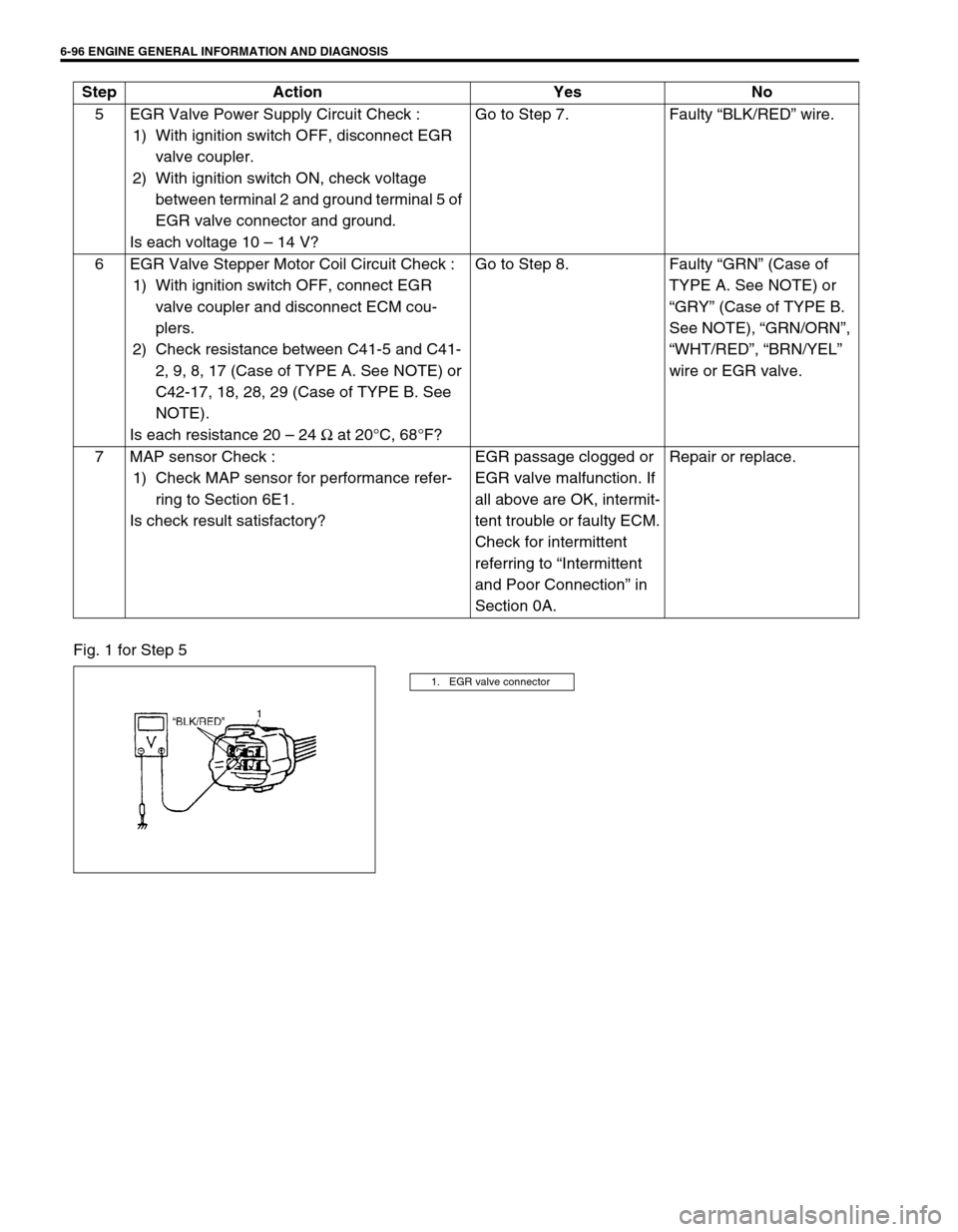
Fig. 1 for Step 55 EGR Valve Power Supply Circuit Check :
1) With ignition switch OFF, disconnect EGR
valve coupler.
2) With ignition switch ON, check voltage
between terminal 2 and ground terminal 5 of
EGR valve connector and ground.
Is each voltage 10 – 14 V?Go to Step 7. Faulty “BLK/RED” wire.
6 EGR Valve Stepper Motor Coil Circuit Check :
1) With ignition switch OFF, connect EGR
valve coupler and disconnect ECM cou-
plers.
2) Check resistance between C41-5 and C41-
2, 9, 8, 17 (Case of TYPE A. See NOTE) or
C42-17, 18, 28, 29 (Case of TYPE B. See
NOTE).
Is each resistance 20 – 24 Ω at 20°C, 68°F?Go to Step 8. Faulty “GRN” (Case of
TYPE A. See NOTE) or
“GRY” (Case of TYPE B.
See NOTE), “GRN/ORN”,
“WHT/RED”, “BRN/YEL”
wire or EGR valve.
7 MAP sensor Check :
1) Check MAP sensor for performance refer-
ring to Section 6E1.
Is check result satisfactory?EGR passage clogged or
EGR valve malfunction. If
all above are OK, intermit-
tent trouble or faulty ECM.
Check for intermittent
referring to “Intermittent
and Poor Connection” in
Section 0A.Repair or replace. Step Action Yes No
1. EGR valve connector