SUZUKI SWIFT 2000 1.G RG413 Service Workshop Manual
Manufacturer: SUZUKI, Model Year: 2000, Model line: SWIFT, Model: SUZUKI SWIFT 2000 1.GPages: 698, PDF Size: 16.01 MB
Page 101 of 698
1B-36 AIR CONDITIONING (OPTIONAL)
A/C SWITCH
REMOVAL AND INSTALLATION
Refer to “HEATER CONTROL ASSEMBLY” in Section 1A.
INSPECTION
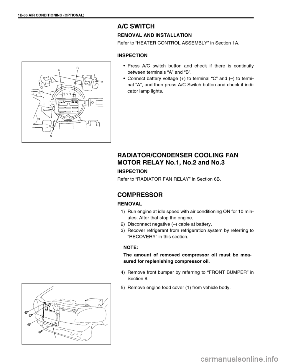
Press A/C switch button and check if there is continuity
between terminals “A” and “B”.
Connect battery voltage (+) to terminal “C” and (–) to termi-
nal “A”, and then press A/C Switch button and check if indi-
cator lamp lights.
RADIATOR/CONDENSER COOLING FAN
MOTOR RELAY No.1, No.2 and No.3
INSPECTION
Refer to “RADIATOR FAN RELAY” in Section 6B.
COMPRESSOR
REMOVAL
1) Run engine at idle speed with air conditioning ON for 10 min-
utes. After that stop the engine.
2) Disconnect negative (–) cable at battery.
3) Recover refrigerant from refrigeration system by referring to
“RECOVERY” in this section.
4) Remove front bumper by referring to “FRONT BUMPER” in
Section 8.
5) Remove engine food cover (1) from vehicle body.
NOTE:
The amount of removed compressor oil must be mea-
sured for replenishing compressor oil.
Page 102 of 698
AIR CONDITIONING (OPTIONAL) 1B-37
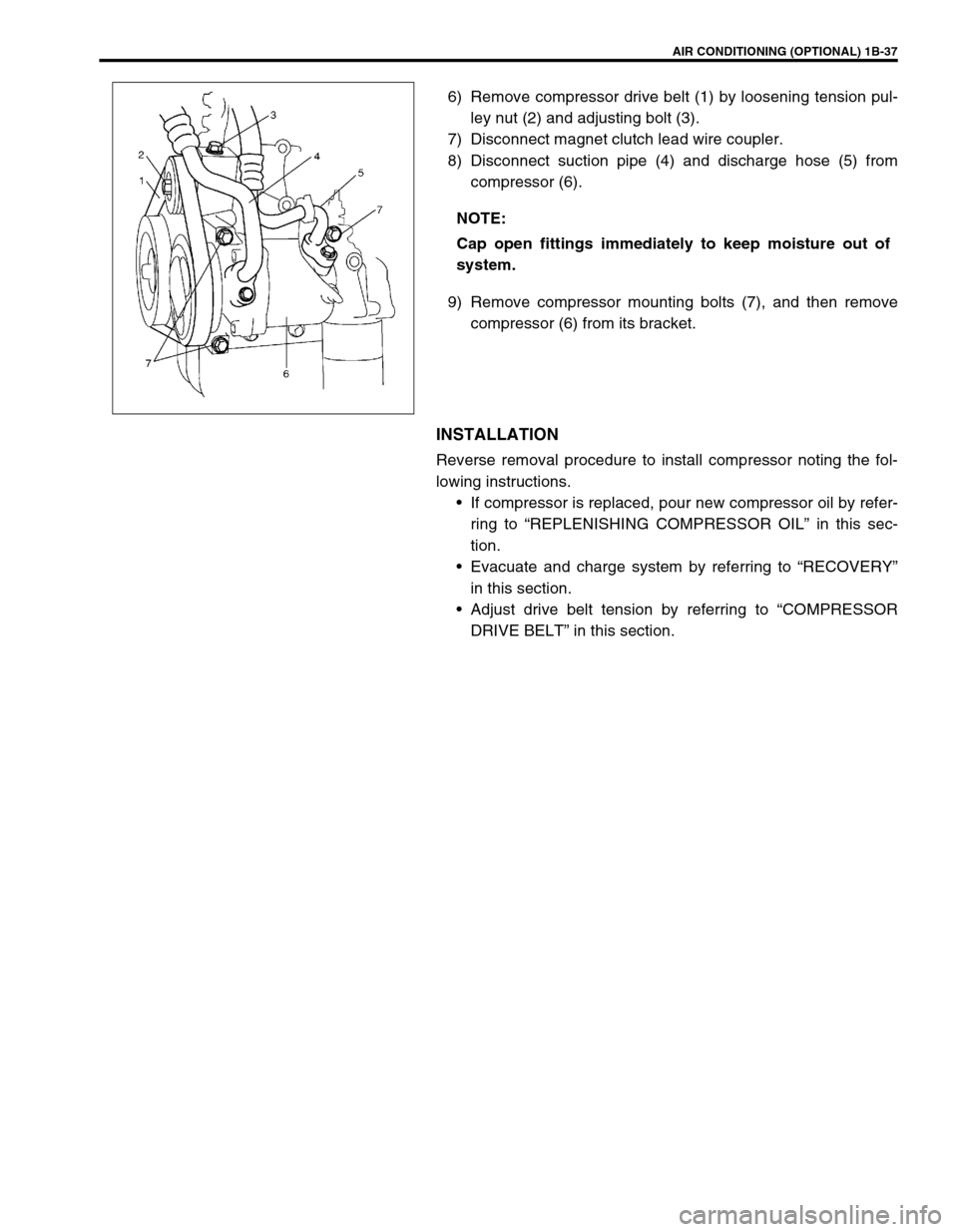
6) Remove compressor drive belt (1) by loosening tension pul-
ley nut (2) and adjusting bolt (3).
7) Disconnect magnet clutch lead wire coupler.
8) Disconnect suction pipe (4) and discharge hose (5) from
compressor (6).
9) Remove compressor mounting bolts (7), and then remove
compressor (6) from its bracket.
INSTALLATION
Reverse removal procedure to install compressor noting the fol-
lowing instructions.
If compressor is replaced, pour new compressor oil by refer-
ring to “REPLENISHING COMPRESSOR OIL” in this sec-
tion.
Evacuate and charge system by referring to “RECOVERY”
in this section.
Adjust drive belt tension by referring to “COMPRESSOR
DRIVE BELT” in this section. NOTE:
Cap open fittings immediately to keep moisture out of
system.
Page 103 of 698
1B-38 AIR CONDITIONING (OPTIONAL)
MAGNET CLUTCH
INSPECTION
Check clutch plate and clutch pulley for wear and oil soaked
conditions respectively.
Check clutch pulley bearing for noise, wear and grease leak-
age.
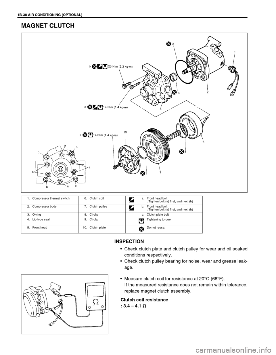
Measure clutch coil for resistance at 20°C (68°F).
If the measured resistance does not remain within tolerance,
replace magnet clutch assembly.
Clutch coil resistance
: 3.4 – 4.1
Ω
ΩΩ Ω
1. Compressor thermal switch 6. Clutch coil a. Front head bolt
: Tighten bolt (a) first, and next (b)
2. Compressor body 7. Clutch pulley b. Front head bolt
: Tighten bolt (a) first, and next (b)
3. O-ring 8. Circlip c. Clutch plate bolt
4. Lip type seal 9. Circlip Tightening torque
5. Front head 10. Clutch plate Do not reuse.
Page 104 of 698
AIR CONDITIONING (OPTIONAL) 1B-39
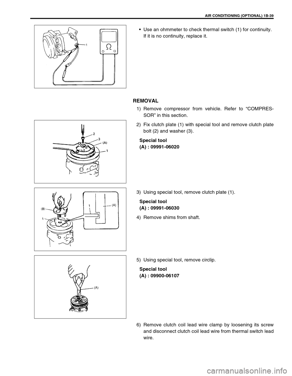
Use an ohmmeter to check thermal switch (1) for continuity.
If it is no continuity, replace it.
REMOVAL
1) Remove compressor from vehicle. Refer to “COMPRES-
SOR” in this section.
2) Fix clutch plate (1) with special tool and remove clutch plate
bolt (2) and washer (3).
Special tool
(A) : 09991-06020
3) Using special tool, remove clutch plate (1).
Special tool
(A) : 09991-06030
4) Remove shims from shaft.
5) Using special tool, remove circlip.
Special tool
(A) : 09900-06107
6) Remove clutch coil lead wire clamp by loosening its screw
and disconnect clutch coil lead wire from thermal switch lead
wire.
Page 105 of 698
1B-40 AIR CONDITIONING (OPTIONAL)
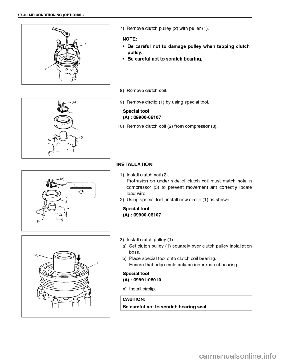
7) Remove clutch pulley (2) with puller (1).
8) Remove clutch coil.
9) Remove circlip (1) by using special tool.
Special tool
(A) : 09900-06107
10) Remove clutch coil (2) from compressor (3).
INSTALLATION
1) Install clutch coil (2).
Protrusion on under side of clutch coil must match hole in
compressor (3) to prevent movement ant correctly locate
lead wire.
2) Using special tool, install new circlip (1) as shown.
Special tool
(A) : 09900-06107
3) Install clutch pulley (1).
a) Set clutch pulley (1) squarely over clutch pulley installation
boss.
b) Place special tool onto clutch coil bearing.
Ensure that edge rests only on inner race of bearing.
Special tool
(A) : 09991-06010
c) Install circlip. NOTE:
Be careful not to damage pulley when tapping clutch
pulley.
Be careful not to scratch bearing.
CAUTION:
Be careful not to scratch bearing seal.
Page 106 of 698
AIR CONDITIONING (OPTIONAL) 1B-41
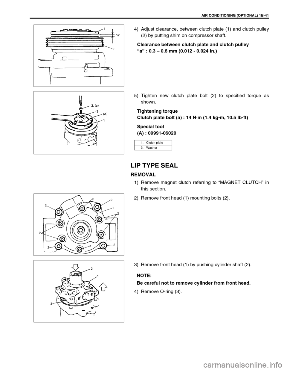
4) Adjust clearance, between clutch plate (1) and clutch pulley
(2) by putting shim on compressor shaft.
Clearance between clutch plate and clutch pulley
“a” : 0.3 – 0.6 mm (0.012 - 0.024 in.)
5) Tighten new clutch plate bolt (2) to specified torque as
shown.
Tightening torque
Clutch plate bolt (a) : 14 N·m (1.4 kg-m, 10.5 lb-ft)
Special tool
(A) : 09991-06020
LIP TYPE SEAL
REMOVAL
1) Remove magnet clutch referring to “MAGNET CLUTCH” in
this section.
2) Remove front head (1) mounting bolts (2).
3) Remove front head (1) by pushing cylinder shaft (2).
4) Remove O-ring (3).
1. Clutch plate
3. Washer
NOTE:
Be careful not to remove cylinder from front head.
Page 107 of 698
1B-42 AIR CONDITIONING (OPTIONAL)
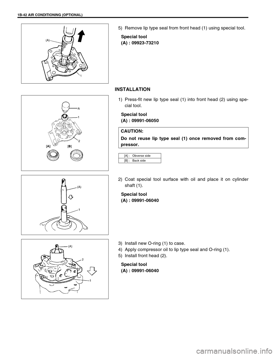
5) Remove lip type seal from front head (1) using special tool.
Special tool
(A) : 09923-73210
INSTALLATION
1) Press-fit new lip type seal (1) into front head (2) using spe-
cial tool.
Special tool
(A) : 09991-06050
2) Coat special tool surface with oil and place it on cylinder
shaft (1).
Special tool
(A) : 09991-06040
3) Install new O-ring (1) to case.
4) Apply compressor oil to lip type seal and O-ring (1).
5) Install front head (2).
Special tool
(A) : 09991-06040
CAUTION:
Do not reuse lip type seal (1) once removed from com-
pressor.
[A] : Obverse side
[B] : Back side
Page 108 of 698
AIR CONDITIONING (OPTIONAL) 1B-43
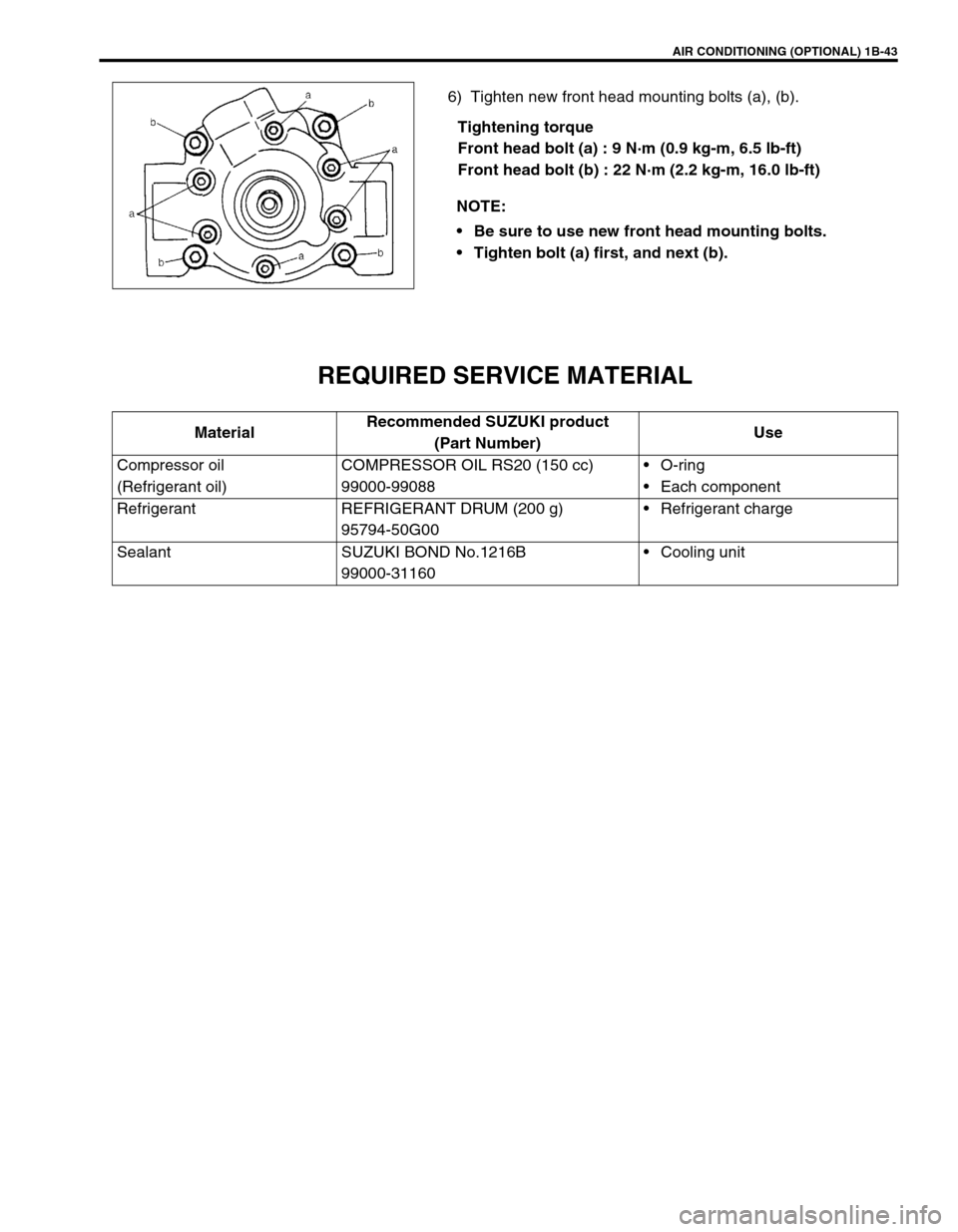
6) Tighten new front head mounting bolts (a), (b).
Tightening torque
Front head bolt (a) : 9 N·m (0.9 kg-m, 6.5 lb-ft)
Front head bolt (b) : 22 N·m (2.2 kg-m, 16.0 lb-ft)
REQUIRED SERVICE MATERIAL
NOTE:
Be sure to use new front head mounting bolts.
Tighten bolt (a) first, and next (b).
MaterialRecommended SUZUKI product
(Part Number)Use
Compressor oil
(Refrigerant oil)COMPRESSOR OIL RS20 (150 cc)
99000-99088O-ring
Each component
Refrigerant REFRIGERANT DRUM (200 g)
95794-50G00Refrigerant charge
Sealant SUZUKI BOND No.1216B
99000-31160Cooling unit
Page 109 of 698
1B-44 AIR CONDITIONING (OPTIONAL)
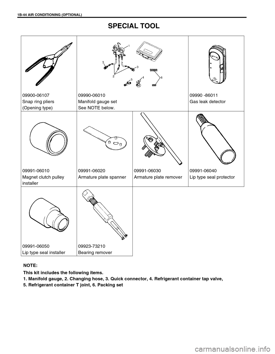
SPECIAL TOOL
09900-06107 09990-06010 09990 -86011
Snap ring pliers
(Opening type)Manifold gauge set
See NOTE below.Gas leak detector
09991-06010 09991-06020 09991-06030 09991-06040
Magnet clutch pulley
installerArmature plate spanner Armature plate remover Lip type seal protector
09991-06050 09923-73210
Lip type seal installer Bearing remover
NOTE:
This kit includes the following items.
1. Manifold gauge, 2. Changing hose, 3. Quick connector, 4. Refrigerant container tap valve,
5. Refrigerant container T joint, 6. Packing set
Page 110 of 698
STEERING, SUSPENSION, WHEELS AND TIRES 3-1
6F1
6F2
6G
6H
6K
3
7A1
7B1
7C1
7D
7E
7F
8A
8B
8C
8D
8E
9
10
10A
10B
SECTION 3
STEERING, SUSPENSION, WHEELS AND TIRES
DIAGNOSIS . . . . . . . . . . . . . . . . . . . . . . . . . . . . . . . . . . . . . . . . . . . . . . . . . . . . . . . . . . . . . . . . . 3-2
FRONT END ALIGNMENT . . . . . . . . . . . . . . . . . . . . . . . . . . . . . . . . . . . . . . . . . . . . . . . . . . . . . . Section 3A
MANUAL RACK AND PINION . . . . . . . . . . . . . . . . . . . . . . . . . . . . . . . . . . . . . . . . . . . . . . . . . . . Section 3B
ELECTRICAL POWER STEERING (P/S) SYSTEM . . . . . . . . . . . . . . . . . . . . . . . . . . . . . . . . . . Section 3B1
STEERING WHEEL AND COLUMN . . . . . . . . . . . . . . . . . . . . . . . . . . . . . . . . . . . . . . . . . . . . . . Section 3C
FRONT SUSPENSION . . . . . . . . . . . . . . . . . . . . . . . . . . . . . . . . . . . . . . . . . . . . . . . . . . . . . . . . . Section 3D
REAR SUSPENSION . . . . . . . . . . . . . . . . . . . . . . . . . . . . . . . . . . . . . . . . . . . . . . . . . . . . . . . . . . Section 3E
WHEELS AND TIRES . . . . . . . . . . . . . . . . . . . . . . . . . . . . . . . . . . . . . . . . . . . . . . . . . . . . . . . . . Section 3F
CONTENTS
DIAGNOSIS ........................................................ 3-2
GENERAL DIAGNOSIS .................................. 3-2
DIAGNOSIS TABLE ........................................ 3-2
TIRE DIAGNOSIS ........................................... 3-5
IRREGULAR AND/OR PREMATURE
WEAR.......................................................... 3-5WEAR INDICATORS .................................. 3-5
RADIAL TIRE WADDLE.............................. 3-6
RADIAL TIRE LEAD.................................... 3-7
VIBRATION DIAGNOSIS................................ 3-7