belt SUZUKI SWIFT 2000 1.G RG413 Service Owner's Manual
[x] Cancel search | Manufacturer: SUZUKI, Model Year: 2000, Model line: SWIFT, Model: SUZUKI SWIFT 2000 1.GPages: 698, PDF Size: 16.01 MB
Page 247 of 698
3F-2 WHEELS AND TIRES
GENERAL DESCRIPTION
TIRES
This vehicle is equipped with the following tire.
Tire size
: 165/70R14
The tire is of tubeless type. The tire is designed to operate satisfactorily with loads up to the full rated load
capacity when inflated to the recommended inflation pressures.
Correct tire pressures and driving habits have an important influence on tire life. Heavy cornering, excessively
rapid acceleration, and unnecessary sharp braking increase tire wear.
WHEELS
Standard equipment wheels are the following steel wheel.
Wheel size
: 14 x 4 1/2 J
REPLACEMENT TIRES
When replacement is necessary, the original equipment type tire should be used. Refer to the “Tire Placard”.
Replacement tires should be of the same size, load range and construction as those originally on the vehicle.
Use of any other size or type tire may affect ride, handling, speedometer/odometer calibration, vehicle ground
clearance and tire or snow chain clearance to the body and chassis.
It is recommended that new tires be installed in pairs on the same axle. If necessary to replace only one tire, it
should be paired with the tire having the most tread, to equalize braking traction.
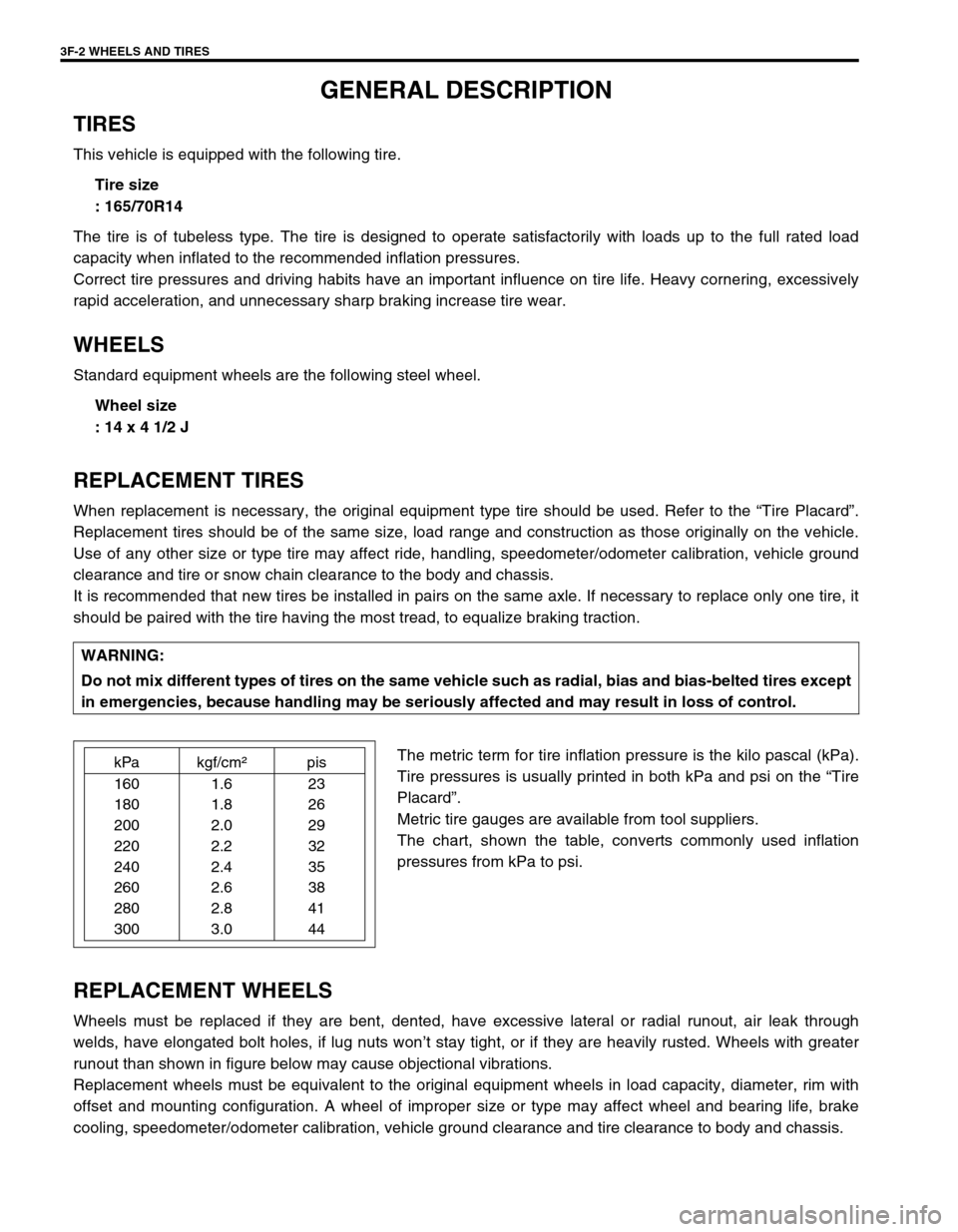
The metric term for tire inflation pressure is the kilo pascal (kPa).
Tire pressures is usually printed in both kPa and psi on the “Tire
Placard”.
Metric tire gauges are available from tool suppliers.
The chart, shown the table, converts commonly used inflation
pressures from kPa to psi.
REPLACEMENT WHEELS
Wheels must be replaced if they are bent, dented, have excessive lateral or radial runout, air leak through
welds, have elongated bolt holes, if lug nuts won’t stay tight, or if they are heavily rusted. Wheels with greater
runout than shown in figure below may cause objectional vibrations.
Replacement wheels must be equivalent to the original equipment wheels in load capacity, diameter, rim with
offset and mounting configuration. A wheel of improper size or type may affect wheel and bearing life, brake
cooling, speedometer/odometer calibration, vehicle ground clearance and tire clearance to body and chassis.WARNING:
Do not mix different types of tires on the same vehicle such as radial, bias and bias-belted tires except
in emergencies, because handling may be seriously affected and may result in loss of control.
kPa kgf/cm²pis
160 1.6 23
180 1.8 26
200 2.0 29
220 2.2 32
240 2.4 35
260 2.6 38
280 2.8 41
300 3.0 44
Page 391 of 698
6-22 ENGINE GENERAL INFORMATION AND DIAGNOSIS
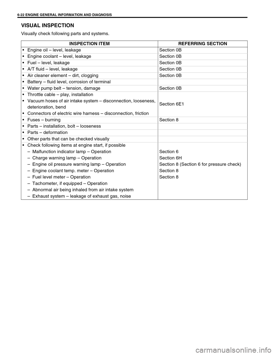
VISUAL INSPECTION
Visually check following parts and systems.
INSPECTION ITEM REFERRING SECTION
Engine oil – level, leakage Section 0B
Engine coolant – level, leakage Section 0B
Fuel – level, leakage Section 0B
A/T fluid – level, leakage Section 0B
Air cleaner element – dirt, clogging Section 0B
Battery – fluid level, corrosion of terminal
Water pump belt – tension, damage Section 0B
Throttle cable – play, installation
Section 6E1 Vacuum hoses of air intake system – disconnection, looseness,
deterioration, bend
Connectors of electric wire harness – disconnection, friction
Fuses – burning Section 8
Parts – installation, bolt – looseness
Parts – deformation
Other parts that can be checked visually
Check following items at engine start, if possible
–Malfunction indicator lamp – Operation Section 6
–Charge warning lamp – Operation Section 6H
–Engine oil pressure warning lamp – Operation Section 8 (Section 6 for pressure check)
–Engine coolant temp. meter – Operation Section 8
–Fuel level meter – Operation Section 8
–Tachometer, if equipped – Operation
–Abnormal air being inhaled from air intake system
–Exhaust system – leakage of exhaust gas, noise
Page 406 of 698
ENGINE GENERAL INFORMATION AND DIAGNOSIS 6-37
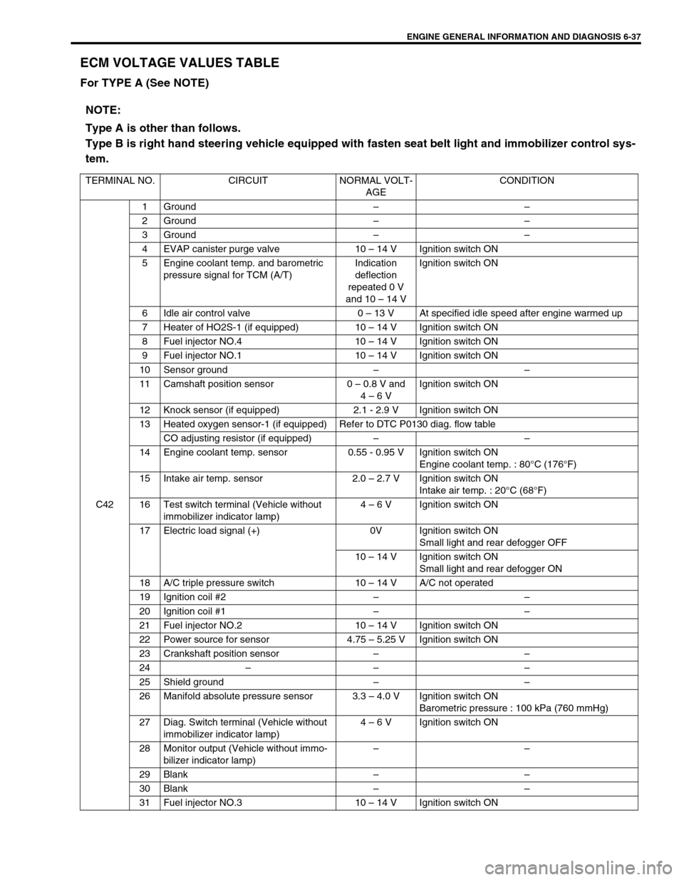
ECM VOLTAGE VALUES TABLE
For TYPE A (See NOTE)
NOTE:
Type A is other than follows.
Type B is right hand steering vehicle equipped with fasten seat belt light and immobilizer control sys-
tem.
TERMINAL NO. CIRCUIT NORMAL VOLT-
AGECONDITION
C421 Ground––
2 Ground––
3 Ground––
4 EVAP canister purge valve 10 – 14 V Ignition switch ON
5 Engine coolant temp. and barometric
pressure signal for TCM (A/T)Indication
deflection
repeated 0 V
and 10 – 14 VIgnition switch ON
6 Idle air control valve 0 – 13 V At specified idle speed after engine warmed up
7 Heater of HO2S-1 (if equipped) 10 – 14 V Ignition switch ON
8 Fuel injector NO.4 10 – 14 V Ignition switch ON
9 Fuel injector NO.1 10 – 14 V Ignition switch ON
10 Sensor ground––
11 Camshaft position sensor 0 – 0.8 V and
4 – 6 VIgnition switch ON
12 Knock sensor (if equipped) 2.1 - 2.9 V Ignition switch ON
13 Heated oxygen sensor-1 (if equipped) Refer to DTC P0130 diag. flow table
CO adjusting resistor (if equipped)––
14 Engine coolant temp. sensor 0.55 - 0.95 V Ignition switch ON
Engine coolant temp. : 80°C (176°F)
15 Intake air temp. sensor 2.0 – 2.7 V Ignition switch ON
Intake air temp. : 20°C (68°F)
16 Test switch terminal (Vehicle without
immobilizer indicator lamp)4 – 6 V Ignition switch ON
17 Electric load signal (+) 0V Ignition switch ON
Small light and rear defogger OFF
10 – 14 V Ignition switch ON
Small light and rear defogger ON
18 A/C triple pressure switch 10 – 14 V A/C not operated
19 Ignition coil #2––
20 Ignition coil #1––
21 Fuel injector NO.2 10 – 14 V Ignition switch ON
22 Power source for sensor 4.75 – 5.25 V Ignition switch ON
23 Crankshaft position sensor––
24–– –
25 Shield ground––
26 Manifold absolute pressure sensor 3.3 – 4.0 V Ignition switch ON
Barometric pressure : 100 kPa (760 mmHg)
27 Diag. Switch terminal (Vehicle without
immobilizer indicator lamp)4 – 6 V Ignition switch ON
28 Monitor output (Vehicle without immo-
bilizer indicator lamp)––
29 Blank––
30 Blank––
31 Fuel injector NO.3 10 – 14 V Ignition switch ON
Page 453 of 698
6-84 ENGINE GENERAL INFORMATION AND DIAGNOSIS
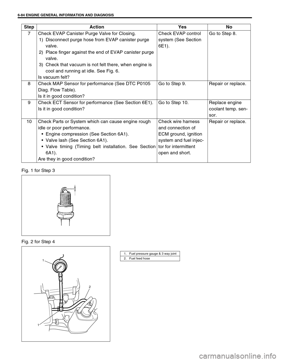
Fig. 1 for Step 3
Fig. 2 for Step 47 Check EVAP Canister Purge Valve for Closing.
1) Disconnect purge hose from EVAP canister purge
valve.
2) Place finger against the end of EVAP canister purge
valve.
3) Check that vacuum is not felt there, when engine is
cool and running at idle. See Fig. 6.
Is vacuum felt?Check EVAP control
system (See Section
6E1).Go to Step 8.
8 Check MAP Sensor for performance (See DTC P0105
Diag. Flow Table).
Is it in good condition?Go to Step 9. Repair or replace.
9 Check ECT Sensor for performance (See Section 6E1).
Is it in good condition?Go to Step 10. Replace engine
coolant temp. sen-
sor.
10 Check Parts or System which can cause engine rough
idle or poor performance.
Engine compression (See Section 6A1).
Valve lash (See Section 6A1).
Valve timing (Timing belt installation. See Section
6A1).
Are they in good condition?Check wire harness
and connection of
ECM ground, ignition
system and fuel injec-
tor for intermittent
open and short.Repair or replace. Step Action Yes No
1. Fuel pressure gauge & 3 way joint
2. Fuel feed hose
1
2
1
Page 457 of 698
6-88 ENGINE GENERAL INFORMATION AND DIAGNOSIS
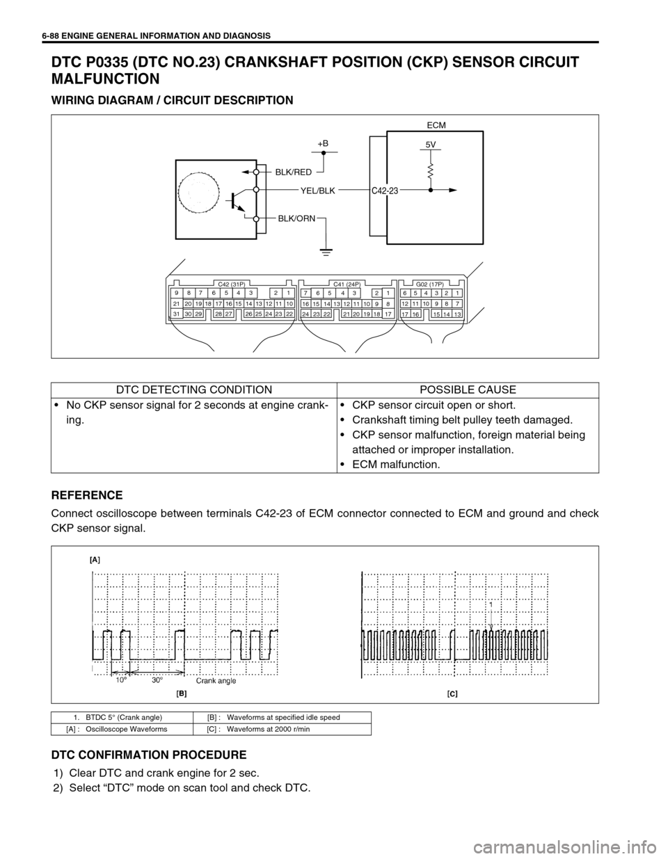
DTC P0335 (DTC NO.23) CRANKSHAFT POSITION (CKP) SENSOR CIRCUIT
MALFUNCTION
WIRING DIAGRAM / CIRCUIT DESCRIPTION
REFERENCE
Connect oscilloscope between terminals C42-23 of ECM connector connected to ECM and ground and check
CKP sensor signal.
DTC CONFIRMATION PROCEDURE
1) Clear DTC and crank engine for 2 sec.
2) Select “DTC” mode on scan tool and check DTC.
ECM
5V+B
BLK/RED
YEL/BLK
C42-23
BLK/ORN
C42 (31P) C41 (24P) G02 (17P)1 2 3 4 5 6 7 8 9
10 11 12 13 14 15 16 17 18 19 20 21
22 23 24 25 26 28 27 29 30 315 6
1 2 3 4 5 6 7
11 12
9 10 11 13 12 14 15 16
16 171 2
7 8
13 14 3 4
9 10
15 17 188
19 20 21 22 23 24
DTC DETECTING CONDITION POSSIBLE CAUSE
No CKP sensor signal for 2 seconds at engine crank-
ing.CKP sensor circuit open or short.
Crankshaft timing belt pulley teeth damaged.
CKP sensor malfunction, foreign material being
attached or improper installation.
ECM malfunction.
1. BTDC 5° (Crank angle) [B] : Waveforms at specified idle speed
[A] : Oscilloscope Waveforms [C] : Waveforms at 2000 r/min
Page 527 of 698
6A1-26 ENGINE MECHANICAL (M13 ENGINE)
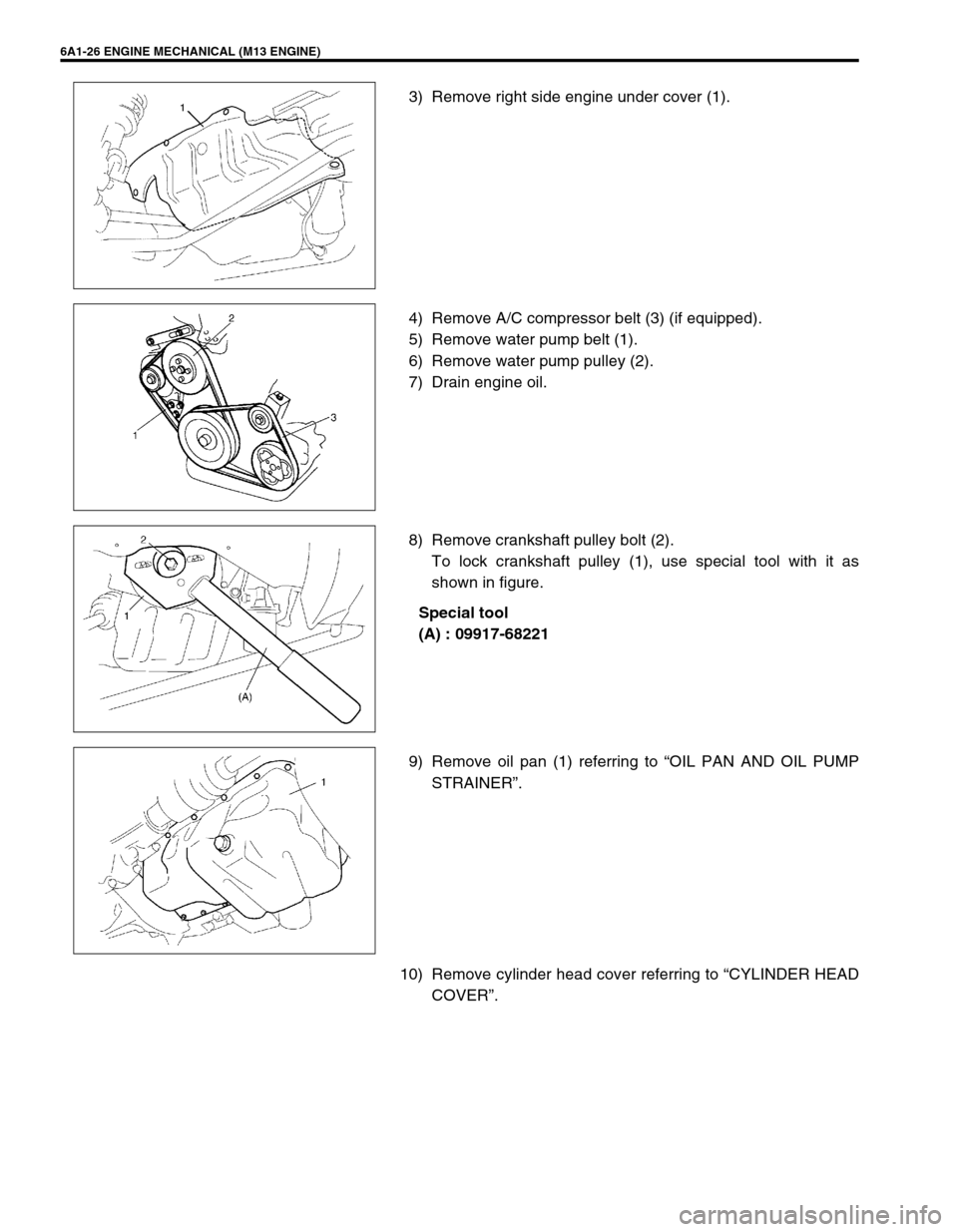
3) Remove right side engine under cover (1).
4) Remove A/C compressor belt (3) (if equipped).
5) Remove water pump belt (1).
6) Remove water pump pulley (2).
7) Drain engine oil.
8) Remove crankshaft pulley bolt (2).
To lock crankshaft pulley (1), use special tool with it as
shown in figure.
Special tool
(A) : 09917-68221
9) Remove oil pan (1) referring to “OIL PAN AND OIL PUMP
STRAINER”.
10) Remove cylinder head cover referring to “CYLINDER HEAD
COVER”.
Page 530 of 698
ENGINE MECHANICAL (M13 ENGINE) 6A1-29
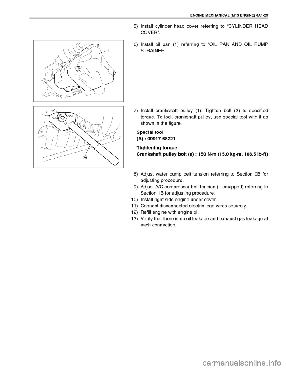
5) Install cylinder head cover referring to “CYLINDER HEAD
COVER”.
6) Install oil pan (1) referring to “OIL PAN AND OIL PUMP
STRAINER”.
7) Install crankshaft pulley (1). Tighten bolt (2) to specified
torque. To lock crankshaft pulley, use special tool with it as
shown in the figure.
Special tool
(A) : 09917-68221
Tightening torque
Crankshaft pulley bolt (a) : 150 N·m (15.0 kg-m, 108.5 lb-ft)
8) Adjust water pump belt tension referring to Section 0B for
adjusting procedure.
9) Adjust A/C compressor belt tension (if equipped) referring to
Section 1B for adjusting procedure.
10) Install right side engine under cover.
11) Connect disconnected electric lead wires securely.
12) Refill engine with engine oil.
13) Verify that there is no oil leakage and exhaust gas leakage at
each connection.
Page 539 of 698
6A1-38 ENGINE MECHANICAL (M13 ENGINE)
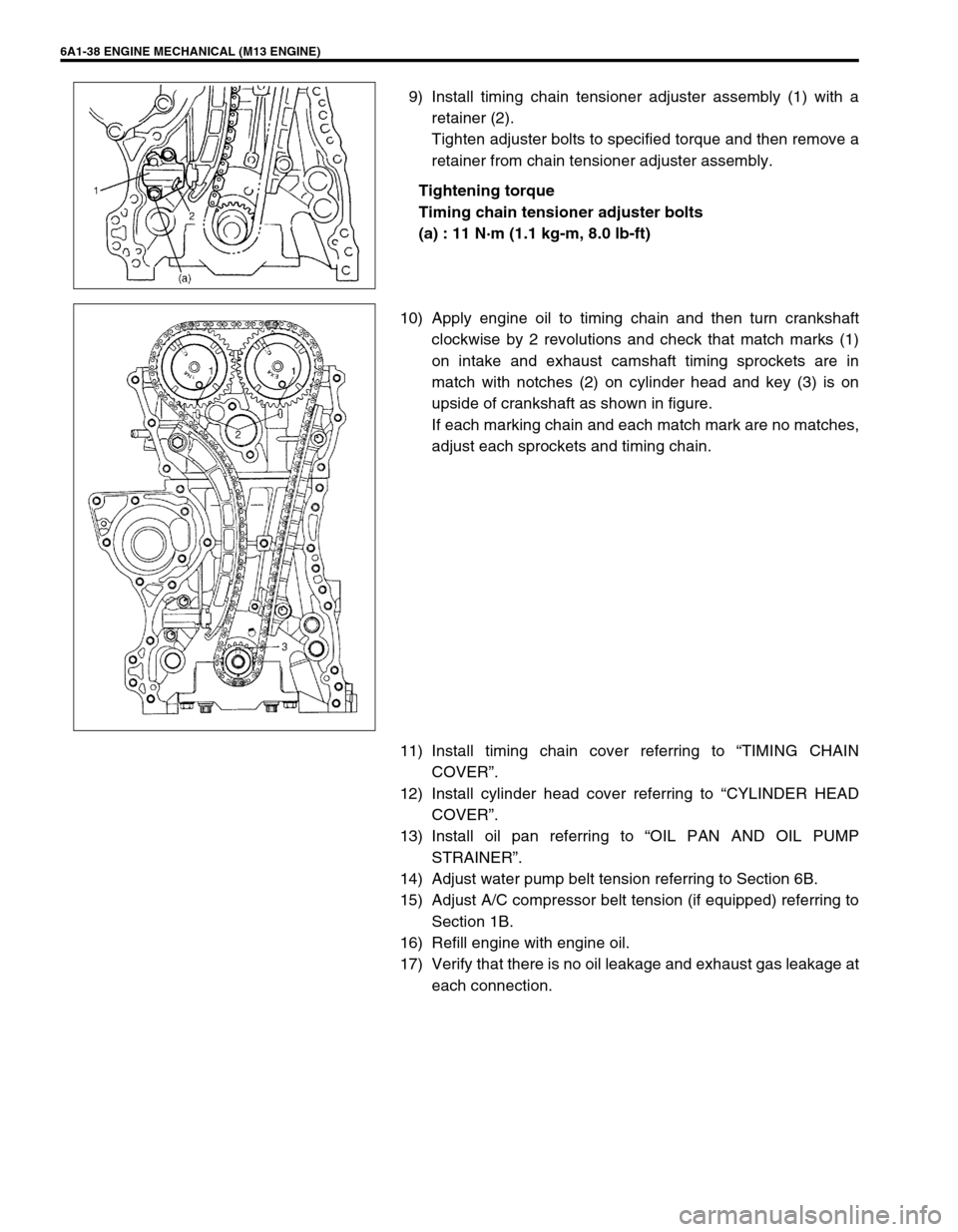
9) Install timing chain tensioner adjuster assembly (1) with a
retainer (2).
Tighten adjuster bolts to specified torque and then remove a
retainer from chain tensioner adjuster assembly.
Tightening torque
Timing chain tensioner adjuster bolts
(a) : 11 N·m (1.1 kg-m, 8.0 lb-ft)
10) Apply engine oil to timing chain and then turn crankshaft
clockwise by 2 revolutions and check that match marks (1)
on intake and exhaust camshaft timing sprockets are in
match with notches (2) on cylinder head and key (3) is on
upside of crankshaft as shown in figure.
If each marking chain and each match mark are no matches,
adjust each sprockets and timing chain.
11) Install timing chain cover referring to “TIMING CHAIN
COVER”.
12) Install cylinder head cover referring to “CYLINDER HEAD
COVER”.
13) Install oil pan referring to “OIL PAN AND OIL PUMP
STRAINER”.
14) Adjust water pump belt tension referring to Section 6B.
15) Adjust A/C compressor belt tension (if equipped) referring to
Section 1B.
16) Refill engine with engine oil.
17) Verify that there is no oil leakage and exhaust gas leakage at
each connection.
Page 544 of 698
ENGINE MECHANICAL (M13 ENGINE) 6A1-43
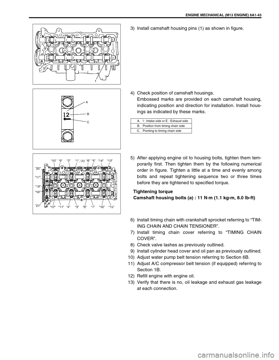
3) Install camshaft housing pins (1) as shown in figure.
4) Check position of camshaft housings.
Embossed marks are provided on each camshaft housing,
indicating position and direction for installation. Install hous-
ings as indicated by these marks.
5) After applying engine oil to housing bolts, tighten them tem-
porarily first. Then tighten them by the following numerical
order in figure. Tighten a little at a time and evenly among
bolts and repeat tightening sequence two or three times
before they are tightened to specified torque.
Tightening torque
Camshaft housing bolts (a) : 11 N·m (1.1 kg-m, 8.0 lb-ft)
6) Install timing chain with crankshaft sprocket referring to “TIM-
ING CHAIN AND CHAIN TENSIONER”.
7) Install timing chain cover referring to “TIMING CHAIN
COVER”.
8) Check valve lashes as previously outlined.
9) Install cylinder head cover and oil pan as previously outlined.
10) Adjust water pump belt tension referring to Section 6B.
11) Adjust A/C compressor belt tension (if equipped) referring to
Section 1B.
12) Refill engine with engine oil.
13) Verify that there is no, oil leakage and exhaust gas leakage
at each connection.
A. I : Intake side or E : Exhaust side
B. Position from timing chain side
C. Pointing to timing chain side
Page 557 of 698
6A1-56 ENGINE MECHANICAL (M13 ENGINE)
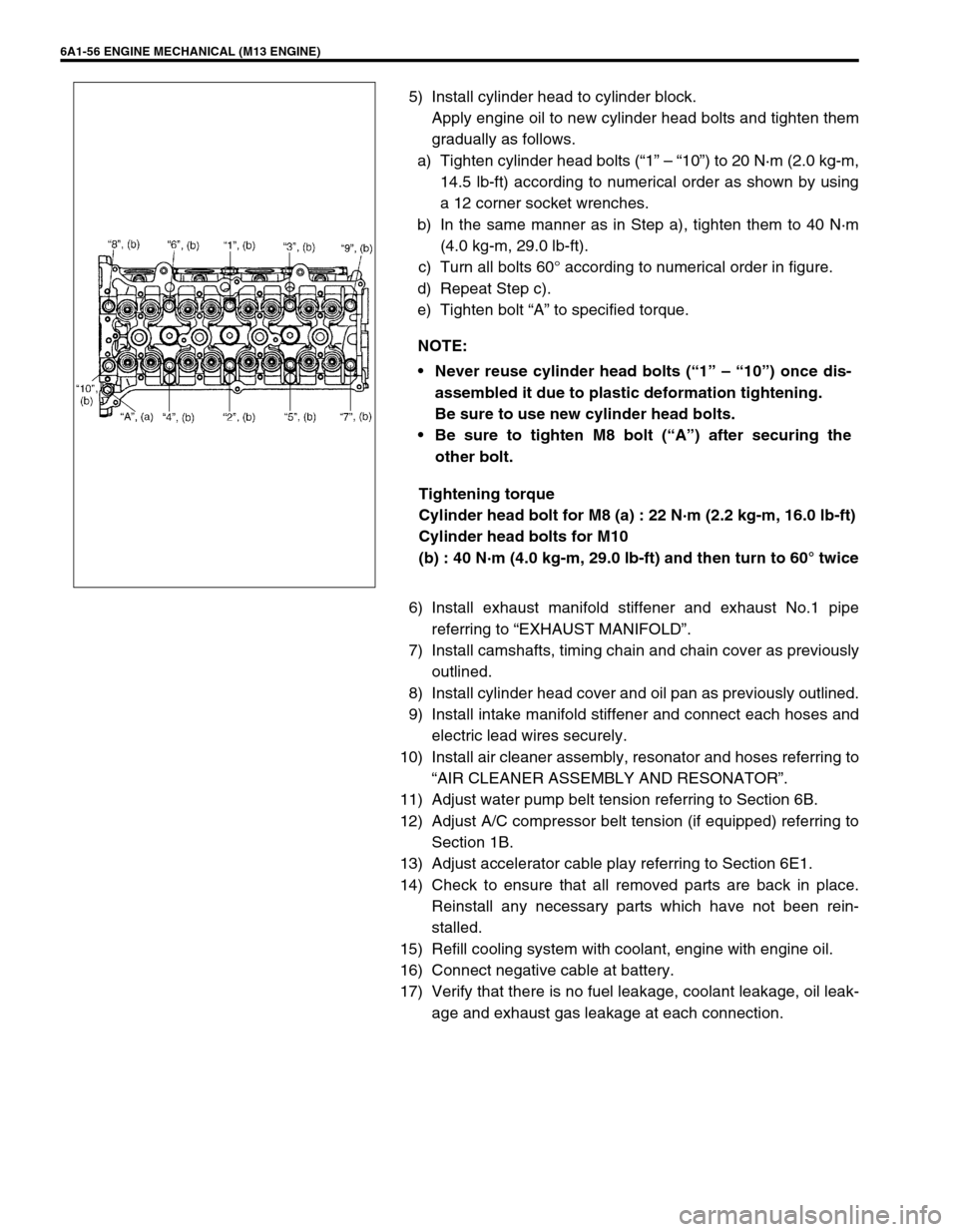
5) Install cylinder head to cylinder block.
Apply engine oil to new cylinder head bolts and tighten them
gradually as follows.
a) Tighten cylinder head bolts (“1” – “10”) to 20 N·m (2.0 kg-m,
14.5 lb-ft) according to numerical order as shown by using
a 12 corner socket wrenches.
b) In the same manner as in Step a), tighten them to 40 N·m
(4.0 kg-m, 29.0 lb-ft).
c) Turn all bolts 60° according to numerical order in figure.
d) Repeat Step c).
e) Tighten bolt “A” to specified torque.
Tightening torque
Cylinder head bolt for M8 (a) : 22 N·m (2.2 kg-m, 16.0 lb-ft)
Cylinder head bolts for M10
(b) : 40 N·m (4.0 kg-m, 29.0 lb-ft) and then turn to 60° twice
6) Install exhaust manifold stiffener and exhaust No.1 pipe
referring to “EXHAUST MANIFOLD”.
7) Install camshafts, timing chain and chain cover as previously
outlined.
8) Install cylinder head cover and oil pan as previously outlined.
9) Install intake manifold stiffener and connect each hoses and
electric lead wires securely.
10) Install air cleaner assembly, resonator and hoses referring to
“AIR CLEANER ASSEMBLY AND RESONATOR”.
11) Adjust water pump belt tension referring to Section 6B.
12) Adjust A/C compressor belt tension (if equipped) referring to
Section 1B.
13) Adjust accelerator cable play referring to Section 6E1.
14) Check to ensure that all removed parts are back in place.
Reinstall any necessary parts which have not been rein-
stalled.
15) Refill cooling system with coolant, engine with engine oil.
16) Connect negative cable at battery.
17) Verify that there is no fuel leakage, coolant leakage, oil leak-
age and exhaust gas leakage at each connection. NOTE:
Never reuse cylinder head bolts (“1” – “10”) once dis-
assembled it due to plastic deformation tightening.
Be sure to use new cylinder head bolts.
Be sure to tighten M8 bolt (“A”) after securing the
other bolt.