temperature SUZUKI SWIFT 2000 1.G RG413 Service Owner's Manual
[x] Cancel search | Manufacturer: SUZUKI, Model Year: 2000, Model line: SWIFT, Model: SUZUKI SWIFT 2000 1.GPages: 698, PDF Size: 16.01 MB
Page 77 of 698
1B-12 AIR CONDITIONING (OPTIONAL)
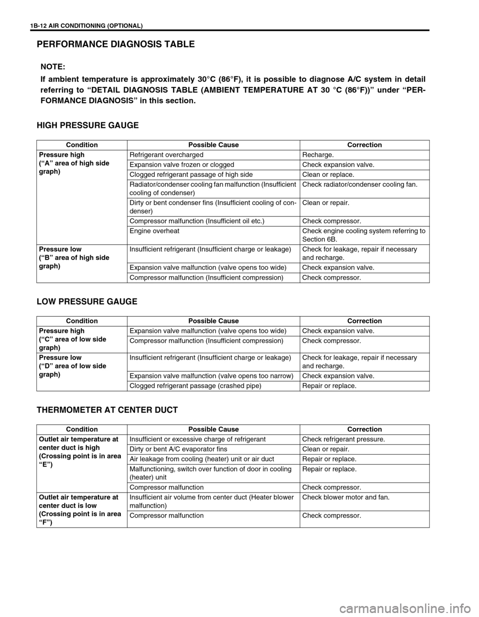
PERFORMANCE DIAGNOSIS TABLE
HIGH PRESSURE GAUGE
LOW PRESSURE GAUGE
THERMOMETER AT CENTER DUCT
NOTE:
If ambient temperature is approximately 30°C (86°F), it is possible to diagnose A/C system in detail
referring to “DETAIL DIAGNOSIS TABLE (AMBIENT TEMPERATURE AT 30 °C (86°F))” under “PER-
FORMANCE DIAGNOSIS” in this section.
Condition Possible Cause Correction
Pressure high
(“A” area of high side
graph)Refrigerant overcharged Recharge.
Expansion valve frozen or clogged Check expansion valve.
Clogged refrigerant passage of high side Clean or replace.
Radiator/condenser cooling fan malfunction (Insufficient
cooling of condenser)Check radiator/condenser cooling fan.
Dirty or bent condenser fins (Insufficient cooling of con-
denser)Clean or repair.
Compressor malfunction (Insufficient oil etc.) Check compressor.
Engine overheat Check engine cooling system referring to
Section 6B.
Pressure low
(“B” area of high side
graph)Insufficient refrigerant (Insufficient charge or leakage) Check for leakage, repair if necessary
and recharge.
Expansion valve malfunction (valve opens too wide) Check expansion valve.
Compressor malfunction (Insufficient compression) Check compressor.
Condition Possible Cause Correction
Pressure high
(“C” area of low side
graph)Expansion valve malfunction (valve opens too wide) Check expansion valve.
Compressor malfunction (Insufficient compression) Check compressor.
Pressure low
(“D” area of low side
graph)Insufficient refrigerant (Insufficient charge or leakage) Check for leakage, repair if necessary
and recharge.
Expansion valve malfunction (valve opens too narrow) Check expansion valve.
Clogged refrigerant passage (crashed pipe) Repair or replace.
Condition Possible Cause Correction
Outlet air temperature at
center duct is high
(Crossing point is in area
“E”)Insufficient or excessive charge of refrigerant Check refrigerant pressure.
Dirty or bent A/C evaporator fins Clean or repair.
Air leakage from cooling (heater) unit or air duct Repair or replace.
Malfunctioning, switch over function of door in cooling
(heater) unitRepair or replace.
Compressor malfunction Check compressor.
Outlet air temperature at
center duct is low
(Crossing point is in area
“F”)Insufficient air volume from center duct (Heater blower
malfunction)Check blower motor and fan.
Compressor malfunction Check compressor.
Page 78 of 698
AIR CONDITIONING (OPTIONAL) 1B-13
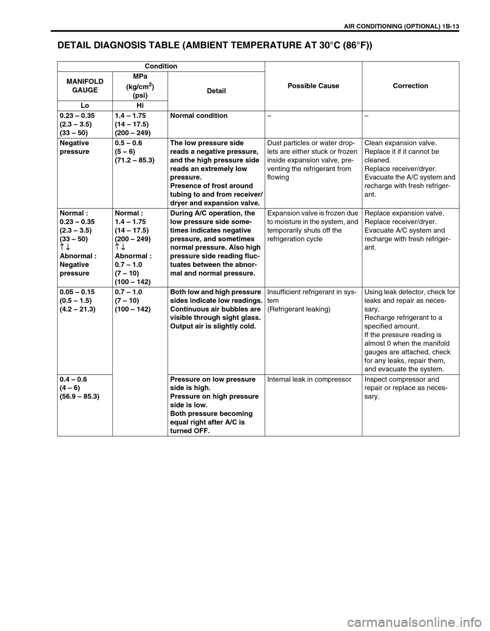
DETAIL DIAGNOSIS TABLE (AMBIENT TEMPERATURE AT 30°C (86°F))
Condition
Possible Cause Correction MANIFOLD
GAUGEMPa
(kg/cm
2)
(psi)Detail
Lo Hi
0.23 – 0.35
(2.3 – 3.5)
(33 – 50)1.4 – 1.75
(14 – 17.5)
(200 – 249)Normal condition––
Negative
pressure0.5 – 0.6
(5 – 6)
(71.2 – 85.3)The low pressure side
reads a negative pressure,
and the high pressure side
reads an extremely low
pressure.
Presence of frost around
tubing to and from receiver/
dryer and expansion valve.Dust particles or water drop-
lets are either stuck or frozen
inside expansion valve, pre-
venting the refrigerant from
flowingClean expansion valve.
Replace it if it cannot be
cleaned.
Replace receiver/dryer.
Evacuate the A/C system and
recharge with fresh refriger-
ant.
Normal :
0.23 – 0.35
(2.3 – 3.5)
(33 – 50)
↑ ↓
↑ ↓↑ ↓ ↑ ↓
Abnormal :
Negative
pressureNormal :
1.4 – 1.75
(14 – 17.5)
(200 – 249)
↑ ↓
↑ ↓↑ ↓ ↑ ↓
Abnormal :
0.7 – 1.0
(7 – 10)
(100 – 142)During A/C operation, the
low pressure side some-
times indicates negative
pressure, and sometimes
normal pressure. Also high
pressure side reading fluc-
tuates between the abnor-
mal and normal pressure.Expansion valve is frozen due
to moisture in the system, and
temporarily shuts off the
refrigeration cycleReplace expansion valve.
Replace receiver/dryer.
Evacuate A/C system and
recharge with fresh refriger-
ant.
0.05 – 0.15
(0.5 – 1.5)
(4.2 – 21.3)0.7 – 1.0
(7 – 10)
(100 – 142)Both low and high pressure
sides indicate low readings.
Continuous air bubbles are
visible through sight glass.
Output air is slightly cold.Insufficient refrigerant in sys-
tem
(Refrigerant leaking)Using leak detector, check for
leaks and repair as neces-
sary.
Recharge refrigerant to a
specified amount.
If the pressure reading is
almost 0 when the manifold
gauges are attached, check
for any leaks, repair them,
and evacuate the system.
0.4 – 0.6
(4 – 6)
(56.9 – 85.3)Pressure on low pressure
side is high.
Pressure on high pressure
side is low.
Both pressure becoming
equal right after A/C is
turned OFF.Internal leak in compressor Inspect compressor and
repair or replace as neces-
sary.
Page 81 of 698
1B-16 AIR CONDITIONING (OPTIONAL)
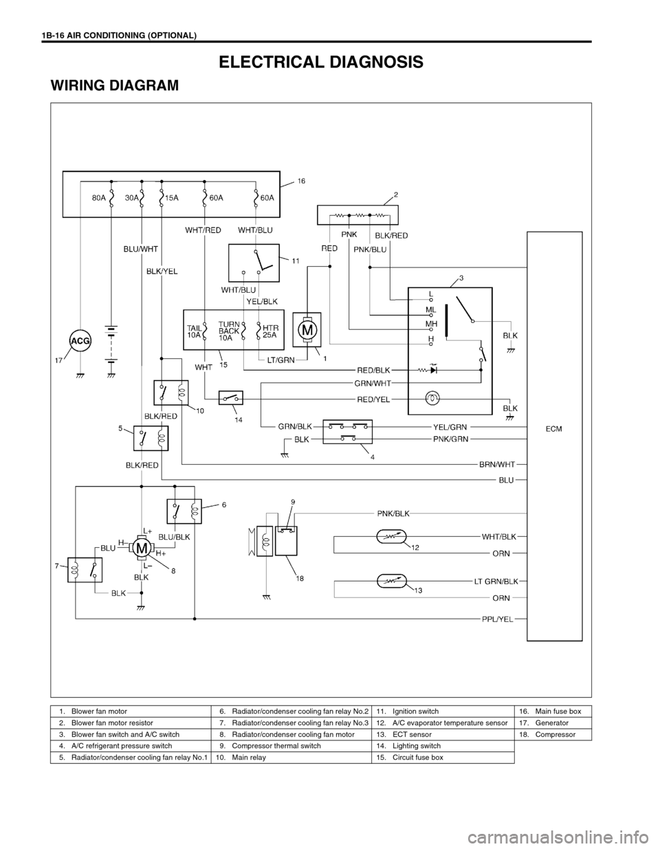
ELECTRICAL DIAGNOSIS
WIRING DIAGRAM
1. Blower fan motor 6. Radiator/condenser cooling fan relay No.2 11. Ignition switch 16. Main fuse box
2. Blower fan motor resistor 7. Radiator/condenser cooling fan relay No.3 12. A/C evaporator temperature sensor 17. Generator
3. Blower fan switch and A/C switch 8. Radiator/condenser cooling fan motor 13. ECT sensor 18. Compressor
4. A/C refrigerant pressure switch 9. Compressor thermal switch 14. Lighting switch
5. Radiator/condenser cooling fan relay No.1 10. Main relay 15. Circuit fuse box
Page 83 of 698
1B-18 AIR CONDITIONING (OPTIONAL)
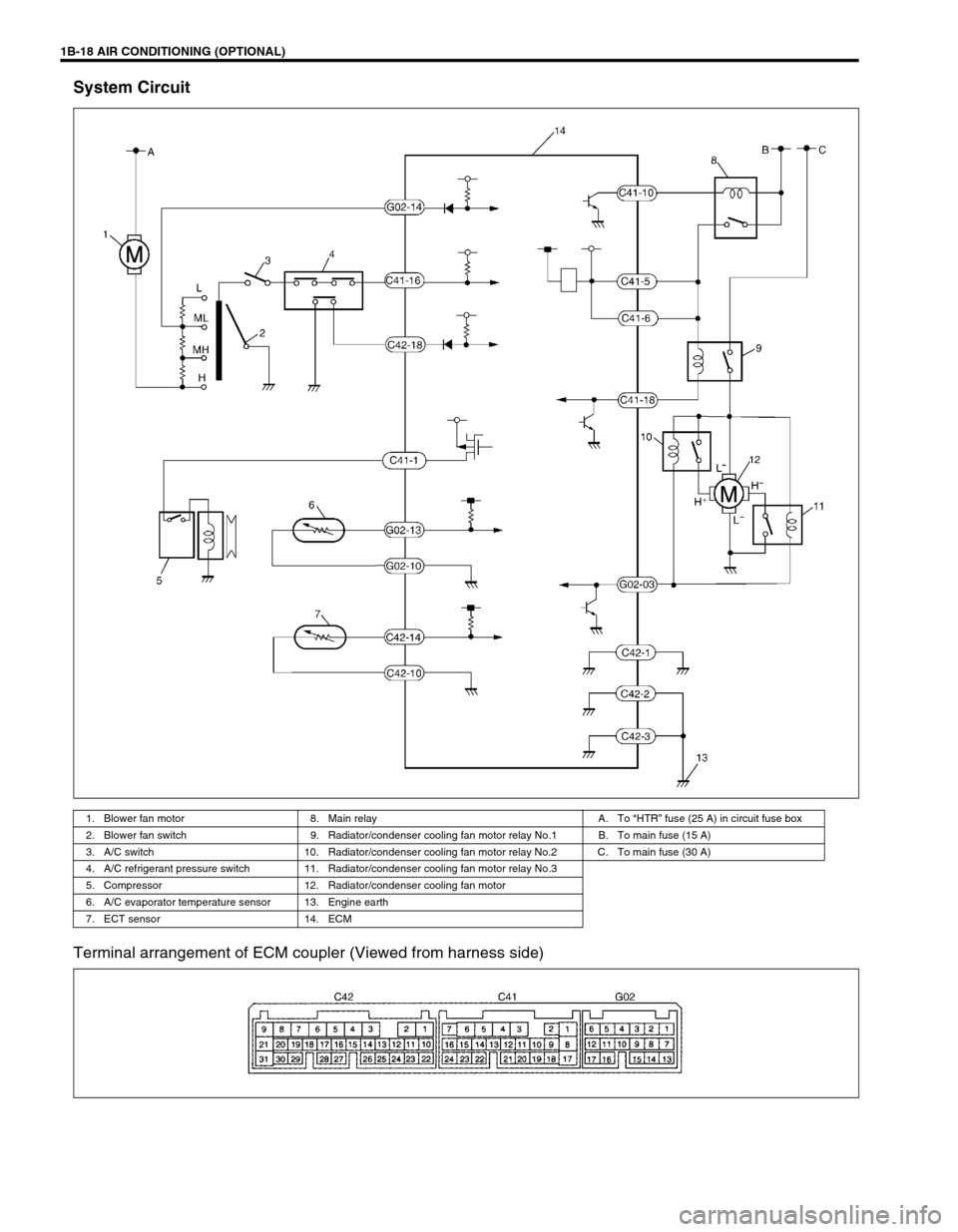
System Circuit
Terminal arrangement of ECM coupler (Viewed from harness side)
1. Blower fan motor 8. Main relay A. To “HTR” fuse (25 A) in circuit fuse box
2. Blower fan switch 9. Radiator/condenser cooling fan motor relay No.1 B. To main fuse (15 A)
3. A/C switch 10. Radiator/condenser cooling fan motor relay No.2 C. To main fuse (30 A)
4. A/C refrigerant pressure switch 11. Radiator/condenser cooling fan motor relay No.3
5. Compressor 12. Radiator/condenser cooling fan motor
6. A/C evaporator temperature sensor 13. Engine earth
7. ECT sensor 14. ECM
Page 84 of 698
AIR CONDITIONING (OPTIONAL) 1B-19
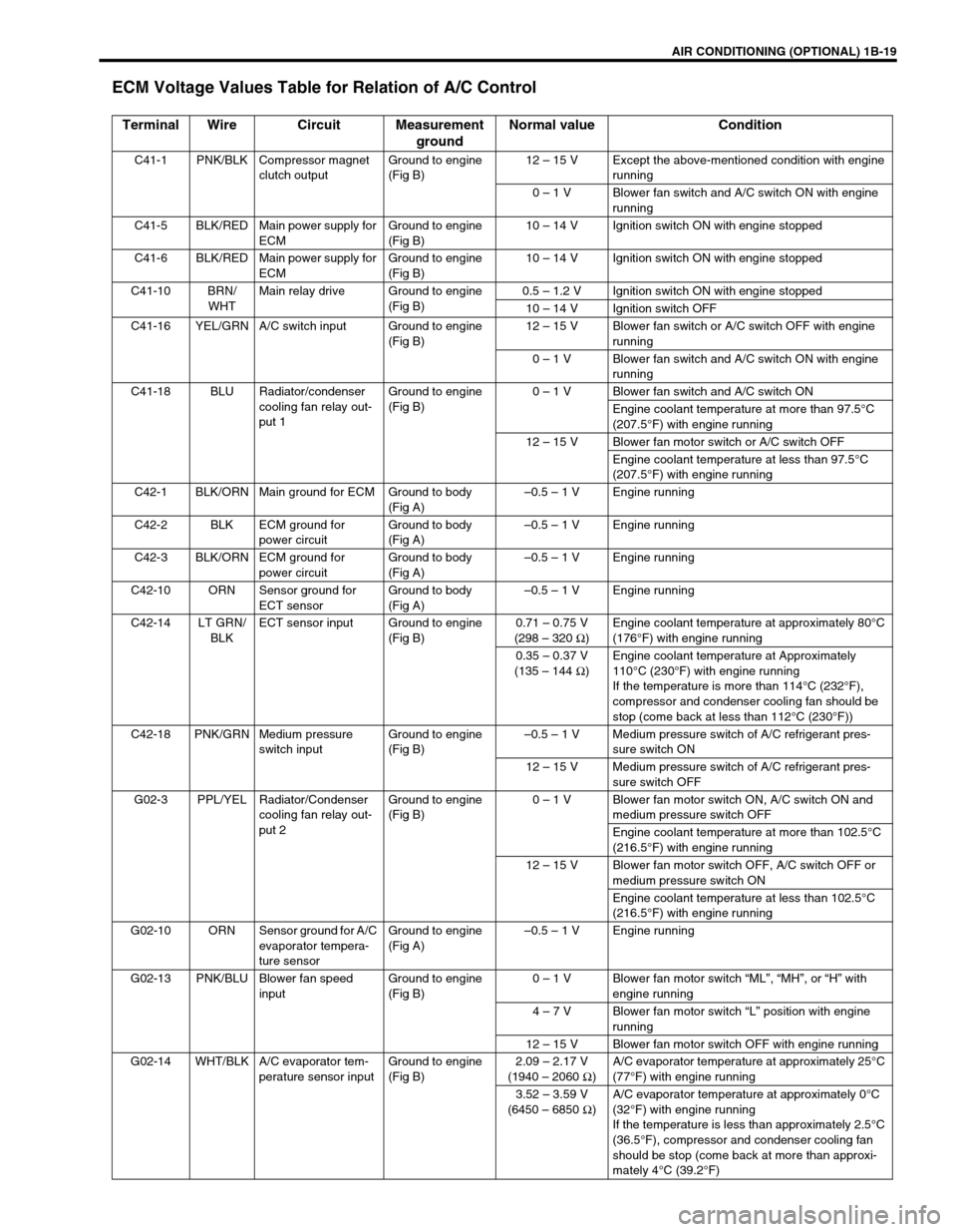
ECM Voltage Values Table for Relation of A/C Control
Terminal Wire Circuit Measurement
groundNormal value Condition
C41-1 PNK/BLK Compressor magnet
clutch outputGround to engine
(Fig B)12 – 15 V Except the above-mentioned condition with engine
running
0 – 1 V Blower fan switch and A/C switch ON with engine
running
C41-5 BLK/RED Main power supply for
ECMGround to engine
(Fig B)10 – 14 V Ignition switch ON with engine stopped
C41-6 BLK/RED Main power supply for
ECMGround to engine
(Fig B)10 – 14 V Ignition switch ON with engine stopped
C41-10 BRN/
WHTMain relay drive Ground to engine
(Fig B)0.5 – 1.2 V Ignition switch ON with engine stopped
10 – 14 V Ignition switch OFF
C41-16 YEL/GRN A/C switch input Ground to engine
(Fig B)12 – 15 V Blower fan switch or A/C switch OFF with engine
running
0 – 1 V Blower fan switch and A/C switch ON with engine
running
C41-18 BLU Radiator/condenser
cooling fan relay out-
put 1Ground to engine
(Fig B)0 – 1 V Blower fan switch and A/C switch ON
Engine coolant temperature at more than 97.5°C
(207.5°F) with engine running
12 – 15 V Blower fan motor switch or A/C switch OFF
Engine coolant temperature at less than 97.5°C
(207.5°F) with engine running
C42-1 BLK/ORN Main ground for ECM Ground to body
(Fig A)–0.5 – 1 V Engine running
C42-2 BLK ECM ground for
power circuitGround to body
(Fig A)–0.5 – 1 V Engine running
C42-3 BLK/ORN ECM ground for
power circuitGround to body
(Fig A)–0.5 – 1 V Engine running
C42-10 ORN Sensor ground for
ECT sensorGround to body
(Fig A)–0.5 – 1 V Engine running
C42-14 LT GRN/
BLKECT sensor input Ground to engine
(Fig B)0.71 – 0.75 V
(298 – 320 Ω
)Engine coolant temperature at approximately 80°C
(176°F) with engine running
0.35 – 0.37 V
(135 – 144 Ω
)Engine coolant temperature at Approximately
110°C (230°F) with engine running
If the temperature is more than 114°C (232°F),
compressor and condenser cooling fan should be
stop (come back at less than 112°C (230°F))
C42-18 PNK/GRN Medium pressure
switch inputGround to engine
(Fig B)–0.5 – 1 V Medium pressure switch of A/C refrigerant pres-
sure switch ON
12 – 15 V Medium pressure switch of A/C refrigerant pres-
sure switch OFF
G02-3 PPL/YEL Radiator/Condenser
cooling fan relay out-
put 2Ground to engine
(Fig B)0 – 1 V Blower fan motor switch ON, A/C switch ON and
medium pressure switch OFF
Engine coolant temperature at more than 102.5°C
(216.5°F) with engine running
12 – 15 V Blower fan motor switch OFF, A/C switch OFF or
medium pressure switch ON
Engine coolant temperature at less than 102.5°C
(216.5°F) with engine running
G02-10 ORN Sensor ground for A/C
evaporator tempera-
ture sensorGround to engine
(Fig A)–0.5 – 1 V Engine running
G02-13 PNK/BLU Blower fan speed
inputGround to engine
(Fig B)0 – 1 V Blower fan motor switch “ML”, “MH”, or “H” with
engine running
4 – 7 V Blower fan motor switch “L” position with engine
running
12 – 15 V Blower fan motor switch OFF with engine running
G02-14 WHT/BLK A/C evaporator tem-
perature sensor inputGround to engine
(Fig B)2.09 – 2.17 V
(1940 – 2060 Ω
)A/C evaporator temperature at approximately 25°C
(77°F) with engine running
3.52 – 3.59 V
(6450 – 6850 Ω
)A/C evaporator temperature at approximately 0°C
(32°F) with engine running
If the temperature is less than approximately 2.5°C
(36.5°F), compressor and condenser cooling fan
should be stop (come back at more than approxi-
mately 4°C (39.2°F)
Page 85 of 698
1B-20 AIR CONDITIONING (OPTIONAL)
REFRIGERANT RECOVERY, EVACUATING AND CHARGING
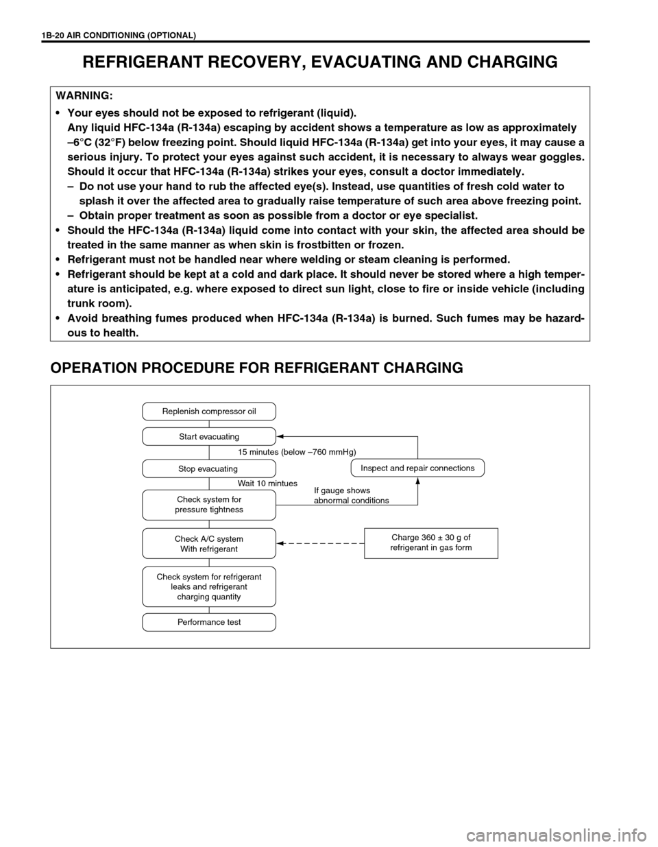
OPERATION PROCEDURE FOR REFRIGERANT CHARGING
WARNING:
Your eyes should not be exposed to refrigerant (liquid).
Any liquid HFC-134a (R-134a) escaping by accident shows a temperature as low as approximately
–6°C (32°F) below freezing point. Should liquid HFC-134a (R-134a) get into your eyes, it may cause a
serious injury. To protect your eyes against such accident, it is necessary to always wear goggles.
Should it occur that HFC-134a (R-134a) strikes your eyes, consult a doctor immediately.
– Do not use your hand to rub the affected eye(s). Instead, use quantities of fresh cold water to
splash it over the affected area to gradually raise temperature of such area above freezing point.
– Obtain proper treatment as soon as possible from a doctor or eye specialist.
Should the HFC-134a (R-134a) liquid come into contact with your skin, the affected area should be
treated in the same manner as when skin is frostbitten or frozen.
Refrigerant must not be handled near where welding or steam cleaning is performed.
Refrigerant should be kept at a cold and dark place. It should never be stored where a high temper-
ature is anticipated, e.g. where exposed to direct sun light, close to fire or inside vehicle (including
trunk room).
Avoid breathing fumes produced when HFC-134a (R-134a) is burned. Such fumes may be hazard-
ous to health.
Replenish compressor oil
Start evacuating
Inspect and repair connections
Charge 360 ± 30 g of
refrigerant in gas form Stop evacuating 15 minutes (below –760 mmHg)
Wait 10 mintues
If gauge shows
abnormal conditions Check system for
pressure tightness
Check A/C system
With refrigerant
Check system for refrigerant
leaks and refrigerant
charging quantity
Performance test
Page 92 of 698
AIR CONDITIONING (OPTIONAL) 1B-27
ON-VEHICLE SERVICE
SERVICE PRECAUTION
When servicing air conditioning system, note the following instructions.
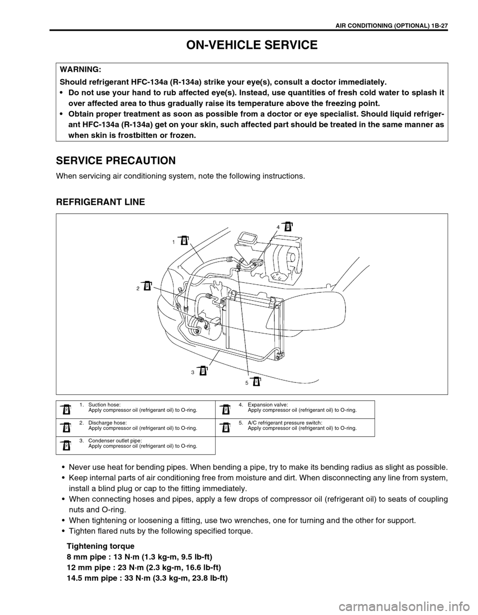
REFRIGERANT LINE
Never use heat for bending pipes. When bending a pipe, try to make its bending radius as slight as possible.
Keep internal parts of air conditioning free from moisture and dirt. When disconnecting any line from system,
install a blind plug or cap to the fitting immediately.
When connecting hoses and pipes, apply a few drops of compressor oil (refrigerant oil) to seats of coupling
nuts and O-ring.
When tightening or loosening a fitting, use two wrenches, one for turning and the other for support.
Tighten flared nuts by the following specified torque.
Tightening torque
8 mm pipe : 13 N·m (1.3 kg-m, 9.5 lb-ft)
12 mm pipe : 23 N·m (2.3 kg-m, 16.6 lb-ft)
14.5 mm pipe : 33 N·m (3.3 kg-m, 23.8 lb-ft) WARNING:
Should refrigerant HFC-134a (R-134a) strike your eye(s), consult a doctor immediately.
Do not use your hand to rub affected eye(s). Instead, use quantities of fresh cold water to splash it
over affected area to thus gradually raise its temperature above the freezing point.
Obtain proper treatment as soon as possible from a doctor or eye specialist. Should liquid refriger-
ant HFC-134a (R-134a) get on your skin, such affected part should be treated in the same manner as
when skin is frostbitten or frozen.
1. Suction hose:
Apply compressor oil (refrigerant oil) to O-ring.4. Expansion valve:
Apply compressor oil (refrigerant oil) to O-ring.
2. Discharge hose:
Apply compressor oil (refrigerant oil) to O-ring.5. A/C refrigerant pressure switch:
Apply compressor oil (refrigerant oil) to O-ring.
3. Condenser outlet pipe:
Apply compressor oil (refrigerant oil) to O-ring.
Page 97 of 698
1B-32 AIR CONDITIONING (OPTIONAL)
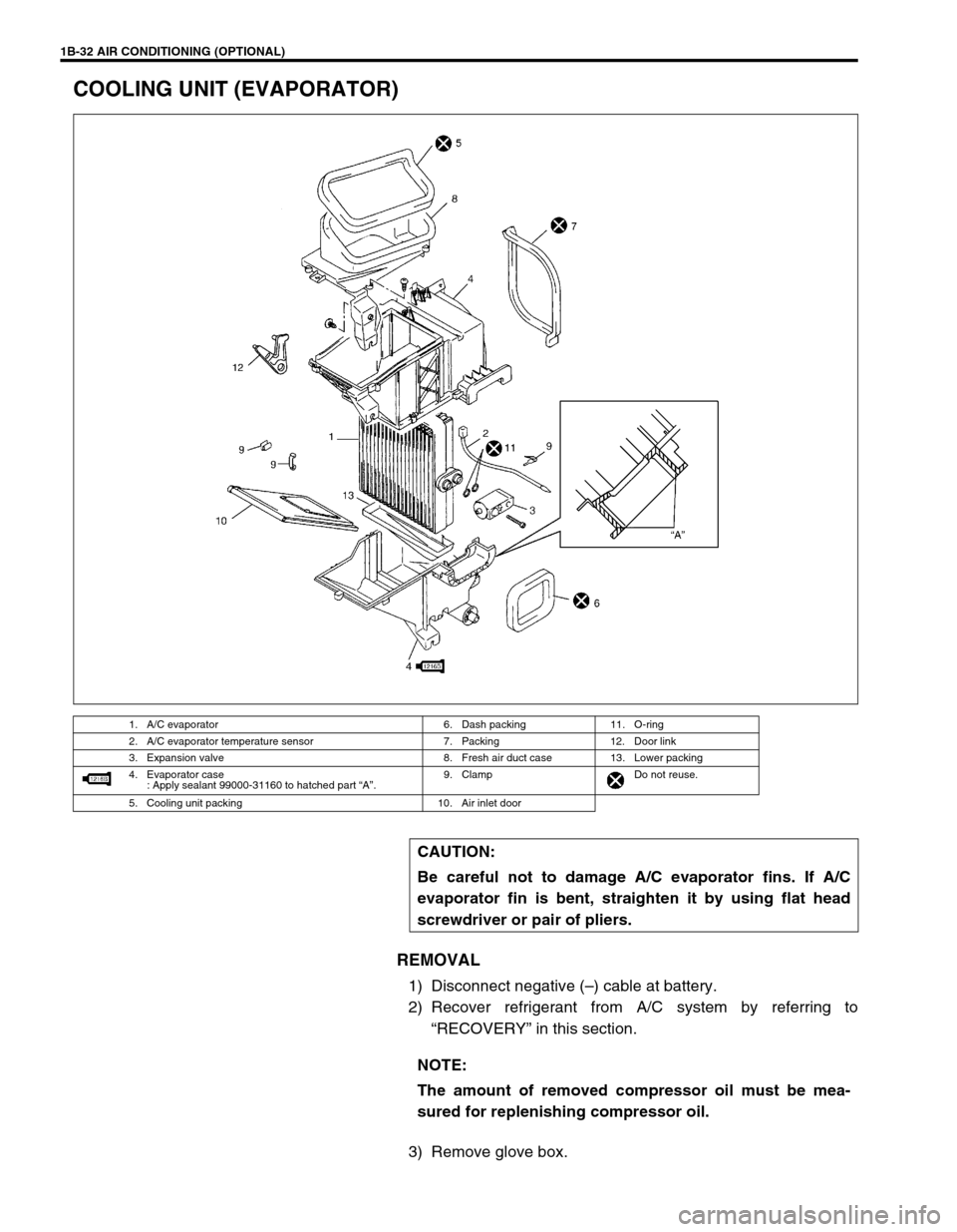
COOLING UNIT (EVAPORATOR)
REMOVAL
1) Disconnect negative (–) cable at battery.
2) Recover refrigerant from A/C system by referring to
“RECOVERY” in this section.
3) Remove glove box.
1. A/C evaporator 6. Dash packing 11. O-ring
2. A/C evaporator temperature sensor 7. Packing 12. Door link
3. Expansion valve 8. Fresh air duct case 13. Lower packing
4. Evaporator case
: Apply sealant 99000-31160 to hatched part “A”.9. Clamp Do not reuse.
5. Cooling unit packing 10. Air inlet door
CAUTION:
Be careful not to damage A/C evaporator fins. If A/C
evaporator fin is bent, straighten it by using flat head
screwdriver or pair of pliers.
NOTE:
The amount of removed compressor oil must be mea-
sured for replenishing compressor oil.
Page 98 of 698
AIR CONDITIONING (OPTIONAL) 1B-33
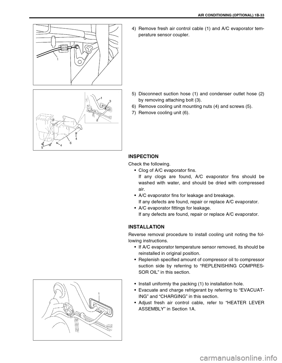
4) Remove fresh air control cable (1) and A/C evaporator tem-
perature sensor coupler.
5) Disconnect suction hose (1) and condenser outlet hose (2)
by removing attaching bolt (3).
6) Remove cooling unit mounting nuts (4) and screws (5).
7) Remove cooling unit (6).
INSPECTION
Check the following.
Clog of A/C evaporator fins.
If any clogs are found, A/C evaporator fins should be
washed with water, and should be dried with compressed
air.
A/C evaporator fins for leakage and breakage.
If any defects are found, repair or replace A/C evaporator.
A/C evaporator fittings for leakage.
If any defects are found, repair or replace A/C evaporator.
INSTALLATION
Reverse removal procedure to install cooling unit noting the fol-
lowing instructions.
If A/C evaporator temperature sensor removed, its should be
reinstalled in original position.
Replenish specified amount of compressor oil to compressor
suction side by referring to “REPLENISHING COMPRES-
SOR OIL” in this section.
Install uniformly the packing (1) to installation hole.
Evacuate and charge refrigerant by referring to “EVACUAT-
ING” and “CHARGING” in this section.
Adjust fresh air control cable, refer to “HEATER LEVER
ASSEMBLY” in Section 1A.
Page 99 of 698
1B-34 AIR CONDITIONING (OPTIONAL)
A/C EVAPORATOR TEMPERATURE SENSOR
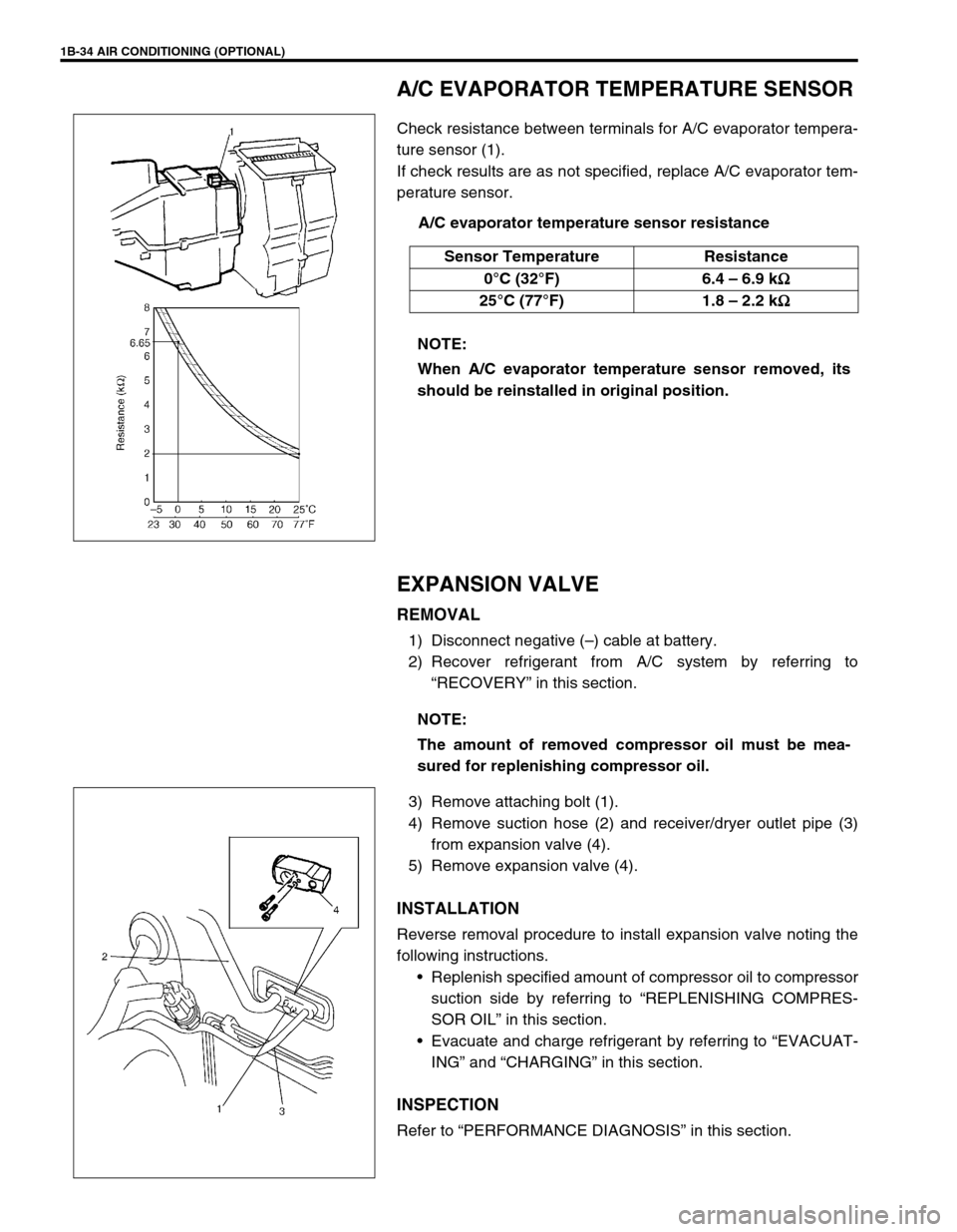
Check resistance between terminals for A/C evaporator tempera-
ture sensor (1).
If check results are as not specified, replace A/C evaporator tem-
perature sensor.
A/C evaporator temperature sensor resistance
EXPANSION VALVE
REMOVAL
1) Disconnect negative (–) cable at battery.
2) Recover refrigerant from A/C system by referring to
“RECOVERY” in this section.
3) Remove attaching bolt (1).
4) Remove suction hose (2) and receiver/dryer outlet pipe (3)
from expansion valve (4).
5) Remove expansion valve (4).
INSTALLATION
Reverse removal procedure to install expansion valve noting the
following instructions.
Replenish specified amount of compressor oil to compressor
suction side by referring to “REPLENISHING COMPRES-
SOR OIL” in this section.
Evacuate and charge refrigerant by referring to “EVACUAT-
ING” and “CHARGING” in this section.
INSPECTION
Refer to “PERFORMANCE DIAGNOSIS” in this section. Sensor Temperature Resistance
0°C (32°F) 6.4 – 6.9 k
Ω
ΩΩ Ω
25°C (77°F) 1.8 – 2.2 k
Ω
ΩΩ Ω
NOTE:
When A/C evaporator temperature sensor removed, its
should be reinstalled in original position.
NOTE:
The amount of removed compressor oil must be mea-
sured for replenishing compressor oil.