temperature SUZUKI SWIFT 2000 1.G RG413 Service Repair Manual
[x] Cancel search | Manufacturer: SUZUKI, Model Year: 2000, Model line: SWIFT, Model: SUZUKI SWIFT 2000 1.GPages: 698, PDF Size: 16.01 MB
Page 472 of 698
ENGINE GENERAL INFORMATION AND DIAGNOSIS 6-103
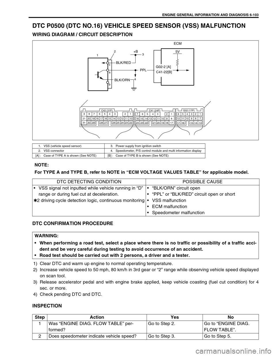
DTC P0500 (DTC NO.16) VEHICLE SPEED SENSOR (VSS) MALFUNCTION
WIRING DIAGRAM / CIRCUIT DESCRIPTION
DTC CONFIRMATION PROCEDURE
1) Clear DTC and warm up engine to normal operating temperature.
2) Increase vehicle speed to 50 mph, 80 km/h in 3rd gear or “2” range while observing vehicle speed displayed
on scan tool.
3) Release accelerator pedal and with engine brake applied, keep vehicle coasting (fuel cut condition) for 4
sec. or more.
4) Check pending DTC and DTC.
INSPECTION
1. VSS (vehicle speed sensor) 3. Power supply from ignition switch
2. VSS connector 4. Speedometer, P/S control module and multi information display
[A] : Case of TYPE A is shown (See NOTE) [B] : Case of TYPE B is shown (See NOTE)
ECM
5V+B
BLK/RED
BLK/ORN
PPL
C42 (31P) C41 (24P) G02 (17P)1 2 3 4 5 6 7 8 9
10 11 12 13 14 15 16 17 18 19 20 21
22 23 24 25 26 28 27 29 30 315 6
1 2 3 4 5 6 7
11 12
9 10 11 13 12 14 15 16
16 171 2
7 8
13 14 3 4
9 10
15 17 188
19 20 21 22 23 24
1
4 c
a
b2
3
G02-2 [A]
C41-22[B]
NOTE:
For TYPE A and TYPE B, refer to NOTE in “ECM VOLTAGE VALUES TABLE” for applicable model.
DTC DETECTING CONDITION POSSIBLE CAUSE
VSS signal not inputted while vehicle running in “D”
range or during fuel cut at deceleration.
✱2 driving cycle detection logic, continuous monitoring“BLK/ORN” circuit open
“PPL” or “BLK/RED” circuit open or short
VSS malfunction
ECM malfunction
Speedometer malfunction
WARNING:
When performing a road test, select a place where there is no traffic or possibility of a traffic acci-
dent and be very careful during testing to avoid occurrence of an accident.
Road test should be carried out with 2 persons, a driver and a tester.
Step Action Yes No
1Was “ENGINE DIAG. FLOW TABLE” per-
formed?Go to Step 2. Go to “ENGINE DIAG.
FLOW TABLE”.
2 Does speedometer indicate vehicle speed? Go to Step 3. Go to Step 5.
Page 505 of 698

6A1-4 ENGINE MECHANICAL (M13 ENGINE)
DIAGNOSIS
DIAGNOSIS TABLE
Refer to “ENGINE MECHANICAL DIAGNOSIS TABLE” in Sec-
tion 6.
COMPRESSION CHECK
Check compression pressure on all 4 cylinders as follows:
1) Warm up engine to normal operating temperature.
2) Stop engine after warming up.
3) Remove air cleaner assembly (1), resonator (2) and hoses.
Refer to “AIR CLEANER ASSEMBLY AND RESONATOR”.
4) Remove cylinder head upper cover (1).
5) Disconnect ignition coil couplers (1).
6) Remove ignition coil assemblies (2) with high-tension cord
(3).
7) Remove all spark plugs.
8) Disconnect fuel injector wires (4) at the coupler.NOTE:
After warming up engine, place transmission gear shift
lever in “Neutral” (shift selector lever to “P” range for A/T
model), and set parking brake and block drive wheels.
Page 507 of 698
6A1-6 ENGINE MECHANICAL (M13 ENGINE)
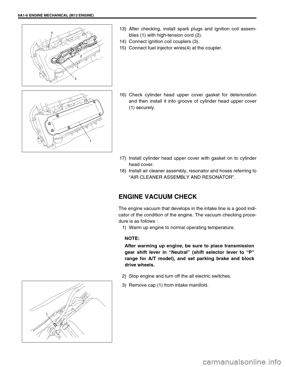
13) After checking, install spark plugs and ignition coil assem-
blies (1) with high-tension cord (2).
14) Connect ignition coil couplers (3).
15) Connect fuel injector wires(4) at the coupler.
16) Check cylinder head upper cover gasket for deterioration
and then install it into groove of cylinder head upper cover
(1) securely.
17) Install cylinder head upper cover with gasket on to cylinder
head cover.
18) Install air cleaner assembly, resonator and hoses referring to
“AIR CLEANER ASSEMBLY AND RESONATOR”.
ENGINE VACUUM CHECK
The engine vacuum that develops in the intake line is a good indi-
cator of the condition of the engine. The vacuum checking proce-
dure is as follows :
1) Warm up engine to normal operating temperature.
2) Stop engine and turn off the all electric switches.
3) Remove cap (1) from intake manifold.
NOTE:
After warming up engine, be sure to place transmission
gear shift lever in “Neutral” (shift selector lever to “P”
range for A/T model), and set parking brake and block
drive wheels.
Page 510 of 698
ENGINE MECHANICAL (M13 ENGINE) 6A1-9
VALVE LASH (CLEARANCE)
INSPECTION
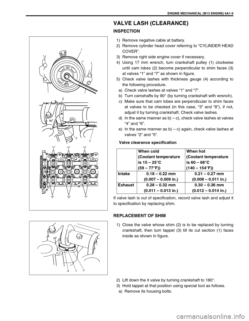
1) Remove negative cable at battery.
2) Remove cylinder head cover referring to “CYLINDER HEAD
COVER”.
3) Remove right side engine cover if necessary.
4) Using 17 mm wrench, turn crankshaft pulley (1) clockwise
until cam lobes (2) become perpendicular to shim faces (3)
at valves “1” and “7” as shown in figure.
5) Check valve lashes with thickness gauge (4) according to
the following procedure.
a) Check valve lashes at valves “1” and “7”.
b) Turn camshafts by 90° (by turning crankshaft with wrench).
c) Make sure that cam lobes are perpendicular to shim faces
at valves to be checked (in this case, “3” and “8”), if not,
adjust it by turning crankshaft. Check valve lashes.
d) In the same manner as b) – c), check valve lashes at valves
“4” and “6”.
e) In the same manner as b) – c) again, check valve lashes at
valves “2” and “5”.
Valve clearance specification
If valve lash is out of specification, record valve lash and adjust it
to specification by replacing shim.
REPLACEMENT OF SHIM
1) Close the valve whose shim (2) is to be replaced by turning
crankshaft, then turn tappet (3) till its cut section (1) faces
inside as shown in figure.
2) Lift down the it valve by turning crankshaft to 180°.
3) Hold tappet at that position using special tool as follows.
a) Remove its housing bolts.When cold
(Coolant temperature
is 15 – 25°C
(59 – 77°F))When hot
(Coolant temperature
is 60 – 68°C
(140 – 154°F))
Intake 0.18 – 0.22 mm
(0.007 – 0.009 in.)0.21 – 0.27 mm
(0.008 – 0.011 in.)
Exhaust 0.28 – 0.32 mm
(0.011 – 0.013 in.)0.30 – 0.36 mm
(0.012 – 0.014 in.)
Page 554 of 698
ENGINE MECHANICAL (M13 ENGINE) 6A1-53
ASSEMBLY
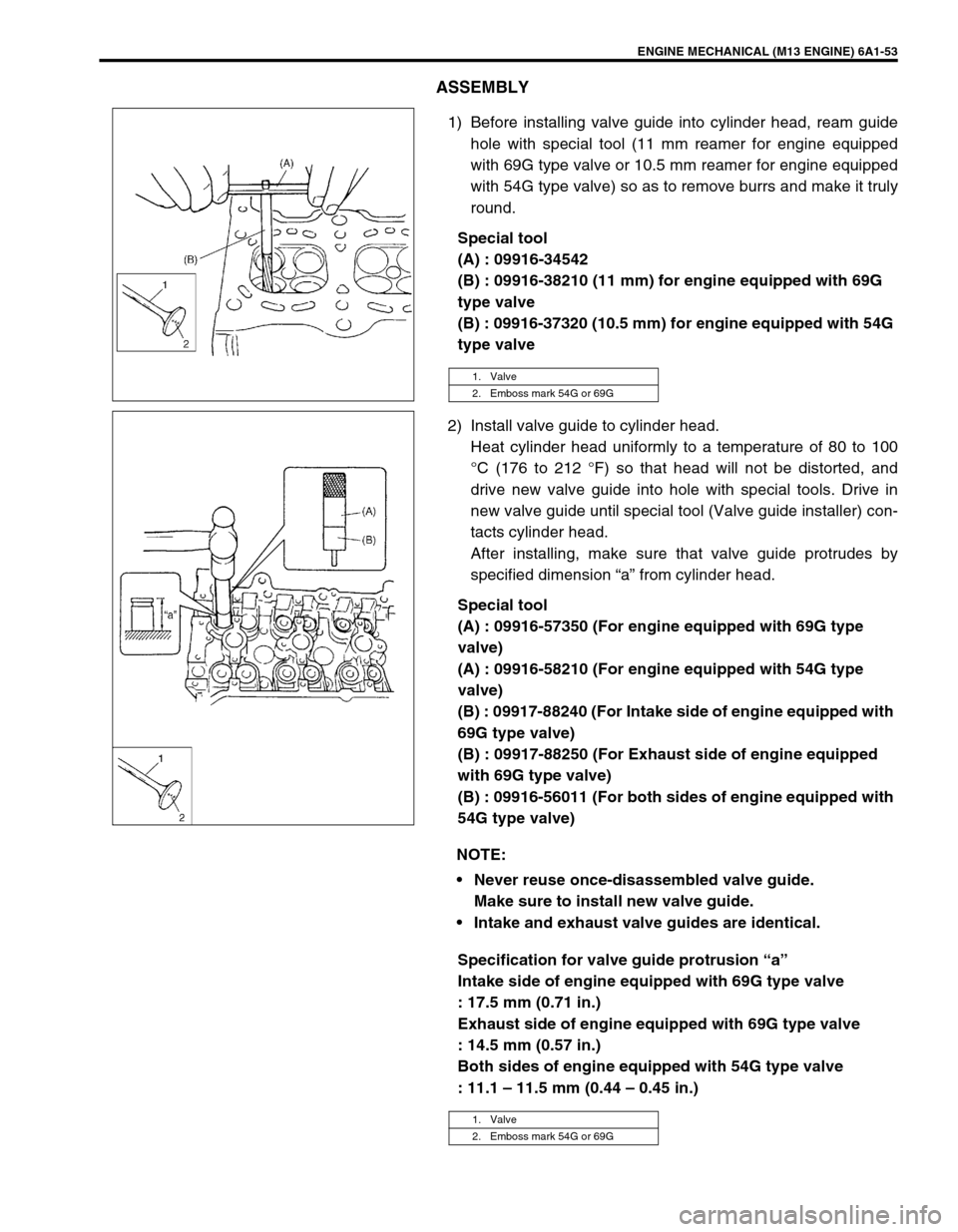
1) Before installing valve guide into cylinder head, ream guide
hole with special tool (11 mm reamer for engine equipped
with 69G type valve or 10.5 mm reamer for engine equipped
with 54G type valve) so as to remove burrs and make it truly
round.
Special tool
(A) : 09916-34542
(B) : 09916-38210 (11 mm) for engine equipped with 69G
type valve
(B) : 09916-37320 (10.5 mm) for engine equipped with 54G
type valve
2) Install valve guide to cylinder head.
Heat cylinder head uniformly to a temperature of 80 to 100
°C (176 to 212 °F) so that head will not be distorted, and
drive new valve guide into hole with special tools. Drive in
new valve guide until special tool (Valve guide installer) con-
tacts cylinder head.
After installing, make sure that valve guide protrudes by
specified dimension “a” from cylinder head.
Special tool
(A) : 09916-57350 (For engine equipped with 69G type
valve)
(A) : 09916-58210 (For engine equipped with 54G type
valve)
(B) : 09917-88240 (For Intake side of engine equipped with
69G type valve)
(B) : 09917-88250 (For Exhaust side of engine equipped
with 69G type valve)
(B) : 09916-56011 (For both sides of engine equipped with
54G type valve)
Specification for valve guide protrusion “a”
Intake side of engine equipped with 69G type valve
: 17.5 mm (0.71 in.)
Exhaust side of engine equipped with 69G type valve
: 14.5 mm (0.57 in.)
Both sides of engine equipped with 54G type valve
: 11.1 – 11.5 mm (0.44 – 0.45 in.)
1. Valve
2. Emboss mark 54G or 69G
NOTE:
Never reuse once-disassembled valve guide.
Make sure to install new valve guide.
Intake and exhaust valve guides are identical.
1. Valve
2. Emboss mark 54G or 69G
Page 591 of 698
6B-2 ENGINE COOLING
GENERAL DESCRIPTION
The cooling system consists of the radiator cap, radiator, coolant reservoir tank, hoses, water pump, cooling fan
and thermostat. The radiator is of tube-and-fin type.
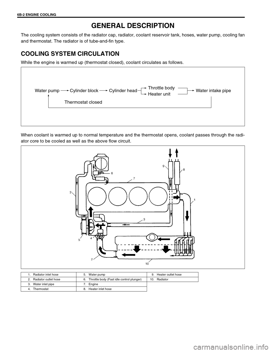
COOLING SYSTEM CIRCULATION
While the engine is warmed up (thermostat closed), coolant circulates as follows.
When coolant is warmed up to normal temperature and the thermostat opens, coolant passes through the radi-
ator core to be cooled as well as the above flow circuit.
1. Radiator inlet hose 5. Water pump 9. Heater outlet hose
2. Radiator outlet hose 6. Throttle body (Fast idle control plunger) 10. Radiator
3. Water inlet pipe 7. Engine
4. Thermostat 8. Heater inlet hose
Water pump Cylinder block
Thermostat closedCylinder head Water intake pipeThrottle body
Heater unit
Page 592 of 698
ENGINE COOLING 6B-3
COOLANT
The coolant recovery system is standard. The coolant in the radiator expands with heat, and the overflow is col-
lected in the reservoir.
When the system cools down, the coolant is drawn back into the radiator.
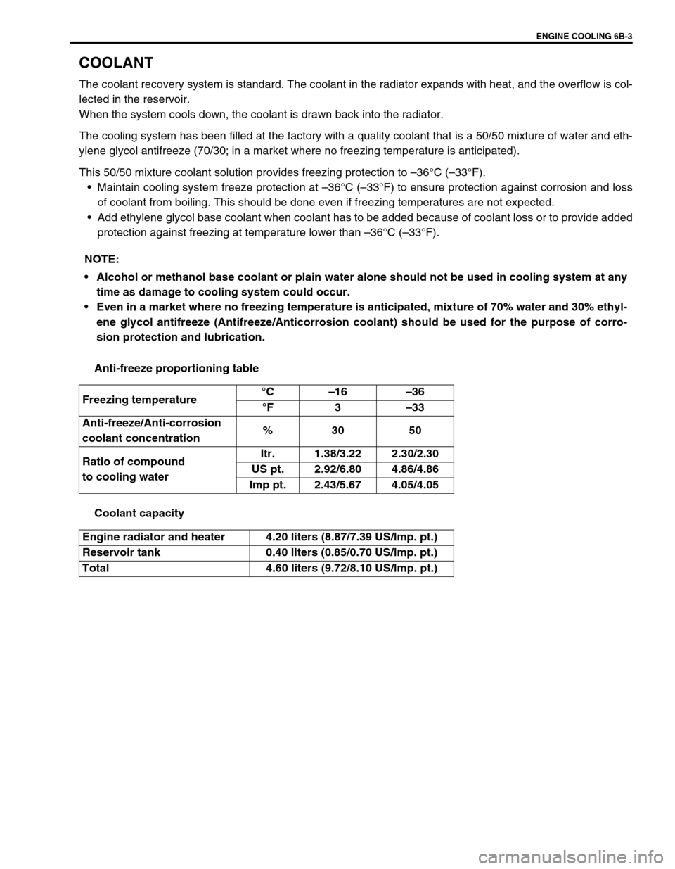
The cooling system has been filled at the factory with a quality coolant that is a 50/50 mixture of water and eth-
ylene glycol antifreeze (70/30; in a market where no freezing temperature is anticipated).
This 50/50 mixture coolant solution provides freezing protection to –36°C (–33°F).
Maintain cooling system freeze protection at –36°C (–33°F) to ensure protection against corrosion and loss
of coolant from boiling. This should be done even if freezing temperatures are not expected.
Add ethylene glycol base coolant when coolant has to be added because of coolant loss or to provide added
protection against freezing at temperature lower than –36°C (–33°F).
Anti-freeze proportioning table
Coolant capacity NOTE:
Alcohol or methanol base coolant or plain water alone should not be used in cooling system at any
time as damage to cooling system could occur.
Even in a market where no freezing temperature is anticipated, mixture of 70% water and 30% ethyl-
ene glycol antifreeze (Antifreeze/Anticorrosion coolant) should be used for the purpose of corro-
sion protection and lubrication.
Freezing temperature°C–16–36
°F3–33
Anti-freeze/Anti-corrosion
coolant concentration%30 50
Ratio of compound
to cooling waterItr. 1.38/3.22 2.30/2.30
US pt. 2.92/6.80 4.86/4.86
Imp pt. 2.43/5.67 4.05/4.05
Engine radiator and heater 4.20 liters (8.87/7.39 US/lmp. pt.)
Reservoir tank 0.40 liters (0.85/0.70 US/lmp. pt.)
Total 4.60 liters (9.72/8.10 US/lmp. pt.)
Page 595 of 698
6B-6 ENGINE COOLING
MAINTENANCE
COOLANT LEVEL CHECK
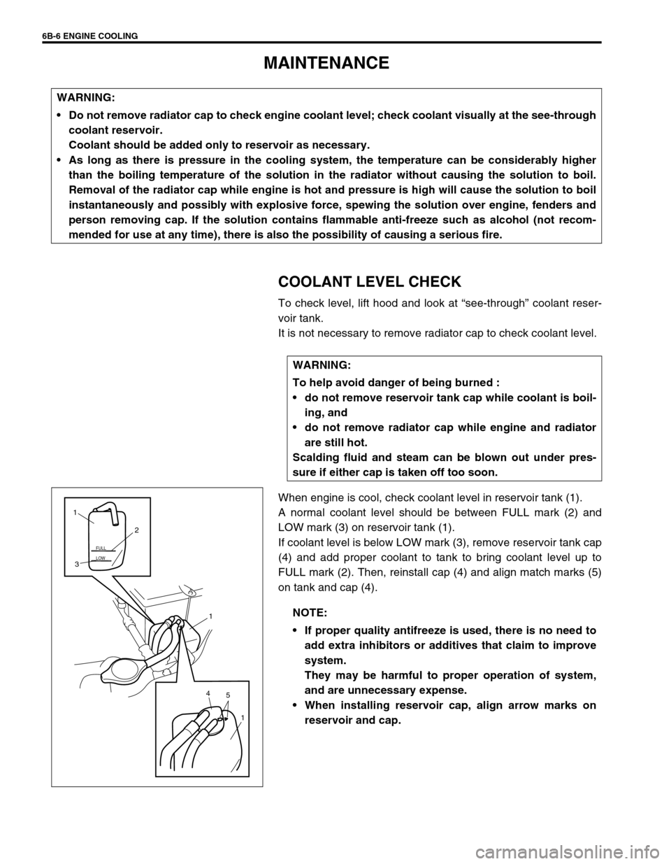
To check level, lift hood and look at “see-through” coolant reser-
voir tank.
It is not necessary to remove radiator cap to check coolant level.
When engine is cool, check coolant level in reservoir tank (1).
A normal coolant level should be between FULL mark (2) and
LOW mark (3) on reservoir tank (1).
If coolant level is below LOW mark (3), remove reservoir tank cap
(4) and add proper coolant to tank to bring coolant level up to
FULL mark (2). Then, reinstall cap (4) and align match marks (5)
on tank and cap (4). WARNING:
Do not remove radiator cap to check engine coolant level; check coolant visually at the see-through
coolant reservoir.
Coolant should be added only to reservoir as necessary.
As long as there is pressure in the cooling system, the temperature can be considerably higher
than the boiling temperature of the solution in the radiator without causing the solution to boil.
Removal of the radiator cap while engine is hot and pressure is high will cause the solution to boil
instantaneously and possibly with explosive force, spewing the solution over engine, fenders and
person removing cap. If the solution contains flammable anti-freeze such as alcohol (not recom-
mended for use at any time), there is also the possibility of causing a serious fire.
WARNING:
To help avoid danger of being burned :
do not remove reservoir tank cap while coolant is boil-
ing, and
do not remove radiator cap while engine and radiator
are still hot.
Scalding fluid and steam can be blown out under pres-
sure if either cap is taken off too soon.
NOTE:
If proper quality antifreeze is used, there is no need to
add extra inhibitors or additives that claim to improve
system.
They may be harmful to proper operation of system,
and are unnecessary expense.
When installing reservoir cap, align arrow marks on
reservoir and cap.
LOW FULL
5 41
1 32 1
Page 599 of 698
6B-10 ENGINE COOLING
ON-VEHICLE SERVICE
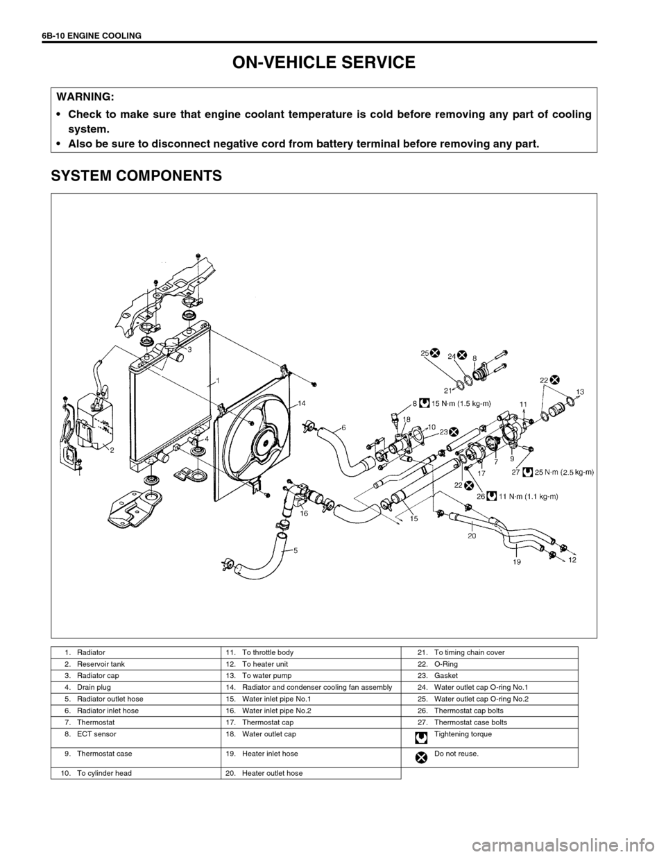
SYSTEM COMPONENTS
WARNING:
Check to make sure that engine coolant temperature is cold before removing any part of cooling
system.
Also be sure to disconnect negative cord from battery terminal before removing any part.
1. Radiator 11. To throttle body 21. To timing chain cover
2. Reservoir tank 12. To heater unit 22. O-Ring
3. Radiator cap 13. To water pump 23. Gasket
4. Drain plug 14. Radiator and condenser cooling fan assembly 24. Water outlet cap O-ring No.1
5. Radiator outlet hose 15. Water inlet pipe No.1 25. Water outlet cap O-ring No.2
6. Radiator inlet hose 16. Water inlet pipe No.2 26. Thermostat cap bolts
7. Thermostat 17. Thermostat cap 27. Thermostat case bolts
8. ECT sensor 18. Water outlet cap Tightening torque
9. Thermostat case 19. Heater inlet hose Do not reuse.
10. To cylinder head 20. Heater outlet hose
Page 602 of 698

ENGINE COOLING 6B-13
Check thermostatic movement of wax pellet as follows :
a) Immerse thermostat (1) in water, and heat water gradually.
b) Check that valve starts to open at specific temperature.
Temperature at which valve begins to open
: 80 – 84°C (176 – 183°F)
Temperature at which valve become fully open
: 95 – 97°C (203°F)
Valve lift
: More than 8 mm at 95°C (203°F)
If valve starts to open at a temperature substantially below or
above specific temperature, thermostat unit should be replaced
with a new one. Such a unit, if reused, will bring about overcool-
ing or overheating tendency.
INSTALLATION
Reverse removal procedure for installation noting the following
points.
When positioning thermostat (1) on thermostat case (2), be
sure to position it so that air bleed valve (3) comes at posi-
tion as shown in figure.
Use new O-rings when installing.
Adjust water pump belt tension referring to WATER PUMP/
GENERATOR DRIVE BELT TENSION INSPECTION AND
ADJUSTMENT in this section.
Adjust A/C compressor belt tension (if equipped) referring to
Section 1B.
Refill cooling system with proper coolant referring to “COOL-
ING SYSTEM REFILL”.
Verify that there is no coolant leakage at each connection.
2. Thermometer
3. Heater