temperature SUZUKI SWIFT 2000 1.G RG413 Service Repair Manual
[x] Cancel search | Manufacturer: SUZUKI, Model Year: 2000, Model line: SWIFT, Model: SUZUKI SWIFT 2000 1.GPages: 698, PDF Size: 16.01 MB
Page 622 of 698
ENGINE AND EMISSION CONTROL SYSTEM 6E1-1
6F1
6F2
6G
6H
6E1
7A
7A1
7B1
7C1
7D
7E
7F
8A
8B
8C
8D
8E
9
10
10A
10B
SECTION 6E1
ENGINE AND EMISSION CONTROL SYSTEM
CONTENTS
GENERAL DESCRIPTION ............................ 6E1-2
AIR INTAKE SYSTEM ............................... 6E1-5
FUEL DELIVERY SYSTEM ....................... 6E1-6
FUEL PUMP ........................................... 6E1-6
ELECTRONIC CONTROL SYSTEM .......... 6E1-7
ENGINE & EMISSION CONTROL
INPUT/OUTPUT TABLE ........................ 6E1-8
ECM INPUT/OUTPUT CIRCUIT
DIAGRAM............................................... 6E1-9
ECM TERMINAL ARRANGEMENT
TABLE .................................................. 6E1-13
ON-VEHICLE SERVICE .............................. 6E1-15
ACCELERATOR CABLE
ADJUSTMENT ..................................... 6E1-15
IDLE SPEED/IDLE AIR CONTROL
(IAC) DUTY INSPECTION ................... 6E1-15
IDLE MIXTURE INSPECTION /
ADJUSTMENT (VEHICLE WITHOUT
HEATED OXYGEN SENSOR) ............. 6E1-17
AIR INTAKE SYSTEM ............................. 6E1-18
THROTTLE BODY ............................... 6E1-18IDLE AIR CONTROL VALVE (IAC
VALVE) ................................................ 6E1-20
FUEL DELIVERY SYSTEM ..................... 6E1-21
FUEL PRESSURE INSPECTION ........ 6E1-21
FUEL PUMP WITH PRESSURE
REGULATOR ....................................... 6E1-22
FUEL INJECTOR ................................. 6E1-23
ELECTRONIC CONTROL SYSTEM ....... 6E1-27
ENGINE CONTROL MODULE
(ECM) ................................................... 6E1-27
MANIFOLD ABSOLUTE PRESSURE
SENSOR (MAP SENSOR)................... 6E1-27
THROTTLE POSITION SENSOR (TP
SENSOR) ............................................. 6E1-28
INTAKE AIR TEMPERATURE
SENSOR (IAT SENSOR) ..................... 6E1-29
ENGINE COOLANT TEMPERATURE
SENSOR (ECT SENSOR) ................... 6E1-30
HEATED OXYGEN SENSOR (HO2S-1
AND HO2S-2) ...................................... 6E1-31
CAMSHAFT POSITION SENSOR ....... 6E1-32 WARNING:
For vehicles equipped with Supplemental Restraint (Air Bag) System :
Service on and around the air bag system components or wiring must be performed only by an
authorized SUZUKI dealer. Refer to “Air Bag System Components and Wiring Location View” under
“General Description” in air bag system section in order to confirm whether you are performing ser-
vice on or near the air bag system components or wiring. Please observe all WARNINGS and “Ser-
vice Precautions” under “On-Vehicle Service” in air bag system section before performing service
on or around the air bag system components or wiring. Failure to follow WARNINGS could result in
unintentional activation of the system or could render the system inoperative. Either of these two
conditions may result in severe injury.
Technical service work must be started at least 90 seconds after the ignition switch is turned to the
“LOCK” position and the negative cable is disconnected from the battery. Otherwise, the system
may be activated by reserve energy in the Sensing and Diagnostic Module (SDM).
NOTE:
Whether the following system (parts) are used in the particular vehicle or not depends on vehicle
specifications. Be sure to bear this in mind when performing service work.
EGR valve
Heated oxygen sensor(s) or CO adjusting resistor
Three way catalytic converter
Immobilizer indicator lamp
Knock sensor
Page 637 of 698
6E1-16 ENGINE AND EMISSION CONTROL SYSTEM
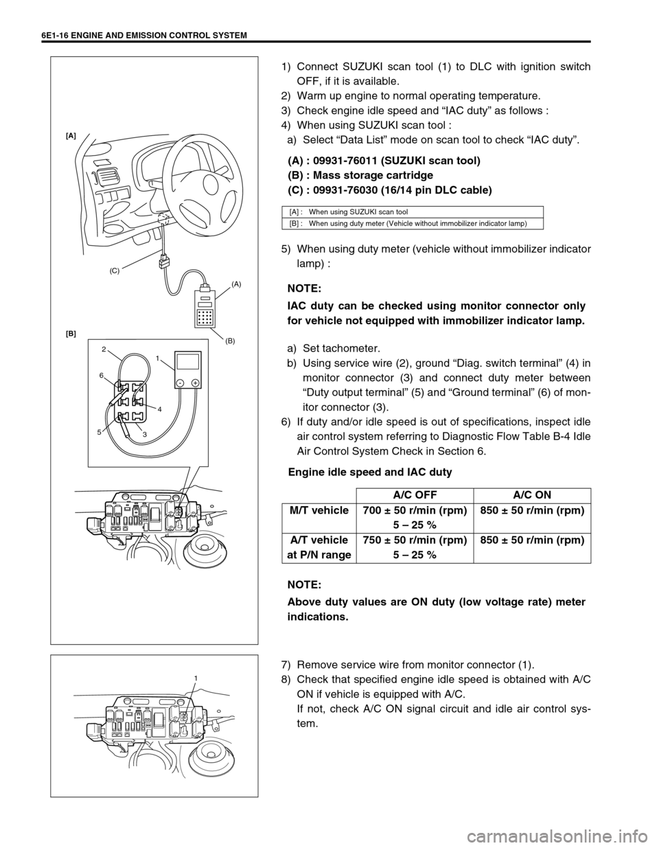
1) Connect SUZUKI scan tool (1) to DLC with ignition switch
OFF, if it is available.
2) Warm up engine to normal operating temperature.
3) Check engine idle speed and “IAC duty” as follows :
4) When using SUZUKI scan tool :
a) Select “Data List” mode on scan tool to check “IAC duty”.
(A) : 09931-76011 (SUZUKI scan tool)
(B) : Mass storage cartridge
(C) : 09931-76030 (16/14 pin DLC cable)
5) When using duty meter (vehicle without immobilizer indicator
lamp) :
a) Set tachometer.
b) Using service wire (2), ground “Diag. switch terminal” (4) in
monitor connector (3) and connect duty meter between
“Duty output terminal” (5) and “Ground terminal” (6) of mon-
itor connector (3).
6) If duty and/or idle speed is out of specifications, inspect idle
air control system referring to Diagnostic Flow Table B-4 Idle
Air Control System Check in Section 6.
Engine idle speed and IAC duty
7) Remove service wire from monitor connector (1).
8) Check that specified engine idle speed is obtained with A/C
ON if vehicle is equipped with A/C.
If not, check A/C ON signal circuit and idle air control sys-
tem.
[A] : When using SUZUKI scan tool
[B] : When using duty meter (Vehicle without immobilizer indicator lamp)
NOTE:
IAC duty can be checked using monitor connector only
for vehicle not equipped with immobilizer indicator lamp.
A/C OFF A/C ON
M/T vehicle 700 ± 50 r/min (rpm)
5 – 25 %850 ± 50 r/min (rpm)
A/T vehicle
at P/N range750 ± 50 r/min (rpm)
5 – 25 %850 ± 50 r/min (rpm)
NOTE:
Above duty values are ON duty (low voltage rate) meter
indications.
(C)
(A)
(B)
1 2
6
54
3-+
[A]
[B]
1
Page 650 of 698

ENGINE AND EMISSION CONTROL SYSTEM 6E1-29
INTAKE AIR TEMPERATURE SENSOR (IAT SENSOR)
REMOVAL
1) Disconnect battery negative cable at battery.
2) Disconnect coupler (1) from IAT sensor.
3) Remove IAT sensor from air cleaner case (2).
INSPECTION
Immerse temperature sensing part of IAT sensor in water (or ice)
and measure resistance between sensor terminals while heating
water gradually.
If measured resistance does not show such characteristic as
shown in left figure, replace IAT sensor.
INSTALLATION
Reverse removal procedure noting the following.
Clean mating surfaces of IAT sensor and air cleaner case.
Connect IAT sensor connector (1) securely.
1
2
1
Page 651 of 698
6E1-30 ENGINE AND EMISSION CONTROL SYSTEM
ENGINE COOLANT TEMPERATURE SENSOR (ECT
SENSOR)
REMOVAL
1) Disconnect battery negative cable at battery.
2) Drain coolant referring to Section 6B.
3) Remove air intake pipe.
4) Disconnect connector from ECT sensor.
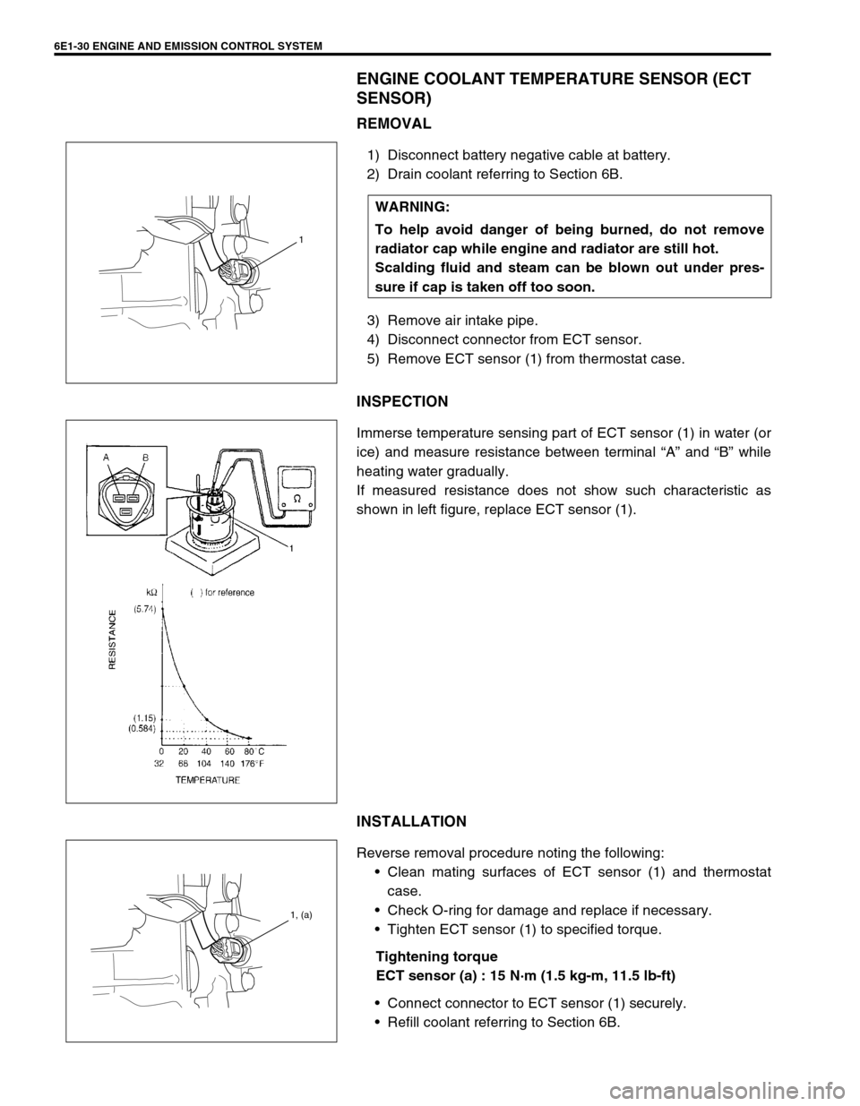
5) Remove ECT sensor (1) from thermostat case.
INSPECTION
Immerse temperature sensing part of ECT sensor (1) in water (or
ice) and measure resistance between terminal “A” and “B” while
heating water gradually.
If measured resistance does not show such characteristic as
shown in left figure, replace ECT sensor (1).
INSTALLATION
Reverse removal procedure noting the following:
Clean mating surfaces of ECT sensor (1) and thermostat
case.
Check O-ring for damage and replace if necessary.
Tighten ECT sensor (1) to specified torque.
Tightening torque
ECT sensor (a) : 15 N·m (1.5 kg-m, 11.5 lb-ft)
Connect connector to ECT sensor (1) securely.
Refill coolant referring to Section 6B. WARNING:
To help avoid danger of being burned, do not remove
radiator cap while engine and radiator are still hot.
Scalding fluid and steam can be blown out under pres-
sure if cap is taken off too soon.
1
1, (a)
Page 652 of 698

ENGINE AND EMISSION CONTROL SYSTEM 6E1-31
HEATED OXYGEN SENSOR (HO2S-1 AND HO2S-2)
OXYGEN SENSOR HEATER INSPECTION
1) Disconnect sensor connector.
2) Using ohmmeter, measure resistance between terminals
“V
B” and “GND” of sensor connector.
If found faulty, replace oxygen sensor.
Resistance of oxygen sensor heater
HO2S-1 : 5.0 – 6.4
Ω at 20°C (68°F)
HO2S-2 : 11.7 – 14.3
Ω at 20°C (68°F)
3) Connect sensor connector securely.
REMOVAL
1) Disconnect negative cable at battery.
2) For HO2S-1, disconnect connector of heated oxygen sensor
and release its wire harness from clamps, then remove front
bumper and heat insulator panel.
3) For HO2S-2, disconnect connector of heated oxygen sensor
and release its wire harness from clamp and hoist vehicle.
4) Remove heated oxygen sensor (1) from exhaust manifold or
exhaust pipe.
INSTALLATION
Reverse removal procedure noting the following.
Tighten heated oxygen sensor (1) to specified torque.
Tightening torque
Heated oxygen sensor (a) : 45 N·m (4.5 kg-m, 32.5 lb-ft)
Connect connector of heated oxygen sensor (1) and clamp
wire harness securely.
After installing heated oxygen sensor (1), start engine and
check that no exhaust gas leakage exists. NOTE:
Temperature of sensor affects resistance value largely.
Make sure that sensor heater is at correct temperature.
1. Viewed from terminal side
WARNING:
To avoid danger of being burned, do not touch exhaust
system when system is hot. Oxygen sensor removal
should be performed when system is cool.
[A] : HO2S-1
[B] : HO2S-2
Page 655 of 698

6E1-34 ENGINE AND EMISSION CONTROL SYSTEM
FUEL CUT OPERATION
INSPECTION
1) Warm up engine to normal operating temperature.
2) While listening to sound of injector (1) by using sound scope
(2) or such, increase engine speed to higher than 3,000 r/
min.
3) Check to make sure that sound to indicate operation of injec-
tor stops when throttle valve is closed instantly and it is
heard again when engine speed is reduced to less than
about 2,000 r/min.
RADIATOR FAN CONTROL SYSTEM
SYSTEM INSPECTION
Check system for operation referring to Flow Table B-7 in Section
6.
If radiator fan fails to operate properly, check relay, radiator fan
and electrical circuit.
RADIATOR FAN RELAY NO. 2 AND NO.3
INSPECTION
1) Disconnect negative cable at battery.
2) Remove relay(s) from connector(s).NOTE:
Before inspection, check to make sure that gear shift
lever is in neutral position (with A/T model, selector lever
in “P” range), A/C is OFF and that parking brake lever is
pulled all the way up.
WARNING:
Keep hands, tools, and clothing away from engine cool-
ing fan to help prevent personal injury. This fan is electric
and can come on whether or not the engine is running.
The fan can start automatically in response to the ECT
sensor with the ignition switch in the “ON” position.
1. Radiator fan relay No. 2
2. Radiator fan relay No. 3
1
2
Page 659 of 698
6E1-38 ENGINE AND EMISSION CONTROL SYSTEM
3) Connect purge hose to EVAP canister and warm up engine
to normal operating temperature.
4) Disconnect purge hose from EVAP canister.
5) Also check that vacuum is felt when engine is running at idle
speed.
If check result is not satisfactory, check vacuum passage,
hoses, EVAP canister purge valve, wire harness and ECM.
VACUUM PASSAGE INSPECTION
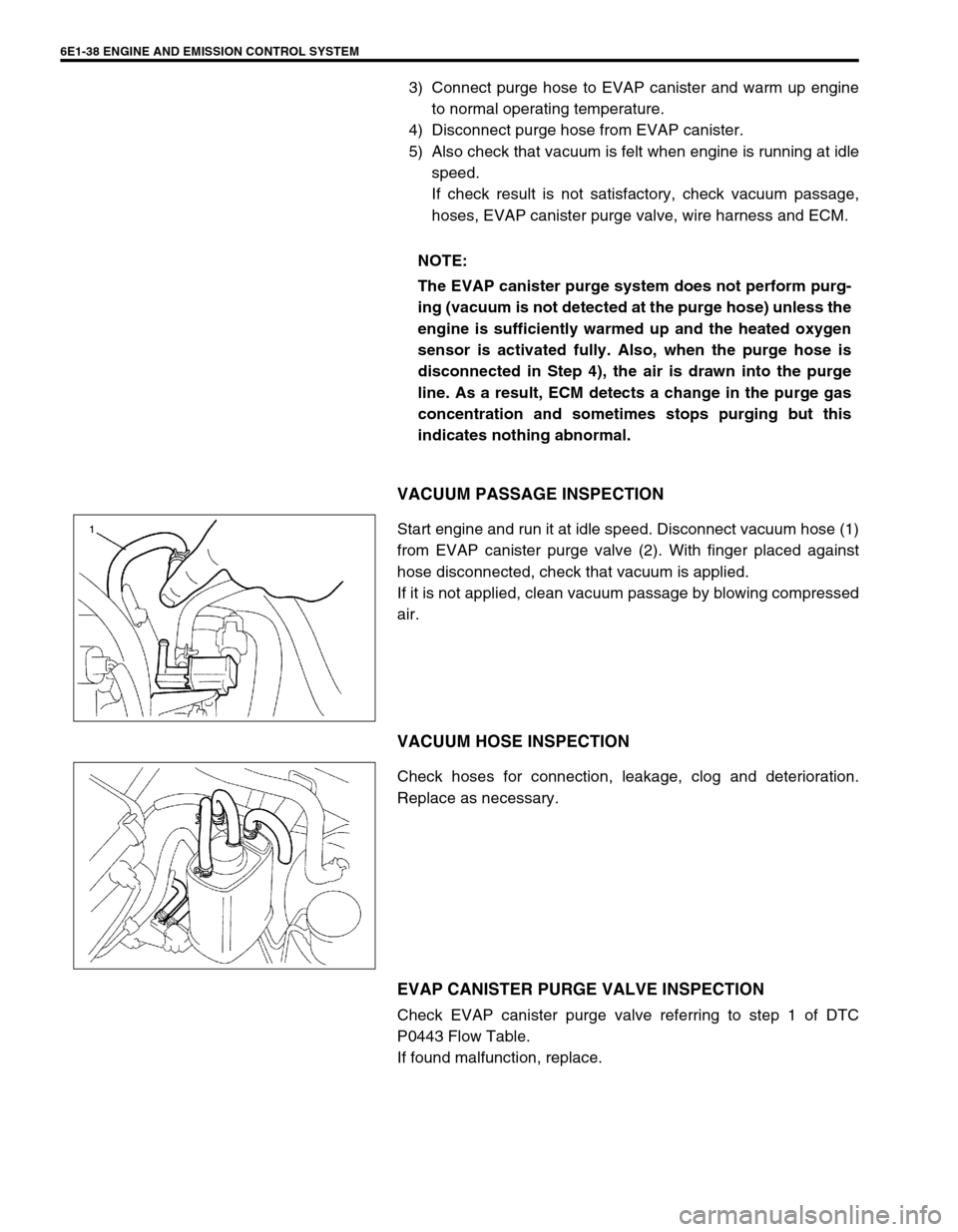
Start engine and run it at idle speed. Disconnect vacuum hose (1)
from EVAP canister purge valve (2). With finger placed against
hose disconnected, check that vacuum is applied.
If it is not applied, clean vacuum passage by blowing compressed
air.
VACUUM HOSE INSPECTION
Check hoses for connection, leakage, clog and deterioration.
Replace as necessary.
EVAP CANISTER PURGE VALVE INSPECTION
Check EVAP canister purge valve referring to step 1 of DTC
P0443 Flow Table.
If found malfunction, replace.NOTE:
The EVAP canister purge system does not perform purg-
ing (vacuum is not detected at the purge hose) unless the
engine is sufficiently warmed up and the heated oxygen
sensor is activated fully. Also, when the purge hose is
disconnected in Step 4), the air is drawn into the purge
line. As a result, ECM detects a change in the purge gas
concentration and sometimes stops purging but this
indicates nothing abnormal.
Page 682 of 698
6H-2 CHARGING SYSTEM
GENERAL DESCRIPTION
BATTERY
The battery has three major functions in the electrical system.
It is a source of electrical energy for cranking the engine.
It acts as a voltage stabilizer for the electrical system.
It can, for a limited time, provide energy when the electrical load exceeds the output of the generator.
CARRIER AND HOLD-DOWN
The battery carrier should be in good condition so that it will support the battery securely and keep it level.
Before installing the battery, the battery carrier and hold-down clamp should be clean and free from corrosion
and make certain there are no parts in carrier.
To prevent the battery from shaking in its carrier, the hold-down bolts should be tight enough but not over-tight-
ened.
ELECTROLYTE FREEZING
The freezing point of electrolyte depends on its specific gravity. Since freezing may ruin a battery, it should be
protected against freezing by keeping it in a fully charged condition. If a battery is frozen accidentally, it should
not be charged until it is warmed.
SULFATION
If the battery is allowed to stand for a long period in discharged condition, the lead sulfate becomes converted
into a hard, crystalline substance, which will not easily turn back to the active material again during the subse-
quent recharging. “Sulfation” means the result as well as the process of that reaction. Such a battery can be
revived by very slow charging and may be restored to usable condition but its capacity is lower than before.
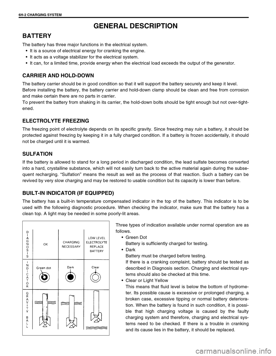
BUILT-IN INDICATOR (IF EQUIPPED)
The battery has a built-in temperature compensated indicator in the top of the battery. This indicator is to be
used with the following diagnostic procedure. When checking the indicator, make sure that the battery has a
clean top. A light may be needed in some poorly-lit areas.
Three types of indication available under normal operation are as
follows.
Green Dot
Battery is sufficiently charged for testing.
Dark
Battery must be charged before testing.
If there is a cranking complaint, battery should be tested as
described in Diagnosis section. Charging and electrical sys-
tems should also be checked at this time.
Clear or Light Yellow
This means that fluid level is below the bottom of hydrome-
ter. Its possible cause is excessive or prolonged charging, a
broken case, excessive tipping or normal battery deteriora-
tion. When the battery is found in such condition, it is possi-
ble that high charging voltage is caused by the faulty
charging system and therefore, charging and electrical sys-
tems need to be checked. If there is a trouble in cranking
and its cause lies in the battery, it should be replaced.
Page 683 of 698

CHARGING SYSTEM 6H-3
CARE OF BATTERY
1) The battery is a very reliable component, but needs periodical attentions.
Keep the battery carrier clean
Prevent rust formation on the terminal posts
Keep the electrolyte up to the upper level uniformly in all cells.
When keeping battery on vehicle over a long period of time, follow instructions given below.
–Weekly, start the engine and run it until it reaches normal operating temperature with engine speed of
2000 to 3000 rpm. Make sure all electric switches are off before storing the vehicle.
–Recharge the battery twice a month to prevent it from discharging excessively. This is especially impor-
tant when ambient temperature is low.
The battery discharges even when it is not used, while vehicles are being stored. Battery electrolyte can
freeze and battery case can crack at cold ambient condition if battery is not properly charged.
2) Keep the battery cable connections clean.
The cable connections, particularly at the positive (+) terminal post, tend to become corroded. The product
of corrosion, or rust, on the mating faces of conductors resists the flow of current.
Clean the terminals and fittings periodically to ensure good metal-to-metal contact, and grease the connec-
tions after each cleaning to protect them against rusting.
3) Be always in the know as to the state of charge of the battery. The simplest way to tell the state of charge is
to carry out a hydrometer test. The hydrometer is an instrument for measuring the specific gravity (S.G.) of
the battery electrolyte. The S.G. of the electrolyte is indicative of the state of charge. Refer to “DIAGNOSIS”
of BATTERY in this section. WARNING:
Never expose battery to open flame or electric spark because of battery generate gas which is flam-
mable and explosive.
Do not allow battery fluid to contact eyes, skin, fabrics, or painted surfaces as fluid is a corrosive
acid. Flush any contacted area with water immediately and thoroughly.
Batteries should always be kept out of reach of children.
Page 685 of 698
CHARGING SYSTEM 6H-5
DIAGNOSIS
BATTERY
VISUAL INSPECTION
Check for obvious damage, such as cracked or broken case or cover, that could permit loss of electrolyte. If
obvious damage is noted, replace battery. Determine cause of damage and correct as needed.
HYDROMETER TEST
The direct method of checking the battery for state of charge is to
carry out a high rate discharge test, which involves a special pre-
cise voltmeter and an expensive instrument used in the service
shops, but not recommendable to the user of the vehicle.
At 20 °C of battery temperature (electrolyte temperature):
The battery is in FULLY CHARGED STATE if the electrolyte
S.G. is 1.280.
The battery is in HALF CHARGED STATE if the S.G. is
1.220.
The battery is in NEARLY DISCHARGED STATE if the S.G.
is 1.150 and is in danger of freezing.
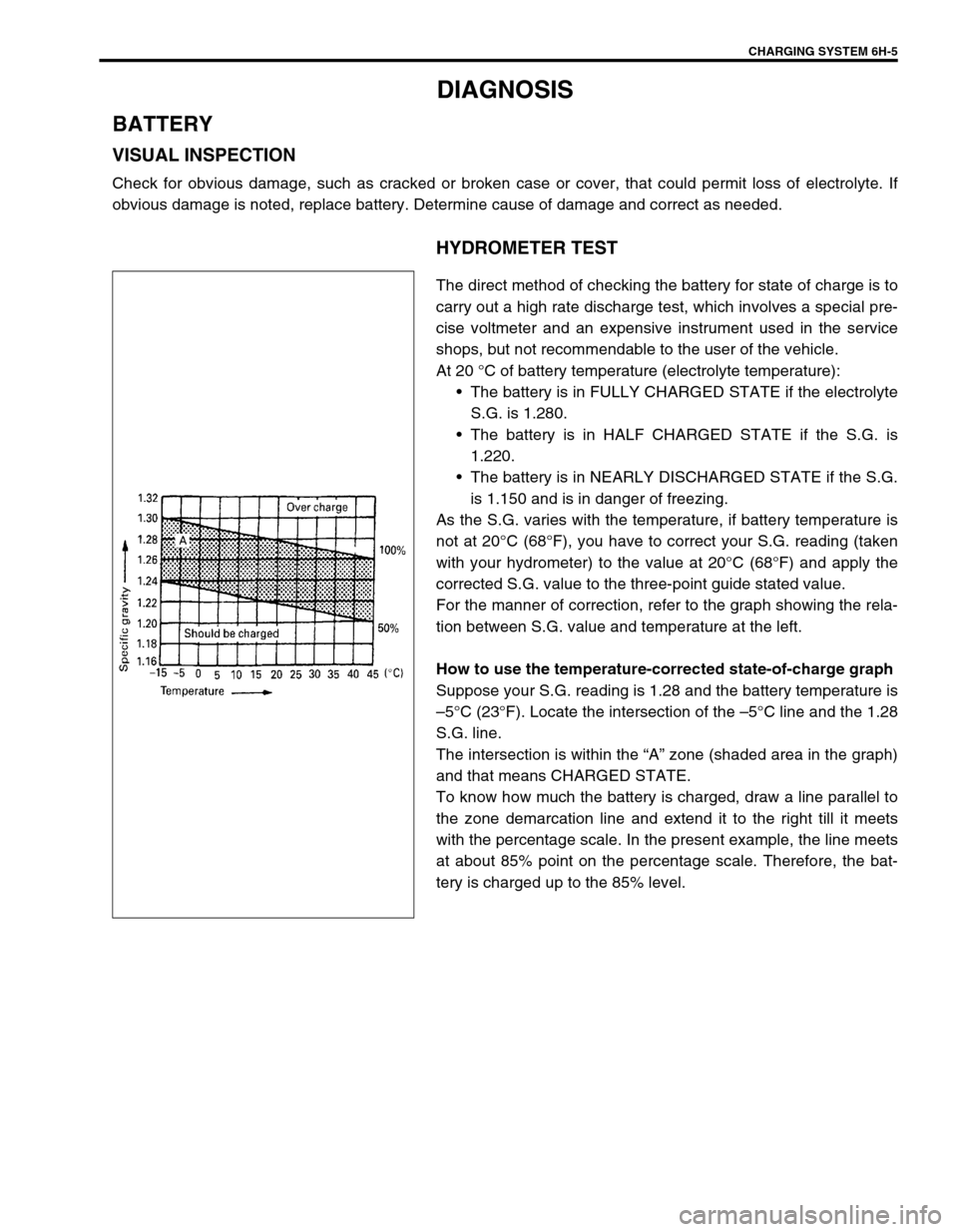
As the S.G. varies with the temperature, if battery temperature is
not at 20°C (68°F), you have to correct your S.G. reading (taken
with your hydrometer) to the value at 20°C (68°F) and apply the
corrected S.G. value to the three-point guide stated value.
For the manner of correction, refer to the graph showing the rela-
tion between S.G. value and temperature at the left.
How to use the temperature-corrected state-of-charge graph
Suppose your S.G. reading is 1.28 and the battery temperature is
–5°C (23°F). Locate the intersection of the –5°C line and the 1.28
S.G. line.
The intersection is within the “A” zone (shaded area in the graph)
and that means CHARGED STATE.
To know how much the battery is charged, draw a line parallel to
the zone demarcation line and extend it to the right till it meets
with the percentage scale. In the present example, the line meets
at about 85% point on the percentage scale. Therefore, the bat-
tery is charged up to the 85% level.