valve SUZUKI SWIFT 2000 1.G RG413 Service Owner's Manual
[x] Cancel search | Manufacturer: SUZUKI, Model Year: 2000, Model line: SWIFT, Model: SUZUKI SWIFT 2000 1.GPages: 698, PDF Size: 16.01 MB
Page 97 of 698
1B-32 AIR CONDITIONING (OPTIONAL)
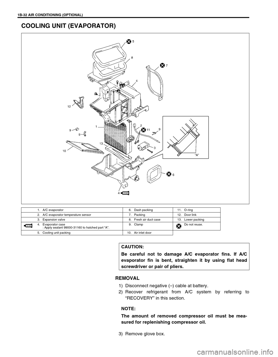
COOLING UNIT (EVAPORATOR)
REMOVAL
1) Disconnect negative (–) cable at battery.
2) Recover refrigerant from A/C system by referring to
“RECOVERY” in this section.
3) Remove glove box.
1. A/C evaporator 6. Dash packing 11. O-ring
2. A/C evaporator temperature sensor 7. Packing 12. Door link
3. Expansion valve 8. Fresh air duct case 13. Lower packing
4. Evaporator case
: Apply sealant 99000-31160 to hatched part “A”.9. Clamp Do not reuse.
5. Cooling unit packing 10. Air inlet door
CAUTION:
Be careful not to damage A/C evaporator fins. If A/C
evaporator fin is bent, straighten it by using flat head
screwdriver or pair of pliers.
NOTE:
The amount of removed compressor oil must be mea-
sured for replenishing compressor oil.
Page 99 of 698
1B-34 AIR CONDITIONING (OPTIONAL)
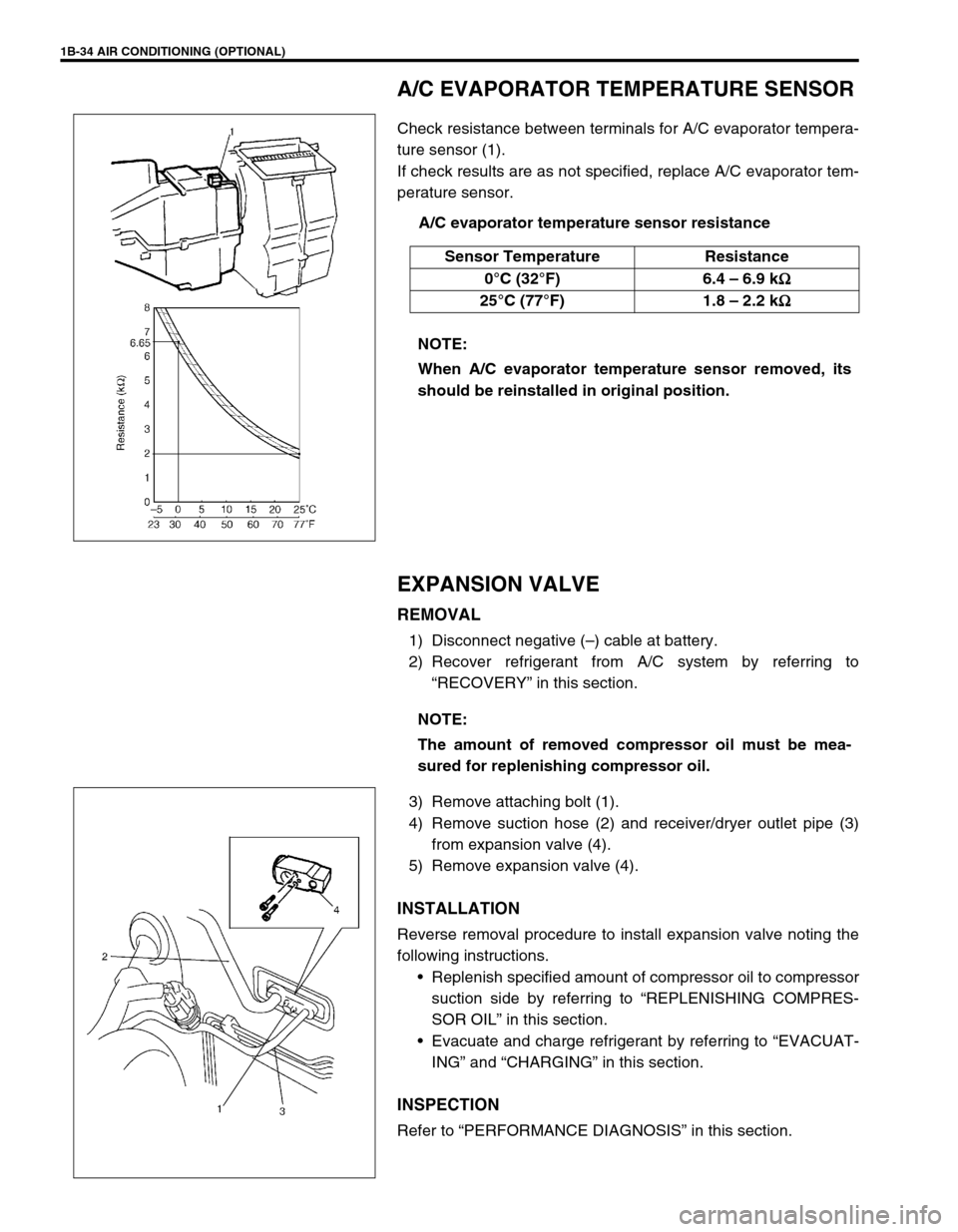
A/C EVAPORATOR TEMPERATURE SENSOR
Check resistance between terminals for A/C evaporator tempera-
ture sensor (1).
If check results are as not specified, replace A/C evaporator tem-
perature sensor.
A/C evaporator temperature sensor resistance
EXPANSION VALVE
REMOVAL
1) Disconnect negative (–) cable at battery.
2) Recover refrigerant from A/C system by referring to
“RECOVERY” in this section.
3) Remove attaching bolt (1).
4) Remove suction hose (2) and receiver/dryer outlet pipe (3)
from expansion valve (4).
5) Remove expansion valve (4).
INSTALLATION
Reverse removal procedure to install expansion valve noting the
following instructions.
Replenish specified amount of compressor oil to compressor
suction side by referring to “REPLENISHING COMPRES-
SOR OIL” in this section.
Evacuate and charge refrigerant by referring to “EVACUAT-
ING” and “CHARGING” in this section.
INSPECTION
Refer to “PERFORMANCE DIAGNOSIS” in this section. Sensor Temperature Resistance
0°C (32°F) 6.4 – 6.9 k
Ω
ΩΩ Ω
25°C (77°F) 1.8 – 2.2 k
Ω
ΩΩ Ω
NOTE:
When A/C evaporator temperature sensor removed, its
should be reinstalled in original position.
NOTE:
The amount of removed compressor oil must be mea-
sured for replenishing compressor oil.
Page 109 of 698
1B-44 AIR CONDITIONING (OPTIONAL)
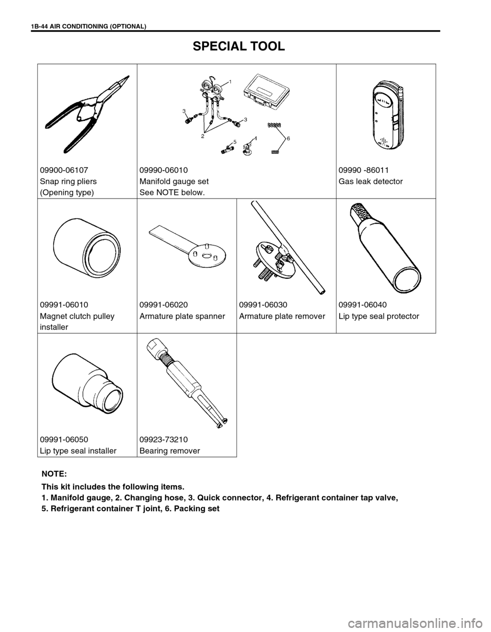
SPECIAL TOOL
09900-06107 09990-06010 09990 -86011
Snap ring pliers
(Opening type)Manifold gauge set
See NOTE below.Gas leak detector
09991-06010 09991-06020 09991-06030 09991-06040
Magnet clutch pulley
installerArmature plate spanner Armature plate remover Lip type seal protector
09991-06050 09923-73210
Lip type seal installer Bearing remover
NOTE:
This kit includes the following items.
1. Manifold gauge, 2. Changing hose, 3. Quick connector, 4. Refrigerant container tap valve,
5. Refrigerant container T joint, 6. Packing set
Page 253 of 698
3F-8 WHEELS AND TIRES
TIRE
MOUNTING AND DISMOUNTING
Use a tire changing machine to mount or dismount tires. Follow equipment manufacturer’s instructions. Do not
use hand tools or tire irons alone to change tires as they may damage tire beads or wheel rim.
Rim bead seats should be cleaned with a wire brush or coarse steel wool to remove lubricants, old rubber and
light rust. Before mounting or dismounting a tire, bead area should be well lubricated with approved tire lubri-
cant.
After mounting, inflate to specified pressure shown on tire placard so that beads are completely seated.
Install valve core and inflate to proper pressure.
REPAIR
There are many different materials and techniques on the market to repair tires. As not all of these work on all
types of tires, tire manufacturers have published detailed instructions on how and when to repair tires. These
instructions can be obtained from each tire manufacturer.WARNING:
Do not stand over tire when inflating. Bead may break when bead snaps over rim’s safety hump and
cause serious personal injury.
Do not exceed specified pressure when inflating. If specified pressure will not seat beads, deflate, re-
lubricate and reinflate.
Over inflation may cause bead to break and cause serious personal injury.
Page 274 of 698
BRAKES 5-1
6F1
6F2
6G
6H
6K
7A
7A1
7B1
7C1
7D
7E
7F
8A
8B
8C
5
9
10
10A
10B
SECTION 5
BRAKES
CONTENTS
GENERAL DESCRIPTION ................................ 5-2
DIAGNOSIS ....................................................... 5-4
ROAD TESTING BRAKES ............................. 5-4
BRAKE FLUID LEAKS ................................... 5-4
SUBSTANDARD OR CONTAMINATED
BRAKE FLUID ................................................ 5-4
DIAGNOSIS TABLE ....................................... 5-5
BRAKE PEDAL FREE HEIGHT
ADJUSTMENT ............................................... 5-8
BRAKE PEDAL PLAY INSPECTION ............. 5-8
STOP LIGHT SWITCH ADJUSTMENT.......... 5-8
EXCESSIVE PEDAL TRAVEL
INSPECTION ................................................. 5-9
FRONT BRAKE PAD INSPECTION .............. 5-9
BRAKE DISC INSPECTION........................... 5-9
PARKING BRAKE INSPECTION AND
ADJUSTMENT ............................................. 5-10
BOOSTER OPERATION INSPECTION....... 5-11
FLUID PRESSURE TEST (IF EQUIPPED
WITH LSPV) ................................................ 5-12
MASTER CYLINDER AND BRAKE FLUID
LEVEL INSPECTION ................................... 5-14
BRAKE HOSE AND PIPE INSPECTION ..... 5-15
HOSE ....................................................... 5-15
PIPE ......................................................... 5-15
ON-VEHICLE SERVICE .................................. 5-15AIR BLEEDING OF BRAKE SYSTEM ......... 5-15
FRONT BRAKE ........................................... 5-17
BRAKE PAD............................................. 5-17
CALIPER ASSEMBLY ............................. 5-19
BRAKE DISC ........................................... 5-23
REAR BRAKE .............................................. 5-25
BRAKE DRUM ......................................... 5-26
BRAKE SHOE .......................................... 5-29
WHEEL CYLINDER ................................. 5-30
BRAKE BACK PLATE (FOR 2WD
VEHICLE)................................................. 5-31
BRAKE BACK PLATE (FOR 4WD
VEHICLE)................................................. 5-33
MASTER CYLINDER ................................... 5-33
MASTER CYLINDER RESERVOIR ......... 5-33
MASTER CYLINDER ASSEMBLY........... 5-34
BRAKE BOOSTER ...................................... 5-38
BRAKE HOSE/PIPE .................................... 5-41
FRONT BRAKE HOSE/PIPE ................... 5-41
REAR BRAKE HOSE/PIPE...................... 5-44
PARKING BRAKE CABLE ........................... 5-46
LSPV (LOAD SENSING PROPORTIONING
VALVE) ASSEMBLY (IF EQUIPPED).......... 5-48
REQUIRED SERVICE MATERIAL.................. 5-50
SPECIAL TOOL .............................................. 5-50
NOTE:
All front fasteners are important attaching parts in that they could affect the performance of vital parts
and systems, and/or could result in major repair expense. They must be replaced with one of same
part number or with an equivalent part if replacement becomes necessary. Do not use a replacement
part of lesser quality or substitute design. Torque values must be used as specified during reassem-
bly to assure proper retention of all parts. There is to be no welding as it may result in extensive dam-
age and weakening of the metal.
Page 275 of 698
5-2 BRAKES
GENERAL DESCRIPTION
When the foot brake pedal is depressed, hydraulic pressure is developed in the master cylinder to actuate pis-
tons (two in front and four in rear).
The master cylinder is a tandem master cylinder. Brake pipes are connected to the master cylinder and they
make two independent circuits. One connects front right & rear left brakes and the other connects front left &
rear right brakes.
The load sensing proportioning valve (LSPV) or the proportioning valve (P valve) is included in these circuits
between the master cylinder and the rear brake for the vehicle without ABS.
In this brake system, the disc brake type is used for the front wheel brake and a drum brake type (leading/trailing
shoes) for the rear brake.
The parking brake system is mechanical. It applies brake force to only rear wheels by means of the cable and
mechanical linkage system. The same brake shoes are used for both parking and foot brakes.
Page 276 of 698
![SUZUKI SWIFT 2000 1.G RG413 Service Owners Manual BRAKES 5-3
NOTE:
The figures shows left-hand steering vehicle.
[A] : For vehicle without ABS 3. Secondary side 7. LSPV (Load Sensing Proportioning valve)
[B] : For vehicle with ABS 4. Primary side 8. SUZUKI SWIFT 2000 1.G RG413 Service Owners Manual BRAKES 5-3
NOTE:
The figures shows left-hand steering vehicle.
[A] : For vehicle without ABS 3. Secondary side 7. LSPV (Load Sensing Proportioning valve)
[B] : For vehicle with ABS 4. Primary side 8.](/img/20/7606/w960_7606-275.png)
BRAKES 5-3
NOTE:
The figures shows left-hand steering vehicle.
[A] : For vehicle without ABS 3. Secondary side 7. LSPV (Load Sensing Proportioning valve)
[B] : For vehicle with ABS 4. Primary side 8. P (Proportioning) valve
1. Brake booster 5. 4-way joint A: Forward
2. Master cylinder 6. ABS hydraulic unit/control module assembly
Page 318 of 698
![SUZUKI SWIFT 2000 1.G RG413 Service Owners Manual BRAKES 5-45
T : Top side 1. 4 way joint [A] : with ABS
F : Front side 2. LSPV assembly [B] : without ABS
R : Right side 3. P valve [C] : with LSPV
L : Left side 4. Rear brake hose Tightening torque SUZUKI SWIFT 2000 1.G RG413 Service Owners Manual BRAKES 5-45
T : Top side 1. 4 way joint [A] : with ABS
F : Front side 2. LSPV assembly [B] : without ABS
R : Right side 3. P valve [C] : with LSPV
L : Left side 4. Rear brake hose Tightening torque](/img/20/7606/w960_7606-317.png)
BRAKES 5-45
T : Top side 1. 4 way joint [A] : with ABS
F : Front side 2. LSPV assembly [B] : without ABS
R : Right side 3. P valve [C] : with LSPV
L : Left side 4. Rear brake hose Tightening torque
B : View B a-g: Clamp
Page 321 of 698
5-48 BRAKES
LSPV (LOAD SENSING PROPORTIONING VALVE) ASSEMBLY (IF EQUIPPED)
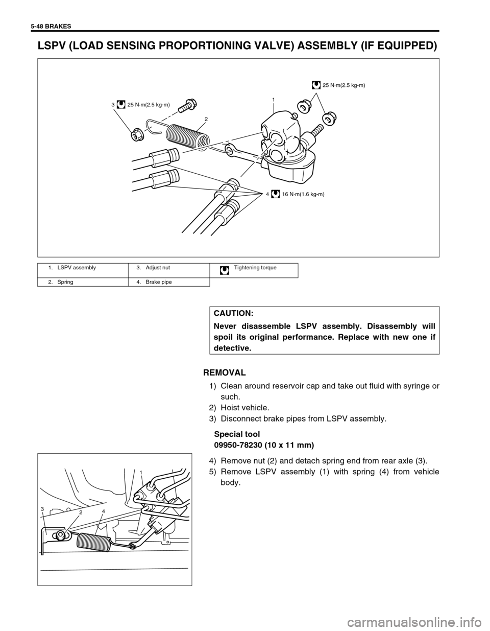
REMOVAL
1) Clean around reservoir cap and take out fluid with syringe or
such.
2) Hoist vehicle.
3) Disconnect brake pipes from LSPV assembly.
Special tool
09950-78230 (10 x 11 mm)
4) Remove nut (2) and detach spring end from rear axle (3).
5) Remove LSPV assembly (1) with spring (4) from vehicle
body.
1. LSPV assembly 3. Adjust nut Tightening torque
2. Spring 4. Brake pipe
CAUTION:
Never disassemble LSPV assembly. Disassembly will
spoil its original performance. Replace with new one if
detective.
3
21
25 N·m(2.5 kg-m)
4 16 N·m(1.6 kg-m)
25 N·m(2.5 kg-m)
3
24
1
Page 328 of 698
ANTILOCK BRAKE SYSTEM (ABS) 5E-3
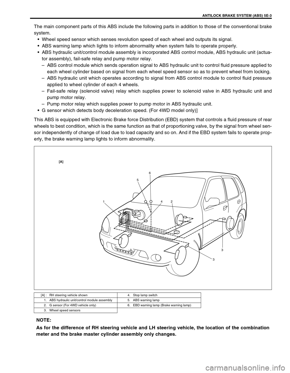
The main component parts of this ABS include the following parts in addition to those of the conventional brake
system.
Wheel speed sensor which senses revolution speed of each wheel and outputs its signal.
ABS warning lamp which lights to inform abnormality when system fails to operate properly.
ABS hydraulic unit/control module assembly is incorporated ABS control module, ABS hydraulic unit (actua-
tor assembly), fail-safe relay and pump motor relay.
–ABS control module which sends operation signal to ABS hydraulic unit to control fluid pressure applied to
each wheel cylinder based on signal from each wheel speed sensor so as to prevent wheel from locking.
–ABS hydraulic unit which operates according to signal from ABS control module to control fluid pressure
applied to wheel cylinder of each 4 wheels.
–Fail-safe relay (solenoid valve) relay which supplies power to solenoid valve in ABS hydraulic unit and
pump motor relay.
–Pump motor relay which supplies power to pump motor in ABS hydraulic unit.
G sensor which detects body deceleration speed. (For 4WD model only)]
This ABS is equipped with Electronic Brake force Distribution (EBD) system that controls a fluid pressure of rear
wheels to best condition, which is the same function as that of proportioning valve, by the signal from wheel sen-
sor independently of change of load due to load capacity and so on. And if the EBD system fails to operate prop-
erly, the brake warning lamp lights to inform abnormality.
[A] : RH steering vehicle shown 4. Stop lamp switch
1. ABS hydraulic unit/control module assembly 5. ABS warning lamp
2. G sensor (For 4WD vehicle only) 6. EBD warning lamp (Brake warning lamp)
3. Wheel speed sensors
156
2 4
33
[A]
NOTE:
As for the difference of RH steering vehicle and LH steering vehicle, the location of the combination
meter and the brake master cylinder assembly only changes.