valve SUZUKI SWIFT 2000 1.G RG413 Service Owner's Guide
[x] Cancel search | Manufacturer: SUZUKI, Model Year: 2000, Model line: SWIFT, Model: SUZUKI SWIFT 2000 1.GPages: 698, PDF Size: 16.01 MB
Page 332 of 698
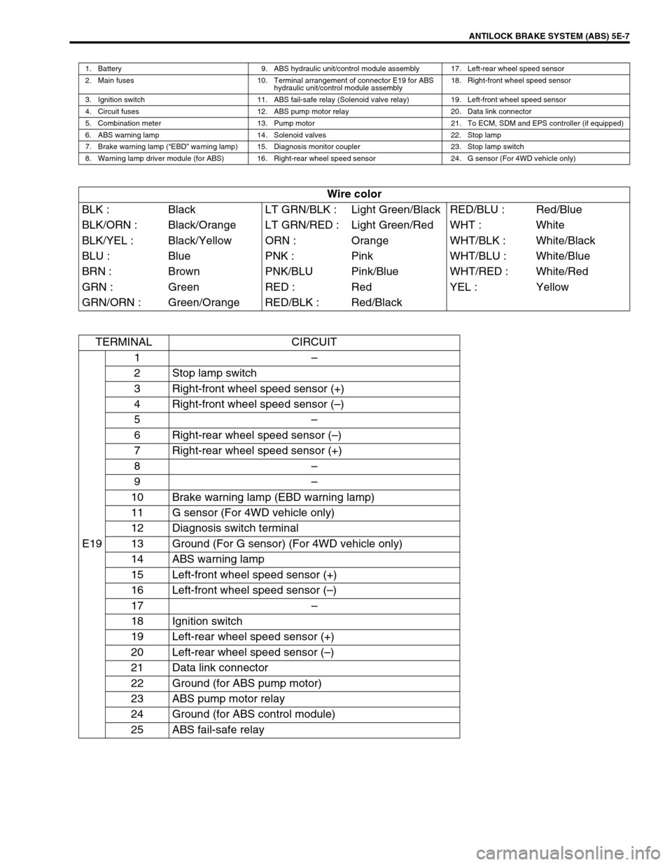
ANTILOCK BRAKE SYSTEM (ABS) 5E-7
1. Battery 9. ABS hydraulic unit/control module assembly 17. Left-rear wheel speed sensor
2. Main fuses 10. Terminal arrangement of connector E19 for ABS
hydraulic unit/control module assembly18. Right-front wheel speed sensor
3. Ignition switch 11. ABS fail-safe relay (Solenoid valve relay) 19. Left-front wheel speed sensor
4. Circuit fuses 12. ABS pump motor relay 20. Data link connector
5. Combination meter 13. Pump motor 21. To ECM, SDM and EPS controller (if equipped)
6. ABS warning lamp 14. Solenoid valves 22. Stop lamp
7. Brake warning lamp (“EBD” warning lamp) 15. Diagnosis monitor coupler 23. Stop lamp switch
8. Warning lamp driver module (for ABS) 16. Right-rear wheel speed sensor 24. G sensor (For 4WD vehicle only)
Wire color
BLK : Black LT GRN/BLK : Light Green/Black RED/BLU : Red/Blue
BLK/ORN : Black/Orange LT GRN/RED : Light Green/Red WHT : White
BLK/YEL : Black/Yellow ORN : Orange WHT/BLK : White/Black
BLU : Blue PNK : Pink WHT/BLU : White/Blue
BRN : Brown PNK/BLU Pink/Blue WHT/RED : White/Red
GRN : Green RED : Red YEL : Yellow
GRN/ORN : Green/Orange RED/BLK : Red/Black
TERMINAL CIRCUIT
E191–
2 Stop lamp switch
3 Right-front wheel speed sensor (+)
4 Right-front wheel speed sensor (–)
5–
6 Right-rear wheel speed sensor (–)
7 Right-rear wheel speed sensor (+)
8–
9–
10 Brake warning lamp (EBD warning lamp)
11 G sensor (For 4WD vehicle only)
12 Diagnosis switch terminal
13 Ground (For G sensor) (For 4WD vehicle only)
14 ABS warning lamp
15 Left-front wheel speed sensor (+)
16 Left-front wheel speed sensor (–)
17–
18 Ignition switch
19 Left-rear wheel speed sensor (+)
20 Left-rear wheel speed sensor (–)
21 Data link connector
22 Ground (for ABS pump motor)
23 ABS pump motor relay
24 Ground (for ABS control module)
25 ABS fail-safe relay
Page 346 of 698
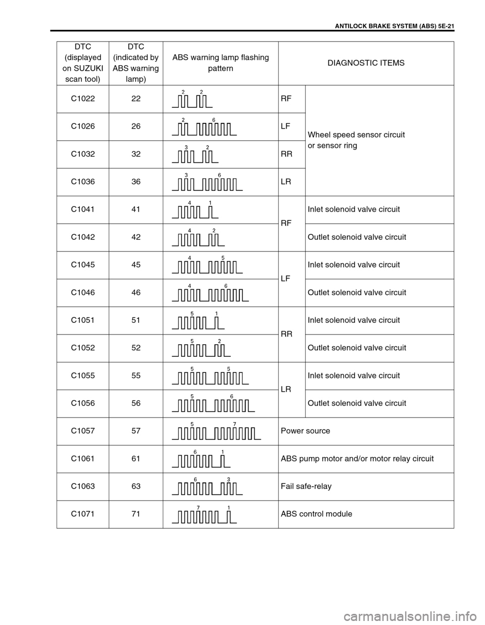
ANTILOCK BRAKE SYSTEM (ABS) 5E-21
C1022 22 RF
Wheel speed sensor circuit
or sensor ring C1026 26 LF
C1032 32 RR
C1036 36 LR
C1041 41
RFInlet solenoid valve circuit
C1042 42 Outlet solenoid valve circuit
C1045 45
LFInlet solenoid valve circuit
C1046 46 Outlet solenoid valve circuit
C1051 51
RRInlet solenoid valve circuit
C1052 52 Outlet solenoid valve circuit
C1055 55
LRInlet solenoid valve circuit
C1056 56 Outlet solenoid valve circuit
C1057 57 Power source
C1061 61 ABS pump motor and/or motor relay circuit
C1063 63 Fail safe-relay
C1071 71 ABS control moduleDTC
(displayed
on SUZUKI
scan tool)DTC
(indicated by
ABS warning
lamp)ABS warning lamp flashing
patternDIAGNOSTIC ITEMS
Page 351 of 698
5E-26 ANTILOCK BRAKE SYSTEM (ABS)
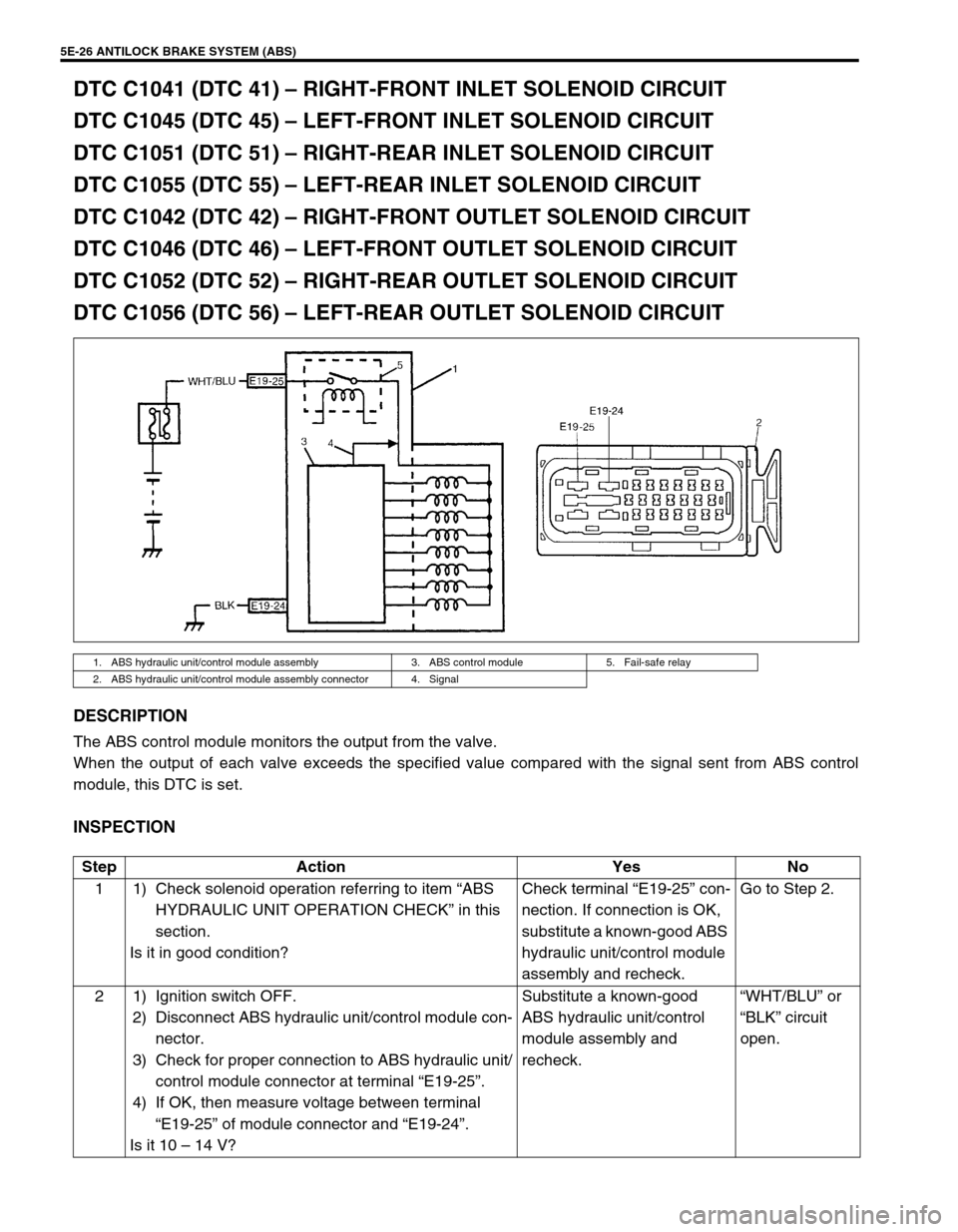
DTC C1041 (DTC 41) – RIGHT-FRONT INLET SOLENOID CIRCUIT
DTC C1045 (DTC 45) – LEFT-FRONT INLET SOLENOID CIRCUIT
DTC C1051 (DTC 51) – RIGHT-REAR INLET SOLENOID CIRCUIT
DTC C1055 (DTC 55) – LEFT-REAR INLET SOLENOID CIRCUIT
DTC C1042 (DTC 42) – RIGHT-FRONT OUTLET SOLENOID CIRCUIT
DTC C1046 (DTC 46) – LEFT-FRONT OUTLET SOLENOID CIRCUIT
DTC C1052 (DTC 52) – RIGHT-REAR OUTLET SOLENOID CIRCUIT
DTC C1056 (DTC 56) – LEFT-REAR OUTLET SOLENOID CIRCUIT
DESCRIPTION
The ABS control module monitors the output from the valve.
When the output of each valve exceeds the specified value compared with the signal sent from ABS control
module, this DTC is set.
INSPECTION
1. ABS hydraulic unit/control module assembly 3. ABS control module 5. Fail-safe relay
2. ABS hydraulic unit/control module assembly connector 4. Signal
Step Action Yes No
1 1) Check solenoid operation referring to item “ABS
HYDRAULIC UNIT OPERATION CHECK” in this
section.
Is it in good condition?Check terminal “E19-25” con-
nection. If connection is OK,
substitute a known-good ABS
hydraulic unit/control module
assembly and recheck.Go to Step 2.
2 1) Ignition switch OFF.
2) Disconnect ABS hydraulic unit/control module con-
nector.
3) Check for proper connection to ABS hydraulic unit/
control module connector at terminal “E19-25”.
4) If OK, then measure voltage between terminal
“E19-25” of module connector and “E19-24”.
Is it 10 – 14 V?Substitute a known-good
ABS hydraulic unit/control
module assembly and
recheck.“WHT/BLU” or
“BLK” circuit
open.
Page 354 of 698
ANTILOCK BRAKE SYSTEM (ABS) 5E-29
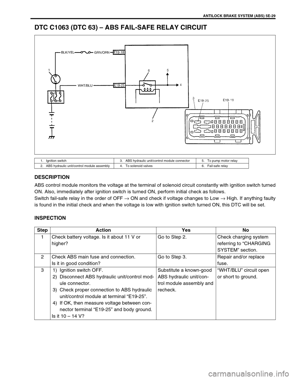
DTC C1063 (DTC 63) – ABS FAIL-SAFE RELAY CIRCUIT
DESCRIPTION
ABS control module monitors the voltage at the terminal of solenoid circuit constantly with ignition switch turned
ON. Also, immediately after ignition switch is turned ON, perform initial check as follows.
Switch fail-safe relay in the order of OFF → ON and check if voltage changes to Low → High. If anything faulty
is found in the initial check and when the voltage is low with ignition switch turned ON, this DTC will be set.
INSPECTION
1. Ignition switch 3. ABS hydraulic unit/control module connector 5. To pump motor relay
2. ABS hydraulic unit/control module assembly 4. To solenoid valves 6. Fail-safe relay
Step Action Yes No
1 Check battery voltage. Is it about 11 V or
higher?Go to Step 2. Check charging system
referring to “CHARGING
SYSTEM” section.
2 Check ABS main fuse and connection.
Is it in good condition?Go to Step 3. Repair and/or replace
fuse.
3 1) Ignition switch OFF.
2) Disconnect ABS hydraulic unit/control mod-
ule connector.
3) Check proper connection to ABS hydraulic
unit/control module at terminal “E19-25”.
4) If OK, then measure voltage between con-
nector terminal “E19-25” and body ground.
Is it 10 – 14 V?Substitute a known-good
ABS hydraulic unit/con-
trol module assembly and
recheck.“WHT/BLU” circuit open
or short to ground.
Page 370 of 698
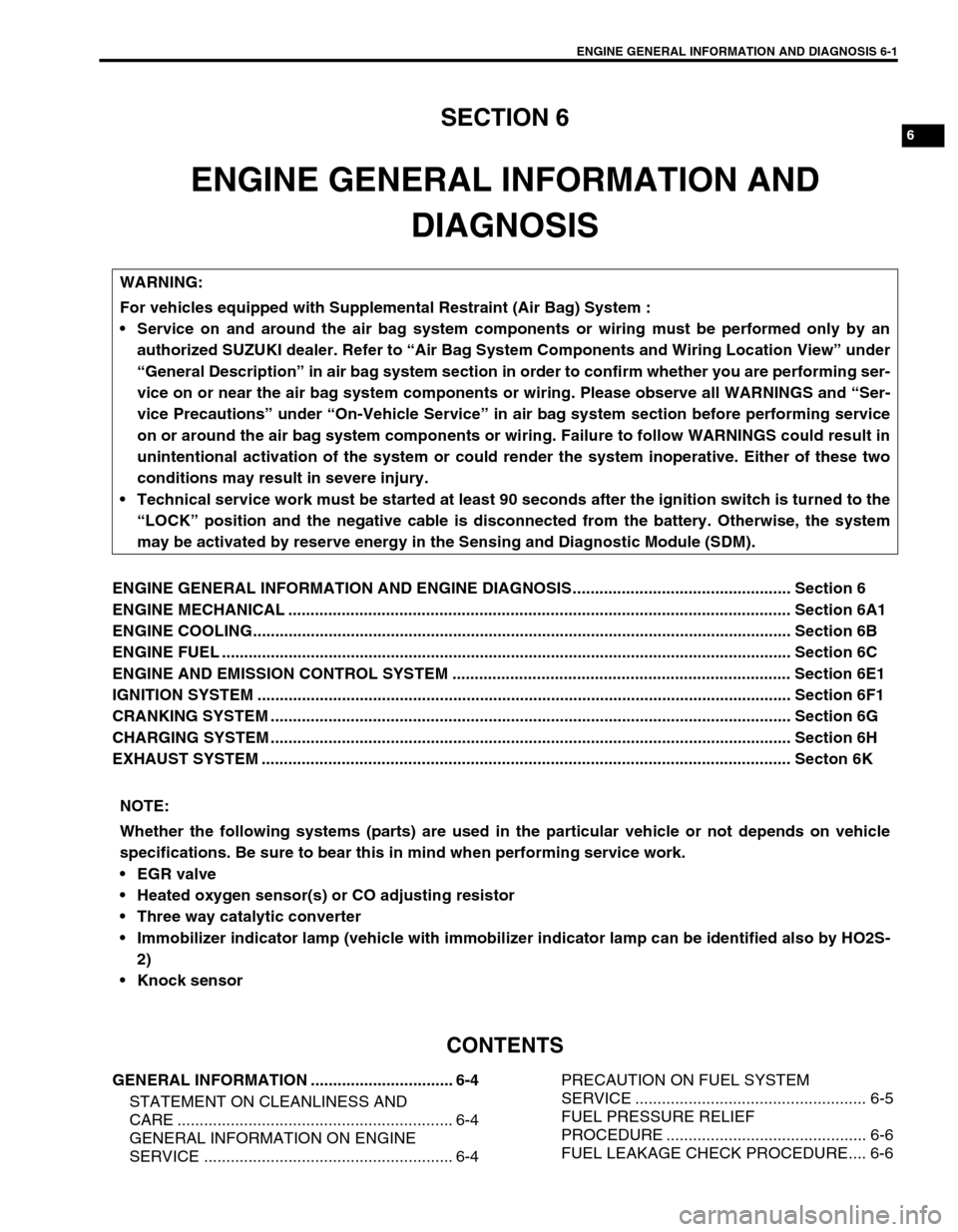
ENGINE GENERAL INFORMATION AND DIAGNOSIS 6-1
6
6F2
6G
6H
6K
7A
7A1
7B1
7C1
7D
7E
7F
8A
8B
8C
8D
8E
9
10A
10B
SECTION 6
ENGINE GENERAL INFORMATION AND
DIAGNOSIS
ENGINE GENERAL INFORMATION AND ENGINE DIAGNOSIS................................................. Section 6
ENGINE MECHANICAL ................................................................................................................. Section 6A1
ENGINE COOLING......................................................................................................................... Section 6B
ENGINE FUEL ................................................................................................................................ Section 6C
ENGINE AND EMISSION CONTROL SYSTEM ............................................................................ Section 6E1
IGNITION SYSTEM ........................................................................................................................ Section 6F1
CRANKING SYSTEM ..................................................................................................................... Section 6G
CHARGING SYSTEM ..................................................................................................................... Section 6H
EXHAUST SYSTEM ....................................................................................................................... Secton 6K
CONTENTS
GENERAL INFORMATION ................................ 6-4
STATEMENT ON CLEANLINESS AND
CARE .............................................................. 6-4
GENERAL INFORMATION ON ENGINE
SERVICE ........................................................ 6-4PRECAUTION ON FUEL SYSTEM
SERVICE .................................................... 6-5
FUEL PRESSURE RELIEF
PROCEDURE ............................................. 6-6
FUEL LEAKAGE CHECK PROCEDURE.... 6-6 WARNING:
For vehicles equipped with Supplemental Restraint (Air Bag) System :
Service on and around the air bag system components or wiring must be performed only by an
authorized SUZUKI dealer. Refer to “Air Bag System Components and Wiring Location View” under
“General Description” in air bag system section in order to confirm whether you are performing ser-
vice on or near the air bag system components or wiring. Please observe all WARNINGS and “Ser-
vice Precautions” under “On-Vehicle Service” in air bag system section before performing service
on or around the air bag system components or wiring. Failure to follow WARNINGS could result in
unintentional activation of the system or could render the system inoperative. Either of these two
conditions may result in severe injury.
Technical service work must be started at least 90 seconds after the ignition switch is turned to the
“LOCK” position and the negative cable is disconnected from the battery. Otherwise, the system
may be activated by reserve energy in the Sensing and Diagnostic Module (SDM).
NOTE:
Whether the following systems (parts) are used in the particular vehicle or not depends on vehicle
specifications. Be sure to bear this in mind when performing service work.
EGR valve
Heated oxygen sensor(s) or CO adjusting resistor
Three way catalytic converter
Immobilizer indicator lamp (vehicle with immobilizer indicator lamp can be identified also by HO2S-
2)
Knock sensor
Page 371 of 698
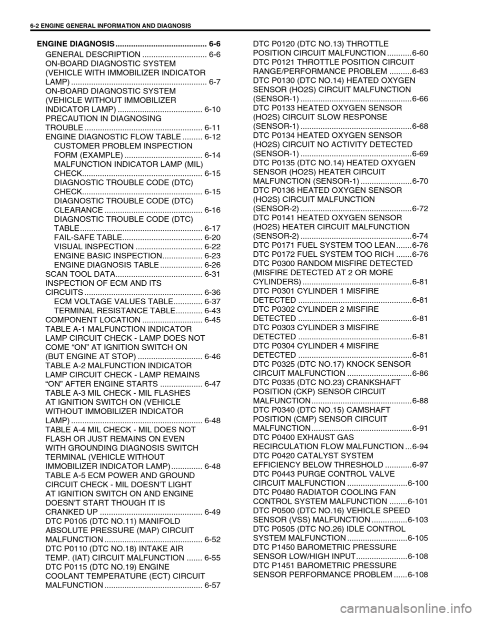
6-2 ENGINE GENERAL INFORMATION AND DIAGNOSIS
ENGINE DIAGNOSIS ......................................... 6-6
GENERAL DESCRIPTION ............................. 6-6
ON-BOARD DIAGNOSTIC SYSTEM
(VEHICLE WITH IMMOBILIZER INDICATOR
LAMP) ............................................................. 6-7
ON-BOARD DIAGNOSTIC SYSTEM
(VEHICLE WITHOUT IMMOBILIZER
INDICATOR LAMP) ...................................... 6-10
PRECAUTION IN DIAGNOSING
TROUBLE ..................................................... 6-11
ENGINE DIAGNOSTIC FLOW TABLE ......... 6-12
CUSTOMER PROBLEM INSPECTION
FORM (EXAMPLE) ................................... 6-14
MALFUNCTION INDICATOR LAMP (MIL)
CHECK...................................................... 6-15
DIAGNOSTIC TROUBLE CODE (DTC)
CHECK...................................................... 6-15
DIAGNOSTIC TROUBLE CODE (DTC)
CLEARANCE ............................................ 6-16
DIAGNOSTIC TROUBLE CODE (DTC)
TABLE ....................................................... 6-17
FAIL-SAFE TABLE.................................... 6-20
VISUAL INSPECTION .............................. 6-22
ENGINE BASIC INSPECTION.................. 6-23
ENGINE DIAGNOSIS TABLE ................... 6-26
SCAN TOOL DATA....................................... 6-31
INSPECTION OF ECM AND ITS
CIRCUITS ..................................................... 6-36
ECM VOLTAGE VALUES TABLE............. 6-37
TERMINAL RESISTANCE TABLE............ 6-43
COMPONENT LOCATION ........................... 6-45
TABLE A-1 MALFUNCTION INDICATOR
LAMP CIRCUIT CHECK - LAMP DOES NOT
COME “ON” AT IGNITION SWITCH ON
(BUT ENGINE AT STOP) ............................. 6-46
TABLE A-2 MALFUNCTION INDICATOR
LAMP CIRCUIT CHECK - LAMP REMAINS
“ON” AFTER ENGINE STARTS ................... 6-47
TABLE A-3 MIL CHECK - MIL FLASHES
AT IGNITION SWITCH ON (VEHICLE
WITHOUT IMMOBILIZER INDICATOR
LAMP) ........................................................... 6-48
TABLE A-4 MIL CHECK - MIL DOES NOT
FLASH OR JUST REMAINS ON EVEN
WITH GROUNDING DIAGNOSIS SWITCH
TERMINAL (VEHICLE WITHOUT
IMMOBILIZER INDICATOR LAMP) .............. 6-48
TABLE A-5 ECM POWER AND GROUND
CIRCUIT CHECK - MIL DOESN’T LIGHT
AT IGNITION SWITCH ON AND ENGINE
DOESN’T START THOUGH IT IS
CRANKED UP .............................................. 6-49
DTC P0105 (DTC NO.11) MANIFOLD
ABSOLUTE PRESSURE (MAP) CIRCUIT
MALFUNCTION ............................................ 6-52
DTC P0110 (DTC NO.18) INTAKE AIR
TEMP. (IAT) CIRCUIT MALFUNCTION ....... 6-55
DTC P0115 (DTC NO.19) ENGINE
COOLANT TEMPERATURE (ECT) CIRCUIT
MALFUNCTION ............................................ 6-57DTC P0120 (DTC NO.13) THROTTLE
POSITION CIRCUIT MALFUNCTION ........... 6-60
DTC P0121 THROTTLE POSITION CIRCUIT
RANGE/PERFORMANCE PROBLEM .......... 6-63
DTC P0130 (DTC NO.14) HEATED OXYGEN
SENSOR (HO2S) CIRCUIT MALFUNCTION
(SENSOR-1) .................................................. 6-66
DTC P0133 HEATED OXYGEN SENSOR
(HO2S) CIRCUIT SLOW RESPONSE
(SENSOR-1) .................................................. 6-68
DTC P0134 HEATED OXYGEN SENSOR
(HO2S) CIRCUIT NO ACTIVITY DETECTED
(SENSOR-1) .................................................. 6-69
DTC P0135 (DTC NO.14) HEATED OXYGEN
SENSOR (HO2S) HEATER CIRCUIT
MALFUNCTION (SENSOR-1) ....................... 6-70
DTC P0136 HEATED OXYGEN SENSOR
(HO2S) CIRCUIT MALFUNCTION
(SENSOR-2) .................................................. 6-72
DTC P0141 HEATED OXYGEN SENSOR
(HO2S) HEATER CIRCUIT MALFUNCTION
(SENSOR-2) .................................................. 6-74
DTC P0171 FUEL SYSTEM TOO LEAN ....... 6-76
DTC P0172 FUEL SYSTEM TOO RICH ....... 6-76
DTC P0300 RANDOM MISFIRE DETECTED
(MISFIRE DETECTED AT 2 OR MORE
CYLINDERS) ................................................. 6-81
DTC P0301 CYLINDER 1 MISFIRE
DETECTED ................................................... 6-81
DTC P0302 CYLINDER 2 MISFIRE
DETECTED ................................................... 6-81
DTC P0303 CYLINDER 3 MISFIRE
DETECTED ................................................... 6-81
DTC P0304 CYLINDER 4 MISFIRE
DETECTED ................................................... 6-81
DTC P0325 (DTC NO.17) KNOCK SENSOR
CIRCUIT MALFUNCTION ............................. 6-86
DTC P0335 (DTC NO.23) CRANKSHAFT
POSITION (CKP) SENSOR CIRCUIT
MALFUNCTION ............................................. 6-88
DTC P0340 (DTC NO.15) CAMSHAFT
POSITION (CMP) SENSOR CIRCUIT
MALFUNCTION ............................................. 6-91
DTC P0400 EXHAUST GAS
RECIRCULATION FLOW MALFUNCTION ... 6-94
DTC P0420 CATALYST SYSTEM
EFFICIENCY BELOW THRESHOLD ............ 6-97
DTC P0443 PURGE CONTROL VALVE
CIRCUIT MALFUNCTION ........................... 6-100
DTC P0480 RADIATOR COOLING FAN
CONTROL SYSTEM MALFUNCTION ........ 6-101
DTC P0500 (DTC NO.16) VEHICLE SPEED
SENSOR (VSS) MALFUNCTION ................ 6-103
DTC P0505 (DTC NO.26) IDLE CONTROL
SYSTEM MALFUNCTION ........................... 6-105
DTC P1450 BAROMETRIC PRESSURE
SENSOR LOW/HIGH INPUT....................... 6-108
DTC P1451 BAROMETRIC PRESSURE
SENSOR PERFORMANCE PROBLEM ...... 6-108
Page 373 of 698
6-4 ENGINE GENERAL INFORMATION AND DIAGNOSIS
GENERAL INFORMATION
STATEMENT ON CLEANLINESS AND CARE
An automobile engine is a combination of many machined, honed, polished and lapped surfaces with tolerances
that are measured in the thousands of an millimeter (ten thousands of an inch).
Accordingly, when any internal engine parts are serviced, care and cleanliness are important.
Throughout this section, it should be understood that proper cleaning and protection of machined surfaces and
friction areas is part of the repair procedure. This is considered standard shop practice even if not specifically
stated.
A liberal coating of engine oil should be applied to friction areas during assembly to protect and lubricate the
surfaces on initial operation.
Whenever valve train components, pistons, piston rings, connecting rods, rod bearings, and crankshaft jour-
nal bearings are removed for service, they should be retained in order.
At the time of installation, they should be installed in the same locations and with the same mating surfaces
as when removed.
Battery cables should be disconnected before any major work is performed on the engine.
Failure to disconnect cables may result in damage to wire harness or other electrical parts.
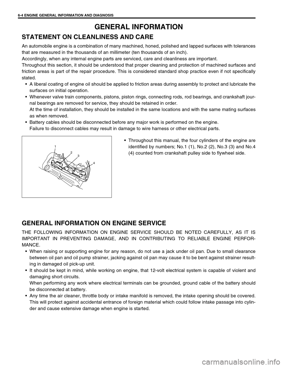
Throughout this manual, the four cylinders of the engine are
identified by numbers; No.1 (1), No.2 (2), No.3 (3) and No.4
(4) counted from crankshaft pulley side to flywheel side.
GENERAL INFORMATION ON ENGINE SERVICE
THE FOLLOWING INFORMATION ON ENGINE SERVICE SHOULD BE NOTED CAREFULLY, AS IT IS
IMPORTANT IN PREVENTING DAMAGE, AND IN CONTRIBUTING TO RELIABLE ENGINE PERFOR-
MANCE.
When raising or supporting engine for any reason, do not use a jack under oil pan. Due to small clearance
between oil pan and oil pump strainer, jacking against oil pan may cause it to be bent against strainer result-
ing in damaged oil pick-up unit.
It should be kept in mind, while working on engine, that 12-volt electrical system is capable of violent and
damaging short circuits.
When performing any work where electrical terminals can be grounded, ground cable of the battery should
be disconnected at battery.
Any time the air cleaner, throttle body or intake manifold is removed, the intake opening should be covered.
This will protect against accidental entrance of foreign material which could follow intake passage into cylin-
der and cause extensive damage when engine is started.
1
2
3
4
Page 387 of 698
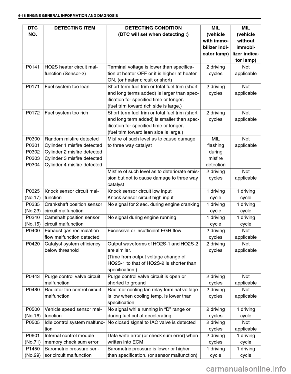
6-18 ENGINE GENERAL INFORMATION AND DIAGNOSIS
P0141 HO2S heater circuit mal-
function (Sensor-2)Terminal voltage is lower than specifica-
tion at heater OFF or it is higher at heater
ON. (or heater circuit or short)2 driving
cyclesNot
applicable
P0171 Fuel system too lean Short term fuel trim or total fuel trim (short
and long terms added) is larger than spec-
ification for specified time or longer.
(fuel trim toward rich side is large.)2 driving
cyclesNot
applicable
P0172 Fuel system too rich Short term fuel trim or total fuel trim (short
and long term added) is smaller than spec-
ification for specified time or longer.
(fuel trim toward lean side is large.)2 driving
cyclesNot
applicable
P0300
P0301
P0302
P0303
P0304Random misfire detected
Cylinder 1 misfire detected
Cylinder 2 misfire detected
Cylinder 3 misfire detected
Cylinder 4 misfire detectedMisfire of such level as to cause damage
to three way catalystMIL
flashing
during
misfire
detectionNot
applicable
Misfire of such level as to deteriorate emis-
sion but not to cause damage to three way
catalyst2 driving
cyclesNot
applicable
P0325
(No.17)Knock sensor circuit mal-
functionKnock sensor circuit low input
Knock sensor circuit high input1 driving
cycle1 driving
cycle
P0335
(No.23)Crankshaft position sensor
circuit malfunctionNo signal for 2 sec. during engine cranking 1 driving
cycle1 driving
cycle
P0340
(No.15)Camshaft position sensor
circuit malfunctionNo signal during engine running 1 driving
cycle1 driving
cycle
P0400 Exhaust gas recirculation
flow malfunction detectedExcessive or insufficient EGR flow 2 driving
cyclesNot
applicable
P0420 Catalyst system efficiency
below thresholdOutput waveforms of HO2S-1 and HO2S-2
are similar.
(Time from output voltage change of
HO2S-1 to that of HO2S-2 is shorter than
specification.)2 driving
cyclesNot
applicable
P0443 Purge control valve circuit
malfunctionPurge control valve circuit is open or
shorted to ground2 driving
cyclesNot
applicable
P0480 Radiator fan control circuit
malfunctionRadiator cooling fan relay terminal voltage
is low when cooling temp. is lower than
specification2 driving
cyclesNot
applicable
P0500
(No.16)Vehicle speed sensor mal-
functionNo signal while running in “D” range or
during fuel cut at decelerating2 driving
cycles1 driving
cycle
P0505 Idle control system malfunc-
tionNo closed signal to IAC valve is detected 2 driving
cyclesNot
applicable
P0601
(No.71)Internal control module
memory check sum errorData write error (or check sum error) when
written into ECM2 driving
cycles1 driving
cycle
P1450
(No.29)Barometric pressure sen-
sor circuit malfunctionBarometric pressure is lower or higher
than specification. (or sensor malfunction)1 driving
cycle1 driving
cycle DTC
NO.DETECTING ITEM DETECTING CONDITION
(DTC will set when detecting :)MIL
(vehicle
with immo-
bilizer indi-
cator lamp)MIL
(vehicle
without
immobi-
lizer indica-
tor lamp)
Page 390 of 698

ENGINE GENERAL INFORMATION AND DIAGNOSIS 6-21
P0340
(No.15)CMP SENSOR ECM changes injection control sys-
tem from sequential injection to simul-
taneous one.Hard starting
P0400 EGR VALVE–Hard starting/rough or incorrect
idle/ excessive fuel consumption/
hesitation/ poor acceleration/
surge/ detonation or spark knock/
engine stall
P0420 CATALYST––
P0443 PURGE CONTROL
VALVE–Rough or incorrect idle/ surge/
hard starting/ engine stall
P0480 RADIATOR FAN
CONTROL SYSTEM–Engine overheating
P0500
(No.16)VEHICLE SPEED
SENSORECM stops idle air control. Rough or incorrect idle
P0505 IDLE CONTROL
SYSTEM–Engine stall/ rough or incorrect idle
P0601
(No.71)ECM INTERNAL–Hard starting/ rough or incorrect
idle/ excessive fuel consumption/
detonation or spark knock/ hesita-
tion poor acceleration/
P1450
(No.29)BAROMETRIC
PRESSURE SEN-
SORECM controls actuators assuming
that barometric pressure is
100 kPa (760 mmHg).Hard starting/ rough or incorrect
idle DTC NO. TROUBLE AREA FAIL-SAFE OPERATION SYMPTOM
Page 395 of 698
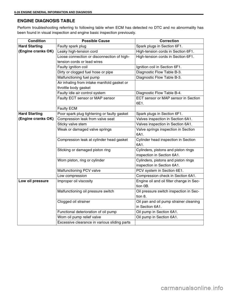
6-26 ENGINE GENERAL INFORMATION AND DIAGNOSIS
ENGINE DIAGNOSIS TABLE
Perform troubleshooting referring to following table when ECM has detected no DTC and no abnormality has
been found in visual inspection and engine basic inspection previously.
Condition Possible Cause Correction
Hard Starting
(Engine cranks OK) Faulty spark plug Spark plugs in Section 6F1.
Leaky high-tension cord High-tension cords in Section 6F1.
Loose connection or disconnection of high-
tension cords or lead wiresHigh-tension cords in Section 6F1.
Faulty ignition coil Ignition coil in Section 6F1.
Dirty or clogged fuel hose or pipe Diagnostic Flow Table B-3.
Malfunctioning fuel pump Diagnostic Flow Table B-3.
Air inhaling from intake manifold gasket or
throttle body gasket
Faulty idle air control system Diagnostic Flow Table B-4.
Faulty ECT sensor or MAP sensor ECT sensor or MAP sensor in Section
6E1.
Faulty ECM
Hard Starting
(Engine cranks OK) Poor spark plug tightening or faulty gasket Spark plugs in Section 6F1.
Compression leak from valve seat Valves inspection in Section 6A1.
Sticky valve stem Valves inspection in Section 6A1.
Weak or damaged valve springs Valve springs inspection in Section
6A1.
Compression leak at cylinder head gasket Cylinder head inspection in Section
6A1.
Sticking or damaged piston ring Cylinders, pistons and piston rings
inspection in Section 6A1.
Worn piston, ring or cylinder Cylinders, pistons and piston rings
inspection in Section 6A1.
Malfunctioning PCV valve PCV system in Section 6E1.
Low compression Compression check in Section 6A1.
Low oil pressure
Improper oil viscosity Engine oil and oil filter change in Sec-
tion 0B.
Malfunctioning oil pressure switch Oil pressure switch inspection in Sec-
tion 8.
Clogged oil strainer Oil pan and oil pump strainer cleaning
in Section 6A1.
Functional deterioration of oil pump Oil pump in Section 6A1.
Worn oil pump relief valve Oil pump in Section 6A1.
Excessive clearance in various sliding parts