4WD SUZUKI SWIFT 2000 1.G RG413 Service Owner's Guide
[x] Cancel search | Manufacturer: SUZUKI, Model Year: 2000, Model line: SWIFT, Model: SUZUKI SWIFT 2000 1.GPages: 698, PDF Size: 16.01 MB
Page 274 of 698
BRAKES 5-1
6F1
6F2
6G
6H
6K
7A
7A1
7B1
7C1
7D
7E
7F
8A
8B
8C
5
9
10
10A
10B
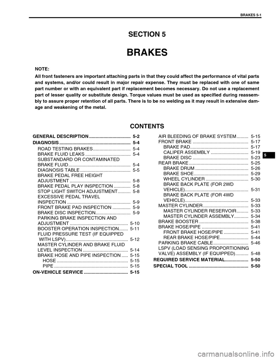
SECTION 5
BRAKES
CONTENTS
GENERAL DESCRIPTION ................................ 5-2
DIAGNOSIS ....................................................... 5-4
ROAD TESTING BRAKES ............................. 5-4
BRAKE FLUID LEAKS ................................... 5-4
SUBSTANDARD OR CONTAMINATED
BRAKE FLUID ................................................ 5-4
DIAGNOSIS TABLE ....................................... 5-5
BRAKE PEDAL FREE HEIGHT
ADJUSTMENT ............................................... 5-8
BRAKE PEDAL PLAY INSPECTION ............. 5-8
STOP LIGHT SWITCH ADJUSTMENT.......... 5-8
EXCESSIVE PEDAL TRAVEL
INSPECTION ................................................. 5-9
FRONT BRAKE PAD INSPECTION .............. 5-9
BRAKE DISC INSPECTION........................... 5-9
PARKING BRAKE INSPECTION AND
ADJUSTMENT ............................................. 5-10
BOOSTER OPERATION INSPECTION....... 5-11
FLUID PRESSURE TEST (IF EQUIPPED
WITH LSPV) ................................................ 5-12
MASTER CYLINDER AND BRAKE FLUID
LEVEL INSPECTION ................................... 5-14
BRAKE HOSE AND PIPE INSPECTION ..... 5-15
HOSE ....................................................... 5-15
PIPE ......................................................... 5-15
ON-VEHICLE SERVICE .................................. 5-15AIR BLEEDING OF BRAKE SYSTEM ......... 5-15
FRONT BRAKE ........................................... 5-17
BRAKE PAD............................................. 5-17
CALIPER ASSEMBLY ............................. 5-19
BRAKE DISC ........................................... 5-23
REAR BRAKE .............................................. 5-25
BRAKE DRUM ......................................... 5-26
BRAKE SHOE .......................................... 5-29
WHEEL CYLINDER ................................. 5-30
BRAKE BACK PLATE (FOR 2WD
VEHICLE)................................................. 5-31
BRAKE BACK PLATE (FOR 4WD
VEHICLE)................................................. 5-33
MASTER CYLINDER ................................... 5-33
MASTER CYLINDER RESERVOIR ......... 5-33
MASTER CYLINDER ASSEMBLY........... 5-34
BRAKE BOOSTER ...................................... 5-38
BRAKE HOSE/PIPE .................................... 5-41
FRONT BRAKE HOSE/PIPE ................... 5-41
REAR BRAKE HOSE/PIPE...................... 5-44
PARKING BRAKE CABLE ........................... 5-46
LSPV (LOAD SENSING PROPORTIONING
VALVE) ASSEMBLY (IF EQUIPPED).......... 5-48
REQUIRED SERVICE MATERIAL.................. 5-50
SPECIAL TOOL .............................................. 5-50
NOTE:
All front fasteners are important attaching parts in that they could affect the performance of vital parts
and systems, and/or could result in major repair expense. They must be replaced with one of same
part number or with an equivalent part if replacement becomes necessary. Do not use a replacement
part of lesser quality or substitute design. Torque values must be used as specified during reassem-
bly to assure proper retention of all parts. There is to be no welding as it may result in extensive dam-
age and weakening of the metal.
Page 300 of 698
BRAKES 5-27
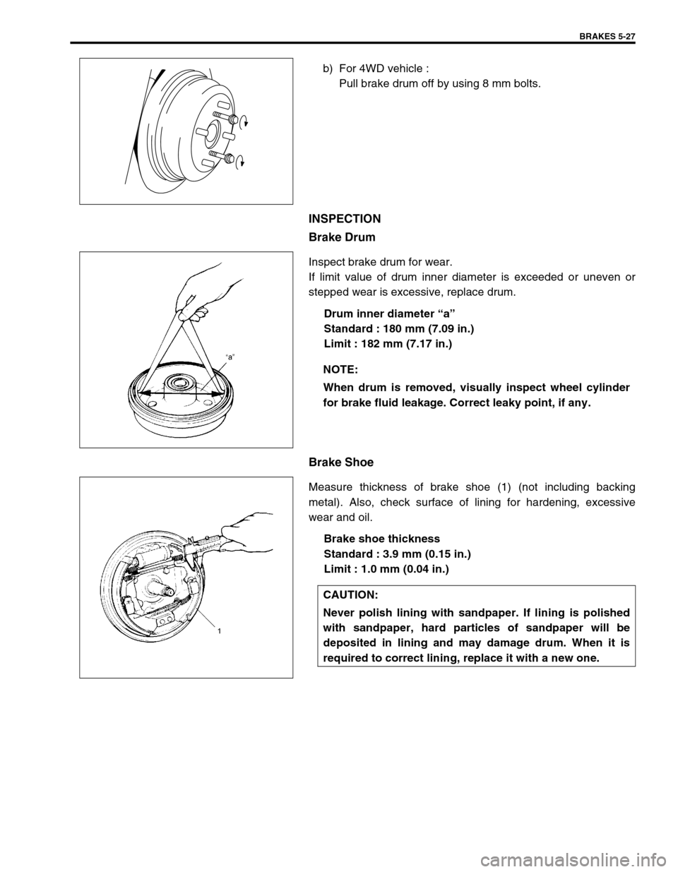
b) For 4WD vehicle :
Pull brake drum off by using 8 mm bolts.
INSPECTION
Brake Drum
Inspect brake drum for wear.
If limit value of drum inner diameter is exceeded or uneven or
stepped wear is excessive, replace drum.
Drum inner diameter “a”
Standard : 180 mm (7.09 in.)
Limit : 182 mm (7.17 in.)
Brake Shoe
Measure thickness of brake shoe (1) (not including backing
metal). Also, check surface of lining for hardening, excessive
wear and oil.
Brake shoe thickness
Standard : 3.9 mm (0.15 in.)
Limit : 1.0 mm (0.04 in.)
NOTE:
When drum is removed, visually inspect wheel cylinder
for brake fluid leakage. Correct leaky point, if any.
CAUTION:
Never polish lining with sandpaper. If lining is polished
with sandpaper, hard particles of sandpaper will be
deposited in lining and may damage drum. When it is
required to correct lining, replace it with a new one.
Page 306 of 698
BRAKES 5-33
BRAKE BACK PLATE (FOR 4WD VEHICLE)
REMOVAL AND INSTALLATION
Refer to “REAR AXLE SHAFT AND WHEEL BEARING (4WD VEHICLE)” in Section 3E.
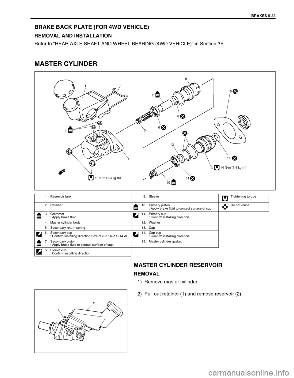
MASTER CYLINDER
MASTER CYLINDER RESERVOIR
REMOVAL
1) Remove master cylinder.
2) Pull out retainer (1) and remove reservoir (2).
1. Reservoir tank 9. Sleeve Tightening torque
2. Retainer 10. Primary piston
: Apply brake fluid to contact surface of cup.Do not reuse.
3. Grommet
: Apply brake fluid.11. Primary cup
: Confirm installing direction.
4. Master cylinder body 12. Washer
5. Secondary return spring 13. Cap
6. Secondary cup
: Confirm installing direction Size of cup : 6=11>14>8 .14. Cap cup
: Confirm installing direction.
7. Secondary piston
: Apply brake fluid to contact surface of cup.15. Master cylinder gasket
8. Sleeve cup
: Confirm installing direction.
2
1
Page 322 of 698
BRAKES 5-49
INSTALLATION
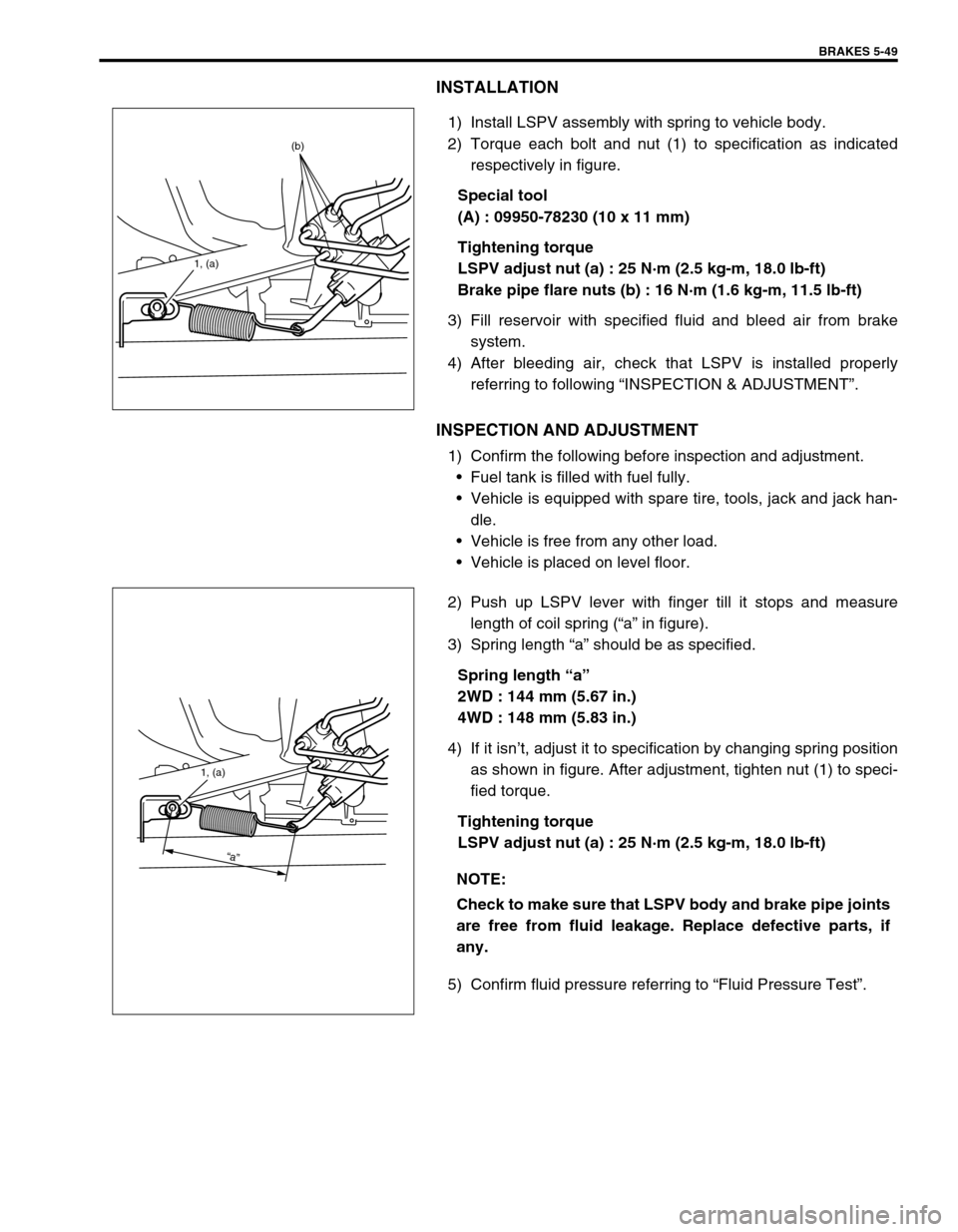
1) Install LSPV assembly with spring to vehicle body.
2) Torque each bolt and nut (1) to specification as indicated
respectively in figure.
Special tool
(A) : 09950-78230 (10 x 11 mm)
Tightening torque
LSPV adjust nut (a) : 25 N·m (2.5 kg-m, 18.0 lb-ft)
Brake pipe flare nuts (b) : 16 N·m (1.6 kg-m, 11.5 lb-ft)
3) Fill reservoir with specified fluid and bleed air from brake
system.
4) After bleeding air, check that LSPV is installed properly
referring to following “INSPECTION & ADJUSTMENT”.
INSPECTION AND ADJUSTMENT
1) Confirm the following before inspection and adjustment.
Fuel tank is filled with fuel fully.
Vehicle is equipped with spare tire, tools, jack and jack han-
dle.
Vehicle is free from any other load.
Vehicle is placed on level floor.
2) Push up LSPV lever with finger till it stops and measure
length of coil spring (“a” in figure).
3) Spring length “a” should be as specified.
Spring length “a”
2WD : 144 mm (5.67 in.)
4WD : 148 mm (5.83 in.)
4) If it isn’t, adjust it to specification by changing spring position
as shown in figure. After adjustment, tighten nut (1) to speci-
fied torque.
Tightening torque
LSPV adjust nut (a) : 25 N·m (2.5 kg-m, 18.0 lb-ft)
5) Confirm fluid pressure referring to “Fluid Pressure Test”.
1, (a)
(b)
NOTE:
Check to make sure that LSPV body and brake pipe joints
are free from fluid leakage. Replace defective parts, if
any.
1, (a)
“a”
Page 323 of 698

5-50 BRAKES
REQUIRED SERVICE MATERIAL
SPECIAL TOOL
MaterialRecommended SUZUKI product
(Part Number)Use
Brake fluid DOT 3 or SAE J1703To fill master cylinder reservoir.
To clean and apply to inner parts of master
cylinder caliper and wheel cylinder when they
are disassembled.
Water tight sealant SEALING COMPOUND 366E
(99000-31090)To apply to mating surfaces of brake back
plate and rear axle (2WD vehicle) or rear
axle housing (4WD vehicle).
To apply to mating surfaces of brake back
plate and parking brake cable.
Lithium grease SUZUKI SUPER GREASE A
(99000-25010)To apply to slide pin of brake caliper carrier.
09900-06106 09900-20606 09900-20701 09942-15510
Snap ring remover Dial gauge Dial gauge chuck Sliding hammer
09943-17912 09951-18220 09952-16020 09952-46010
Brake drum remover
(Front wheel hub
remover)Secondary cup installer
setBooster piston rod
adjusterMaster cylinder attach-
ment
Page 327 of 698

5E-2 ANTILOCK BRAKE SYSTEM (ABS)
DTC C1015 (DTC 15) – G SENSOR
CIRCUIT .................................................... 5E-22
DTC C1021 (DTC 21), DTC C1022
(DTC 22) – RIGHT-FRONT WHEEL
SPEED SENSOR CIRCUIT OR SENSOR
RING .......................................................... 5E-24
DTC C1025 (DTC 25), DTC C1026
(DTC 26) – LEFT-FRONT WHEEL
SPEED SENSOR CIRCUIT OR SENSOR
RING .......................................................... 5E-24
DTC C1031 (DTC 31), DTC C1032
(DTC 32) – RIGHT-REAR WHEEL
SPEED SENSOR CIRCUIT OR SENSOR
RING .......................................................... 5E-24
DTC C1035 (DTC 35), DTC C1036
(DTC 36) – LEFT-REAR WHEEL SPEED
SENSOR CIRCUIT OR SENSOR RING.... 5E-24
DTC C1041 (DTC 41) – RIGHT-FRONT
INLET SOLENOID CIRCUIT...................... 5E-26
DTC C1045 (DTC 45) – LEFT-FRONT
INLET SOLENOID CIRCUIT...................... 5E-26
DTC C1051 (DTC 51) – RIGHT-REAR
INLET SOLENOID CIRCUIT...................... 5E-26
DTC C1055 (DTC 55) – LEFT-REAR
INLET SOLENOID CIRCUIT...................... 5E-26
DTC C1042 (DTC 42) – RIGHT-FRONT
OUTLET SOLENOID CIRCUIT.................. 5E-26
DTC C1046 (DTC 46) – LEFT-FRONT
OUTLET SOLENOID CIRCUIT.................. 5E-26
DTC C1052 (DTC 52) – RIGHT-REAR
OUTLET SOLENOID CIRCUIT.................. 5E-26DTC C1056 (DTC 56) – LEFT-REAR
OUTLET SOLENOID CIRCUIT ................. 5E-26
DTC C1057 (DTC 57) – POWER
SOURCE CIRCUIT .................................... 5E-27
DTC C1061 (DTC 61) – ABS PUMP
MOTOR CIRCUIT ...................................... 5E-28
DTC C1063 (DTC 63) – ABS FAIL-SAFE
RELAY CIRCUIT ....................................... 5E-29
DTC C1071 (DTC 71) – ABS CONTROL
MODULE ................................................... 5E-30
ON-VEHICLE SERVICE................................ 5E-31
PRECAUTIONS ......................................... 5E-31
ABS HYDRAULIC UNIT OPERATION
CHECK (USING SUZUKI SCAN TOOL) ... 5E-31
ABS HYDRAULIC UNIT OPERATION
CHECK (NOT USING SUZUKI SCAN
TOOL) ........................................................ 5E-31
ABS HYDRAULIC UNIT/CONTROL
MODULE ASSEMBLY ............................... 5E-33
FRONT WHEEL SPEED SENSOR ........... 5E-35
FRONT WHEEL SPEED SENSOR
RING .......................................................... 5E-37
REAR WHEEL SPEED SENSOR.............. 5E-38
REAR WHEEL SPEED SENSOR
RING (FOR 2WD VEHICLE) ..................... 5E-41
REAR WHEEL SPEED SENSOR
RING(FOR 4WD VEHICLE) ...................... 5E-42
G SENSOR (FOR 4WD VEHICLE
ONLY) ........................................................ 5E-43
SPECIAL TOOL ............................................ 5E-44
GENERAL DESCRIPTION
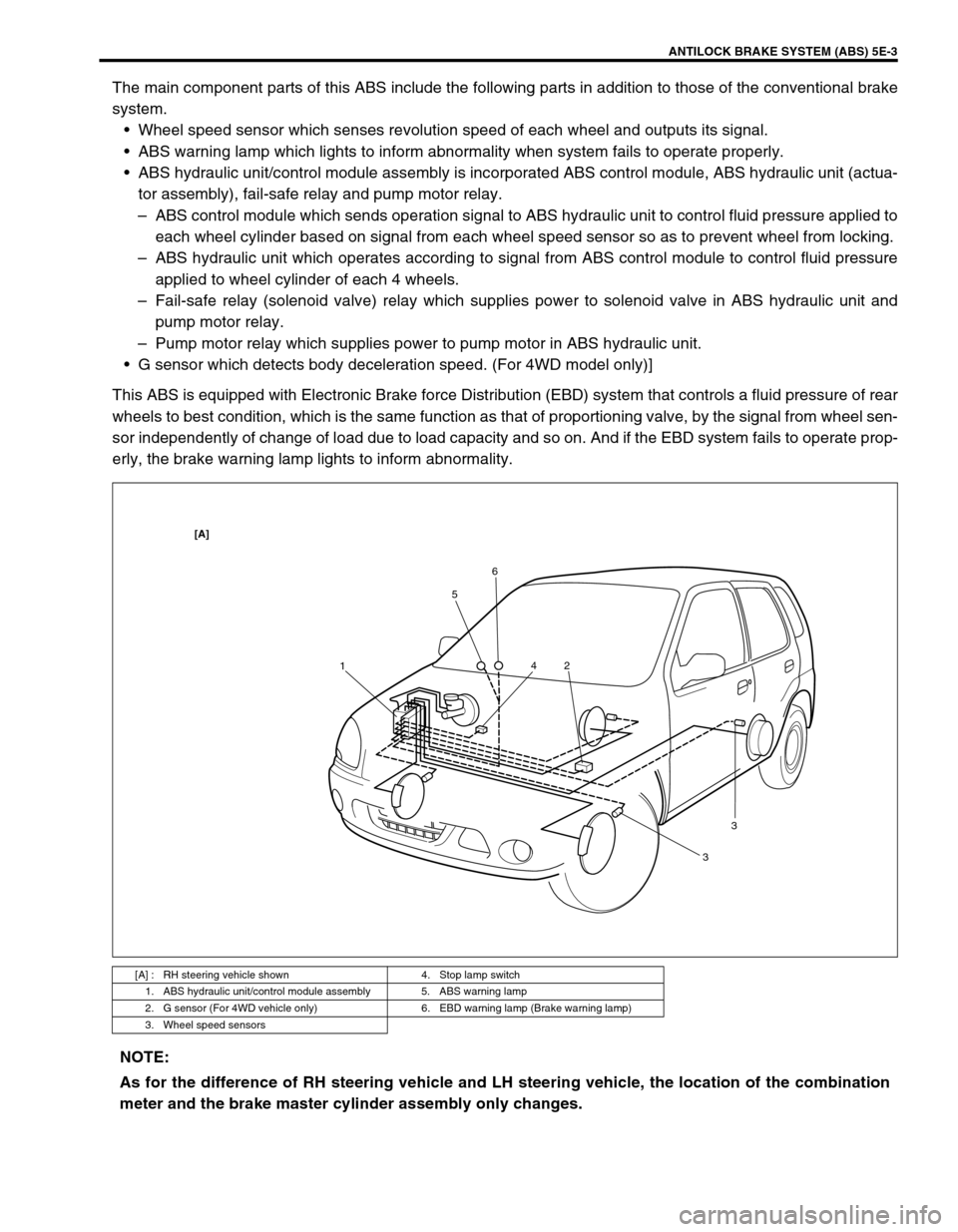
COMPONENTS/PARTS LOCATION AND BRAKE HOSE/PIPE ROUTING
The ABS (Antilock Brake System) controls the fluid pressure applied to the Wheel cylinder of each brake from
the master cylinder so that each wheel is not locked even when hard braking is applied.
This ABS has also the following function.
While braking is applied, but before ABS control becomes effective, braking force is distributed between the front
and rear so as to prevent the rear wheels from being locked too early for better stability of the vehicle.
Page 328 of 698
ANTILOCK BRAKE SYSTEM (ABS) 5E-3
The main component parts of this ABS include the following parts in addition to those of the conventional brake
system.
Wheel speed sensor which senses revolution speed of each wheel and outputs its signal.
ABS warning lamp which lights to inform abnormality when system fails to operate properly.
ABS hydraulic unit/control module assembly is incorporated ABS control module, ABS hydraulic unit (actua-
tor assembly), fail-safe relay and pump motor relay.
–ABS control module which sends operation signal to ABS hydraulic unit to control fluid pressure applied to
each wheel cylinder based on signal from each wheel speed sensor so as to prevent wheel from locking.
–ABS hydraulic unit which operates according to signal from ABS control module to control fluid pressure
applied to wheel cylinder of each 4 wheels.
–Fail-safe relay (solenoid valve) relay which supplies power to solenoid valve in ABS hydraulic unit and
pump motor relay.
–Pump motor relay which supplies power to pump motor in ABS hydraulic unit.
G sensor which detects body deceleration speed. (For 4WD model only)]
This ABS is equipped with Electronic Brake force Distribution (EBD) system that controls a fluid pressure of rear
wheels to best condition, which is the same function as that of proportioning valve, by the signal from wheel sen-
sor independently of change of load due to load capacity and so on. And if the EBD system fails to operate prop-
erly, the brake warning lamp lights to inform abnormality.
[A] : RH steering vehicle shown 4. Stop lamp switch
1. ABS hydraulic unit/control module assembly 5. ABS warning lamp
2. G sensor (For 4WD vehicle only) 6. EBD warning lamp (Brake warning lamp)
3. Wheel speed sensors
156
2 4
33
[A]
NOTE:
As for the difference of RH steering vehicle and LH steering vehicle, the location of the combination
meter and the brake master cylinder assembly only changes.
Page 329 of 698

5E-4 ANTILOCK BRAKE SYSTEM (ABS)
SYSTEM SCHEMATIC
1. ABS hydraulic unit/control module assembly 7.“ABS” warning lamp 13. Wheel speed sensor (Right-front)
2. ABS control module 8.“EBD” warning lamp (Brake warning lamp) 14. Wheel speed sensor (Left-front)
3. ABS hydraulic unit 9. Lamp driver module 15. Wheel speed sensor (Right-rear)
4. Fail safe relay 10. ECM 16. Wheel speed sensor (Left-rear)
5. Pump motor relay 11. Data link connector 17. G sensor (For 4WD vehicle only)
6. Stop lamp switch 12. Monitor coupler
INPUT OUTPUT
ABS control
module Wheel speed sensor (LF)
Wheel speed sensor (LR)
Wheel speed sensor (RF)
Wheel speed sensor (RR)
Stop lamp switch
Diag. switch terminal
Battery Voltage
G sensor (for 4WD vehicle only)
Pump motor
relay
Fail-safe
relay
Hydraulic unit
Pump motor
LF inlet solenoid
LF outlet solenoid
LR inlet solenoid
LR outlet solenoid
RF inlet solenoid
RF outlet solenoid
RR inlet solenoid
RR outlet solenoid
“ABS” warning lamp
ECM
EBD warning lamp
(Brake warning lamp)
Data link connector
ABS hydraulic unit/control
module assembly
Page 332 of 698
ANTILOCK BRAKE SYSTEM (ABS) 5E-7
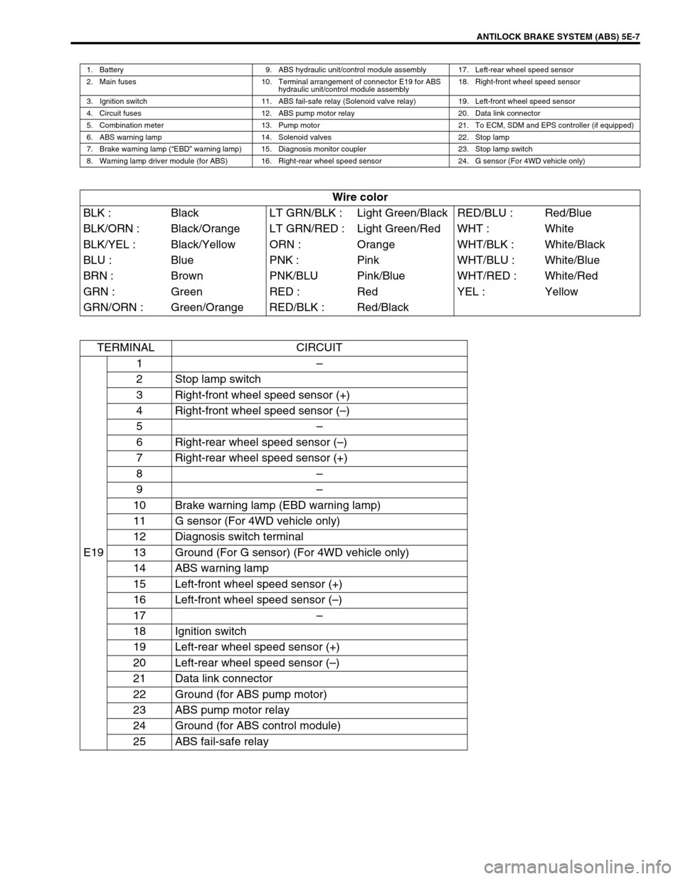
1. Battery 9. ABS hydraulic unit/control module assembly 17. Left-rear wheel speed sensor
2. Main fuses 10. Terminal arrangement of connector E19 for ABS
hydraulic unit/control module assembly18. Right-front wheel speed sensor
3. Ignition switch 11. ABS fail-safe relay (Solenoid valve relay) 19. Left-front wheel speed sensor
4. Circuit fuses 12. ABS pump motor relay 20. Data link connector
5. Combination meter 13. Pump motor 21. To ECM, SDM and EPS controller (if equipped)
6. ABS warning lamp 14. Solenoid valves 22. Stop lamp
7. Brake warning lamp (“EBD” warning lamp) 15. Diagnosis monitor coupler 23. Stop lamp switch
8. Warning lamp driver module (for ABS) 16. Right-rear wheel speed sensor 24. G sensor (For 4WD vehicle only)
Wire color
BLK : Black LT GRN/BLK : Light Green/Black RED/BLU : Red/Blue
BLK/ORN : Black/Orange LT GRN/RED : Light Green/Red WHT : White
BLK/YEL : Black/Yellow ORN : Orange WHT/BLK : White/Black
BLU : Blue PNK : Pink WHT/BLU : White/Blue
BRN : Brown PNK/BLU Pink/Blue WHT/RED : White/Red
GRN : Green RED : Red YEL : Yellow
GRN/ORN : Green/Orange RED/BLK : Red/Black
TERMINAL CIRCUIT
E191–
2 Stop lamp switch
3 Right-front wheel speed sensor (+)
4 Right-front wheel speed sensor (–)
5–
6 Right-rear wheel speed sensor (–)
7 Right-rear wheel speed sensor (+)
8–
9–
10 Brake warning lamp (EBD warning lamp)
11 G sensor (For 4WD vehicle only)
12 Diagnosis switch terminal
13 Ground (For G sensor) (For 4WD vehicle only)
14 ABS warning lamp
15 Left-front wheel speed sensor (+)
16 Left-front wheel speed sensor (–)
17–
18 Ignition switch
19 Left-rear wheel speed sensor (+)
20 Left-rear wheel speed sensor (–)
21 Data link connector
22 Ground (for ABS pump motor)
23 ABS pump motor relay
24 Ground (for ABS control module)
25 ABS fail-safe relay
Page 347 of 698
5E-22 ANTILOCK BRAKE SYSTEM (ABS)
DTC C1013 (DTC 13) – SYSTEM SPECIFICATIONS DIFFERENT FROM ABS
CONTROL MODULE SPECIFICATIONS
DESCRIPTION
When abnormal signal is inputted to a no-used terminal of control module white running or wrong ABS hydraulic
unit/control module assembly is installed, this DTC will be set.
INSPECTION
1) Ignition switch OFF.
2) Check for proper connection from harness to control module.
3) If OK, substitute a known-good and correct specifications ABS hydraulic unit/control module assembly.
4) Recheck system.
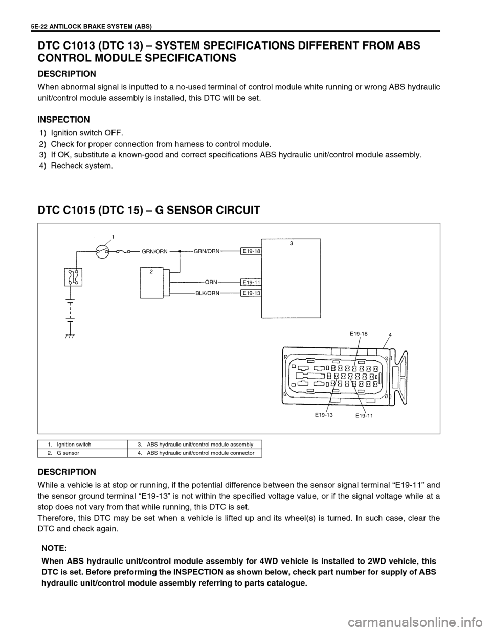
DTC C1015 (DTC 15) – G SENSOR CIRCUIT
DESCRIPTION
While a vehicle is at stop or running, if the potential difference between the sensor signal terminal “E19-11” and
the sensor ground terminal “E19-13” is not within the specified voltage value, or if the signal voltage while at a
stop does not vary from that while running, this DTC is set.
Therefore, this DTC may be set when a vehicle is lifted up and its wheel(s) is turned. In such case, clear the
DTC and check again.
1. Ignition switch 3. ABS hydraulic unit/control module assembly
2. G sensor 4. ABS hydraulic unit/control module connector
NOTE:
When ABS hydraulic unit/control module assembly for 4WD vehicle is installed to 2WD vehicle, this
DTC is set. Before preforming the INSPECTION as shown below, check part number for supply of ABS
hydraulic unit/control module assembly referring to parts catalogue.