4WD SUZUKI SWIFT 2000 1.G RG413 Service User Guide
[x] Cancel search | Manufacturer: SUZUKI, Model Year: 2000, Model line: SWIFT, Model: SUZUKI SWIFT 2000 1.GPages: 698, PDF Size: 16.01 MB
Page 50 of 698
MAINTENANCE AND LUBRICATION 0B-21
STEERING
Check to ensure that steering wheel is free from instability, or abnormally heavy feeling.
Check that the vehicle does not wander or pull to one side.
ENGINE
Check that engine responds readily at all speeds.
Check that engine is free from abnormal noise and abnormal vibration.
BODY, WHEELS AND POWER TRANSMITTING SYSTEM
Check that body, wheels and power transmitting system are free from abnormal noise and abnormal vibration or
any other abnormal condition.
METERS AND GAUGE
Check that speedometer, odometer, fuel meter, temperature gauge, etc. are operating accurately.
LIGHTS
Check that all lights operate properly.
WINDSHIELD DEFROSTER
Periodically check that air comes out from defroster outlet when operating heater or air conditioning.
Set mode control lever to defroster position and fan switch lever to “HI” position for this check.
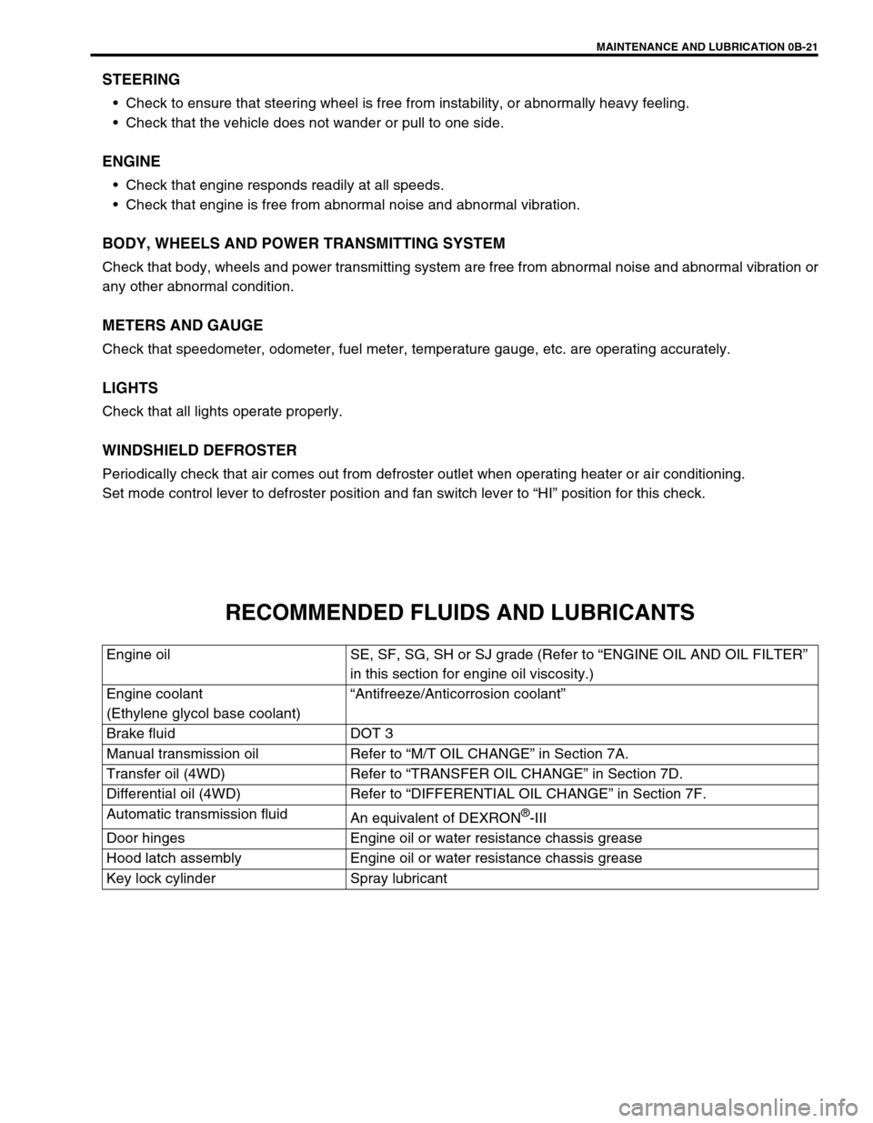
RECOMMENDED FLUIDS AND LUBRICANTS
Engine oil SE, SF, SG, SH or SJ grade (Refer to “ENGINE OIL AND OIL FILTER”
in this section for engine oil viscosity.)
Engine coolant
(Ethylene glycol base coolant)“Antifreeze/Anticorrosion coolant”
Brake fluid DOT 3
Manual transmission oil Refer to “M/T OIL CHANGE” in Section 7A.
Transfer oil (4WD) Refer to “TRANSFER OIL CHANGE” in Section 7D.
Differential oil (4WD) Refer to “DIFFERENTIAL OIL CHANGE” in Section 7F.
Automatic transmission fluid
An equivalent of DEXRON
®-III
Door hinges Engine oil or water resistance chassis grease
Hood latch assembly Engine oil or water resistance chassis grease
Key lock cylinder Spray lubricant
Page 119 of 698
3A-2 FRONT END ALIGNMENT
GENERAL DESCRIPTION
Front alignment refers to the angular relationship between the
front wheels, the front suspension attaching parts and the ground.
Generally, the only adjustment required for front alignment is toe
setting.
Camber and caster can’t be adjusted. Therefore, should camber
or caster be out of specification due to the damage caused by
hazardous road conditions or collision, whether the damage is in
body or in suspension should be determined. If the body is dam-
aged, it should be repaired and if suspension is damaged, it
should be replaced.
TOE SETTING
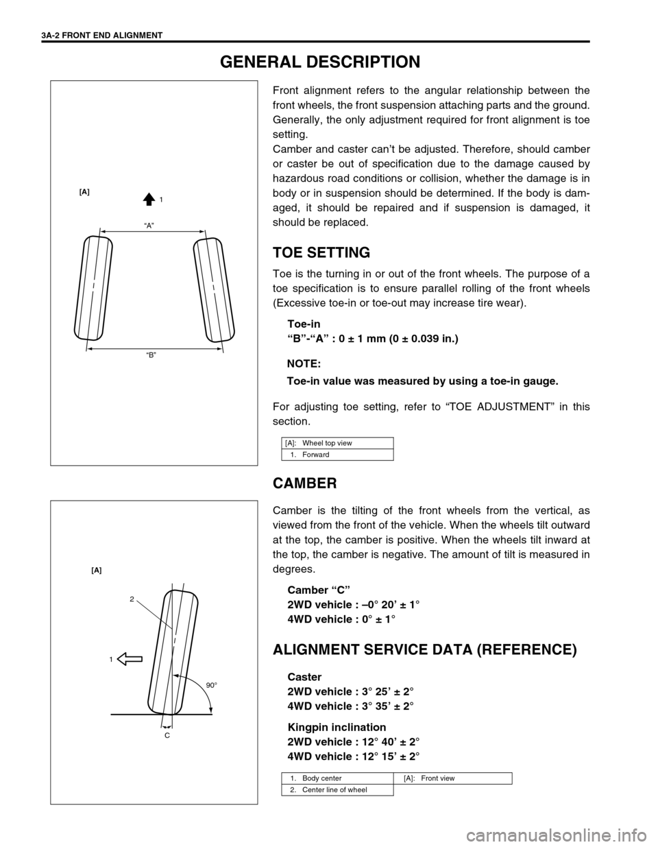
Toe is the turning in or out of the front wheels. The purpose of a
toe specification is to ensure parallel rolling of the front wheels
(Excessive toe-in or toe-out may increase tire wear).
Toe-in
“B”-“A” : 0 ± 1 mm (0 ± 0.039 in.)
For adjusting toe setting, refer to “TOE ADJUSTMENT” in this
section.
CAMBER
Camber is the tilting of the front wheels from the vertical, as
viewed from the front of the vehicle. When the wheels tilt outward
at the top, the camber is positive. When the wheels tilt inward at
the top, the camber is negative. The amount of tilt is measured in
degrees.
Camber “C”
2WD vehicle : –0° 20’ ± 1°
4WD vehicle : 0° ± 1°
ALIGNMENT SERVICE DATA (REFERENCE)
Caster
2WD vehicle : 3° 25’ ± 2°
4WD vehicle : 3° 35’ ± 2°
Kingpin inclination
2WD vehicle : 12° 40’ ± 2°
4WD vehicle : 12° 15’ ± 2° NOTE:
Toe-in value was measured by using a toe-in gauge.
[A]: Wheel top view
1. Forward
“A”
“B”1 [A]
1. Body center [A]: Front view
2. Center line of wheel
2
1
90
o
C [A]
Page 129 of 698
3B-8 MANUAL RACK AND PINION
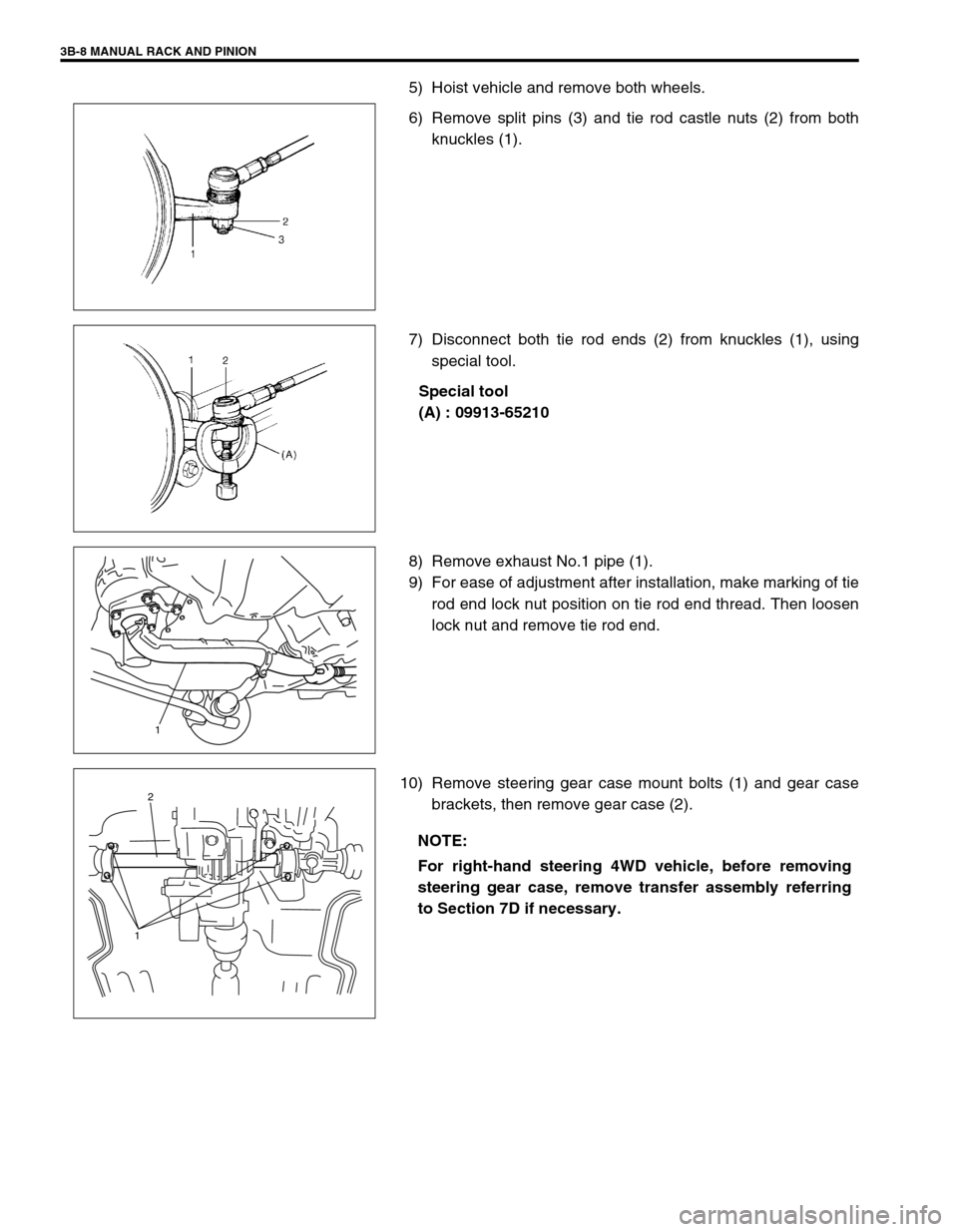
5) Hoist vehicle and remove both wheels.
6) Remove split pins (3) and tie rod castle nuts (2) from both
knuckles (1).
7) Disconnect both tie rod ends (2) from knuckles (1), using
special tool.
Special tool
(A) : 09913-65210
8) Remove exhaust No.1 pipe (1).
9) For ease of adjustment after installation, make marking of tie
rod end lock nut position on tie rod end thread. Then loosen
lock nut and remove tie rod end.
10) Remove steering gear case mount bolts (1) and gear case
brackets, then remove gear case (2).
1
NOTE:
For right-hand steering 4WD vehicle, before removing
steering gear case, remove transfer assembly referring
to Section 7D if necessary.
2
1
Page 214 of 698
REAR SUSPENSION 3E-1
6F1
6F2
6G
1A
6K
7A
7A1
7B1
7C1
3E
8A
8B
8C
8D
8E
9
10
10A
10B
SECTION 3E
REAR SUSPENSION
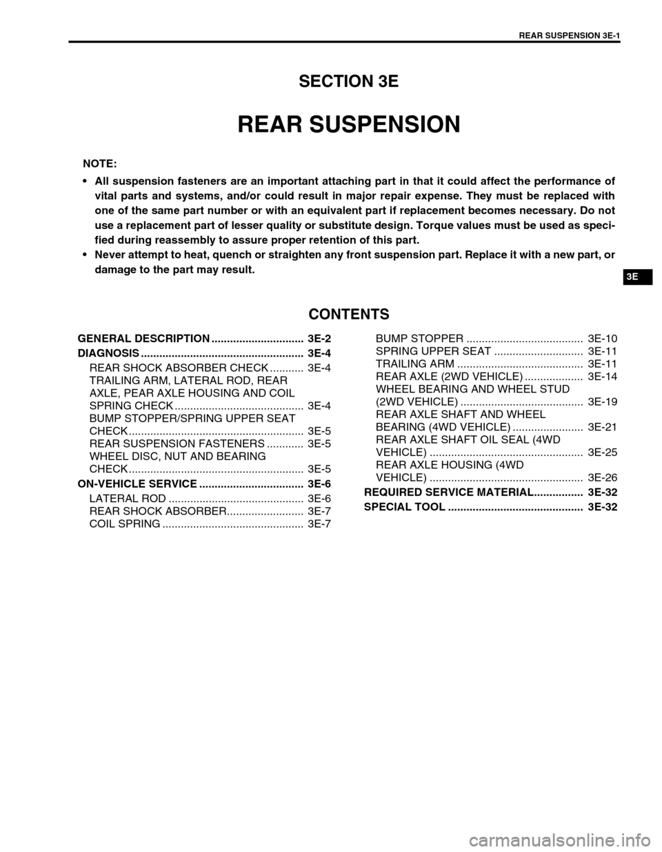
CONTENTS
GENERAL DESCRIPTION .............................. 3E-2
DIAGNOSIS ..................................................... 3E-4
REAR SHOCK ABSORBER CHECK ........... 3E-4
TRAILING ARM, LATERAL ROD, REAR
AXLE, PEAR AXLE HOUSING AND COIL
SPRING CHECK .......................................... 3E-4
BUMP STOPPER/SPRING UPPER SEAT
CHECK ......................................................... 3E-5
REAR SUSPENSION FASTENERS ............ 3E-5
WHEEL DISC, NUT AND BEARING
CHECK ......................................................... 3E-5
ON-VEHICLE SERVICE .................................. 3E-6
LATERAL ROD ............................................ 3E-6
REAR SHOCK ABSORBER......................... 3E-7
COIL SPRING .............................................. 3E-7BUMP STOPPER ...................................... 3E-10
SPRING UPPER SEAT ............................. 3E-11
TRAILING ARM ......................................... 3E-11
REAR AXLE (2WD VEHICLE) ................... 3E-14
WHEEL BEARING AND WHEEL STUD
(2WD VEHICLE) ........................................ 3E-19
REAR AXLE SHAFT AND WHEEL
BEARING (4WD VEHICLE) ....................... 3E-21
REAR AXLE SHAFT OIL SEAL (4WD
VEHICLE) .................................................. 3E-25
REAR AXLE HOUSING (4WD
VEHICLE) .................................................. 3E-26
REQUIRED SERVICE MATERIAL................ 3E-32
SPECIAL TOOL ............................................ 3E-32
NOTE:
All suspension fasteners are an important attaching part in that it could affect the performance of
vital parts and systems, and/or could result in major repair expense. They must be replaced with
one of the same part number or with an equivalent part if replacement becomes necessary. Do not
use a replacement part of lesser quality or substitute design. Torque values must be used as speci-
fied during reassembly to assure proper retention of this part.
Never attempt to heat, quench or straighten any front suspension part. Replace it with a new part, or
damage to the part may result.
Page 216 of 698
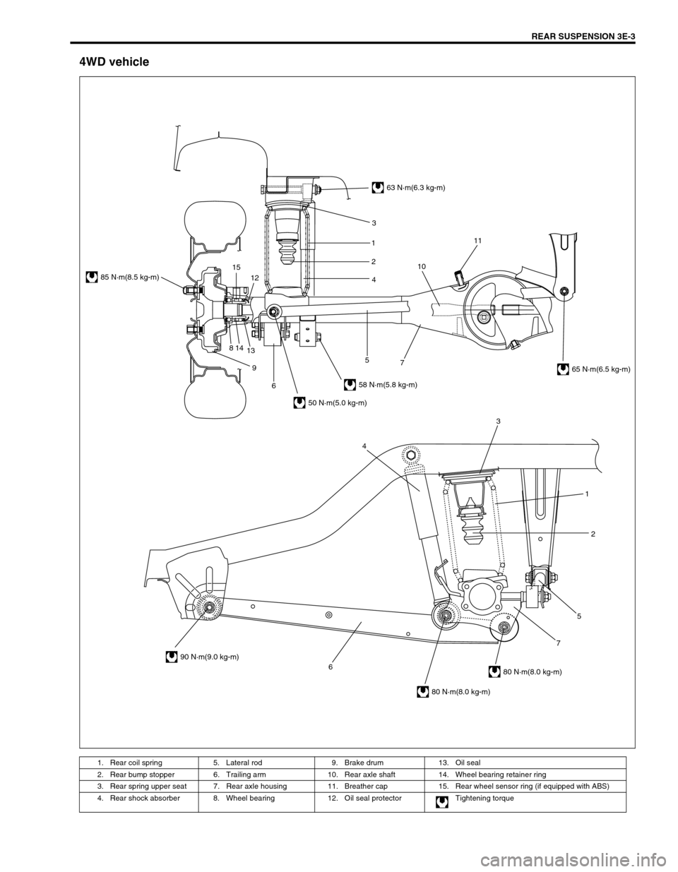
REAR SUSPENSION 3E-3
4WD vehicle
1. Rear coil spring 5. Lateral rod 9. Brake drum 13. Oil seal
2. Rear bump stopper 6. Trailing arm 10. Rear axle shaft 14. Wheel bearing retainer ring
3. Rear spring upper seat 7. Rear axle housing 11. Breather cap 15. Rear wheel sensor ring (if equipped with ABS)
4. Rear shock absorber 8. Wheel bearing 12. Oil seal protector Tightening torque
6752 1 3
4
63 N·m(6.3 kg-m)
58 N·m(5.8 kg-m)
50 N·m(5.0 kg-m)
85 N·m(8.5 kg-m)
90 N·m(9.0 kg-m)
80 N·m(8.0 kg-m)
80 N·m(8.0 kg-m)
65 N·m(6.5 kg-m) 3
1
2
4
7 5
6 9 814
1312 151011
Page 218 of 698

REAR SUSPENSION 3E-5
BUMP STOPPER/SPRING UPPER SEAT
CHECK
Inspect for cracks, deformation or damage.
Replace any defective part.
REAR SUSPENSION FASTENERS
Check each bolt and nut fastening suspension parts for tightness.
Tighten loose one, if any, to specified torque referring to the figure
in “GENERAL DESCRIPTION” in this section.
WHEEL DISC, NUT AND BEARING CHECK
Inspect each wheel disc for dents, distortion and cracks.
A disc in badly damaged condition must be replaced.
Check wheel nuts for tightness and, as necessary, retighten
to specification.
Tightening torque
Wheel nuts (a) : 85 N·m (8.5 kg-m, 61.5 lb-ft)
Check wheel bearings for wear. When measuring thrust
play, apply a dial gauge to spindle cap center (2WD) or axle
shaft center (4WD).
Thrust play limit
“a” : 0.1 mm (0.004 in.)
When measurement exceeds limit, replace bearing.
[A] : 2WD VEHICLE
[B] : 4WD VEHICLE
Page 219 of 698

3E-6 REAR SUSPENSION
By rotating wheel actually, check wheel bearing for noise
and smooth rotation. If it is defective, replace bearing.
ON-VEHICLE SERVICE
LATERAL ROD
REMOVAL
1) Hoist vehicle.
2) Remove lateral rod nuts (1) and bolt (2).
3) Remove lateral rod (3).
INSTALLATION
1) Install lateral rod (1) to rear axle (2) (2WD vehicle) or rear
axle housing (4WD vehicle) and vehicle body (3) referring to
figure for proper installing direction of nuts (4), bolt (5) and
washer (6).
Tighten nuts temporarily at this step.
2) Lower hoist.
[A] : Forward
[B] : Body side
[C] : Rear axle (2WD vehicle) or rear axle housing (4WD vehicle) side
21643
5
[A]
Page 220 of 698

REAR SUSPENSION 3E-7
3) Tighten lateral rod nuts (1) to specified torque. It is the most
desirable to have vehicle off hoist and in no-loaded condition
when tightening them.
Tightening torque
Lateral rod left side nut (a) : 50 N·m (5.0 kg-m, 36.5 lb-ft)
Lateral rod right side nut (b) : 65 N·m (6.5 kg-m, 47.0 lb-ft)
REAR SHOCK ABSORBER
REMOVAL
1) Hoist vehicle.
2) Support rear axle (1) (2WD vehicle) or rear axle housing
(4WD vehicle) using floor jack to prevent it from lowering.
3) Remove lower bolt (2).
4) Remove upper bolt (3) and nut (4). Then remove shock
absorber (5).
INSTALLATION
1) Install shock absorber (5) referring to the figure.
Tighten bolt and nut temporarily at this step.
2) Remove floor jack from rear axle (2WD vehicle) or rear axle
housing (4WD vehicle) (1) and lower hoist.
3) Tighten bolt and nut to specified torque.
Tightening torque
Rear shock absorber upper nut
(a) : 63 N·m (6.3 kg-m, 46.0 lb-ft)
Rear shock absorber lower nut
(b) : 58 N·m (5.8 kg-m, 42.0 lb-ft)
COIL SPRING
REMOVAL
1) Hoist vehicle and remove rear wheel (s).
2) Support rear axle (1) (2WD vehicle) or rear axle housing
(4WD vehicle) using floor jack (2) to prevent it from lowering.
A : Vehicle inside
Page 221 of 698

3E-8 REAR SUSPENSION
3) Remove lateral rod right side bolt (1) and nut (2).
4) Detach lateral rod right side from vehicle body.
5) Remove brake flexible hose E-ring (1).
6) Remove LSPV adjust nut and detach spring end from rear
axle (2WD vehicle) or axle housing (4WD vehicle) (if
equipped with LSPV).
7) Remove shock absorber lower bolt (1).
8) Detach shock absorber lower side from rear axle (2WD vehi-
cle) or rear axle housing (4WD vehicle).
9) Lower rear axle (1) (2WD vehicle) or rear axle housing (4WD
vehicle) gradually as far down as where coil springs (2) can
be removed.
10) Remove coil spring.
CAUTION:
Be careful not to let rear axle (2WD vehicle) or rear axle
housing (4WD vehicle) down too much.
It may cause damage to brake flexible hose.
Page 222 of 698

REAR SUSPENSION 3E-9
INSTALLATION
1) Install coil springs (1) (right & left) on spring seat (2) of rear
axle (2WD vehicle) or rear axle housing (4WD vehicle) and
raise rear axle (2WD vehicle) or rear axle housing (4WD
vehicle).
2) Install shock absorber (1) lower side to rear axle (2WD vehi-
cle) or rear axle housing (4WD vehicle).
Tighten shock absorber lower bolt (2) temporarily at this
step.
3) Remove floor jack from rear axle (2WD vehicle) or axle
housing (4WD vehicle).
4) Install brake flexible hose E-ring.
5) Install LSPV spring to rear axle (2WD vehicle) or axle hous-
ing (4WD vehicle). Tighten LSPV adjust nut temporarily at
this step (if equipped with LSPV).
6) Install lateral rod (1) right side to vehicle body, refer to the
figure for proper installing direction of bolt (2).
Tighten nut (3) temporarily at this step.
7) Remove floor jack from rear axle (2WD vehicle) or rear axle
housing (4WD vehicle).
8) Install wheel (1) and tighten wheel nuts (2) to specified
torque.
Tightening torque
Wheel nuts (a) : 85 N·m (8.5 kg-m, 61.5 lb-ft) NOTE:
Upper and lower diameters of coil spring are different.
Bring larger diameter end at bottom and set its open end
in place on spring seat.
A : Upper side
A : Forward