ECU SUZUKI SWIFT 2000 1.G RG413 Service Repair Manual
[x] Cancel search | Manufacturer: SUZUKI, Model Year: 2000, Model line: SWIFT, Model: SUZUKI SWIFT 2000 1.GPages: 698, PDF Size: 16.01 MB
Page 611 of 698
6C-4 ENGINE FUEL
FUEL LINES
INSPECTION
Visually inspect fuel lines for evidence of fuel leakage, hose crack
and deterioration, or damage.
Make sure all clamps are secure.
Replace parts as needed.
FUEL PIPE
REMOVAL
1) Relieve fuel pressure in fuel feed line according to “FUEL
PRESSURE RELIEF PROCEDURE” in Section 6.
2) Disconnect negative cable at battery.
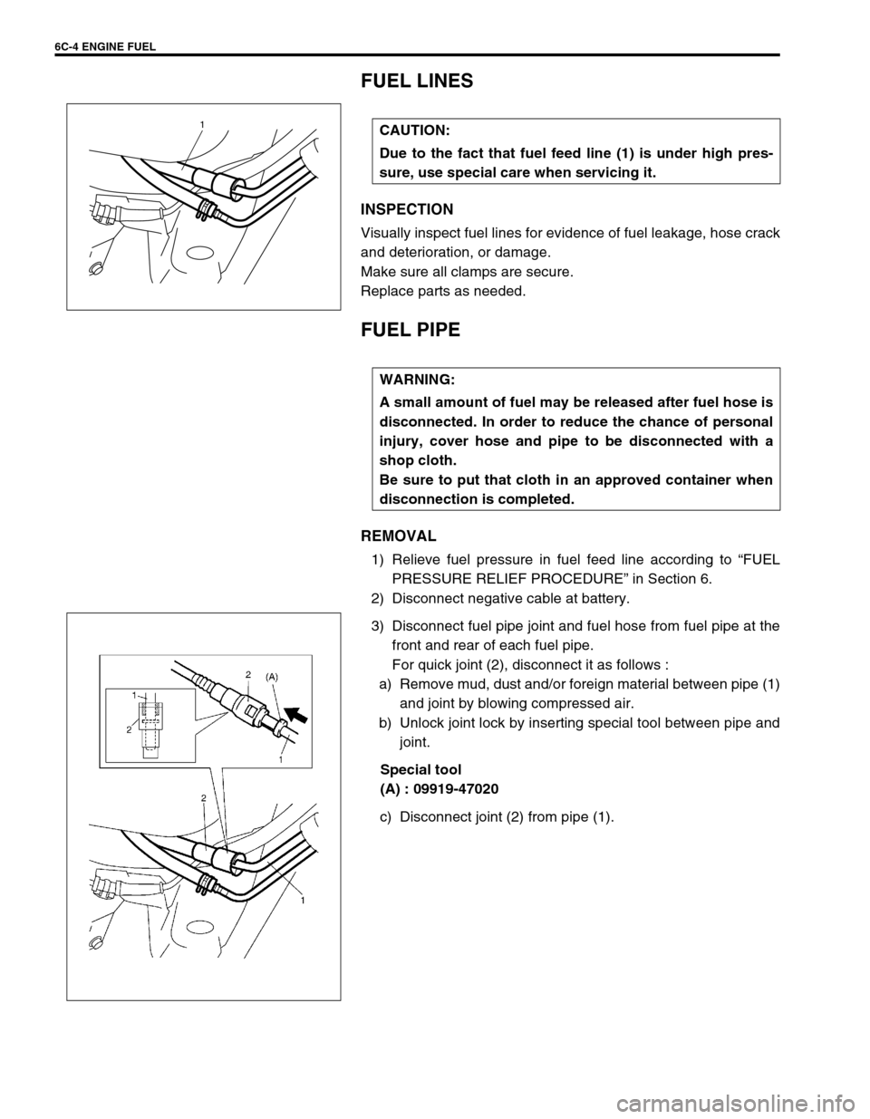
3) Disconnect fuel pipe joint and fuel hose from fuel pipe at the
front and rear of each fuel pipe.
For quick joint (2), disconnect it as follows :
a) Remove mud, dust and/or foreign material between pipe (1)
and joint by blowing compressed air.
b) Unlock joint lock by inserting special tool between pipe and
joint.
Special tool
(A) : 09919-47020
c) Disconnect joint (2) from pipe (1). CAUTION:
Due to the fact that fuel feed line (1) is under high pres-
sure, use special care when servicing it.
1
WARNING:
A small amount of fuel may be released after fuel hose is
disconnected. In order to reduce the chance of personal
injury, cover hose and pipe to be disconnected with a
shop cloth.
Be sure to put that cloth in an approved container when
disconnection is completed.
Page 612 of 698
ENGINE FUEL 6C-5
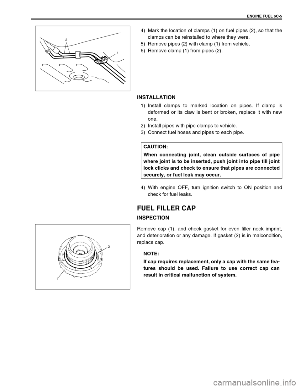
4) Mark the location of clamps (1) on fuel pipes (2), so that the
clamps can be reinstalled to where they were.
5) Remove pipes (2) with clamp (1) from vehicle.
6) Remove clamp (1) from pipes (2).
INSTALLATION
1) Install clamps to marked location on pipes. If clamp is
deformed or its claw is bent or broken, replace it with new
one.
2) Install pipes with pipe clamps to vehicle.
3) Connect fuel hoses and pipes to each pipe.
4) With engine OFF, turn ignition switch to ON position and
check for fuel leaks.
FUEL FILLER CAP
INSPECTION
Remove cap (1), and check gasket for even filler neck imprint,
and deterioration or any damage. If gasket (2) is in malcondition,
replace cap.
2
1
CAUTION:
When connecting joint, clean outside surfaces of pipe
where joint is to be inserted, push joint into pipe till joint
lock clicks and check to ensure that pipes are connected
securely, or fuel leak may occur.
NOTE:
If cap requires replacement, only a cap with the same fea-
tures should be used. Failure to use correct cap can
result in critical malfunction of system.
Page 614 of 698
ENGINE FUEL 6C-7
INSTALLATION
1) Install fuel tank inlet valve (1) to fuel tank.
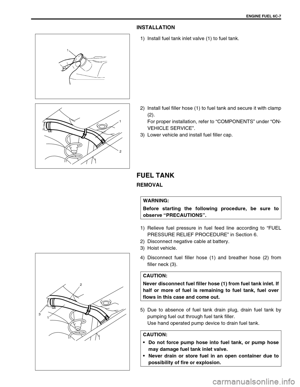
2) Install fuel filler hose (1) to fuel tank and secure it with clamp
(2).
For proper installation, refer to “COMPONENTS” under “ON-
VEHICLE SERVICE”.
3) Lower vehicle and install fuel filler cap.
FUEL TANK
REMOVAL
1) Relieve fuel pressure in fuel feed line according to “FUEL
PRESSURE RELIEF PROCEDURE” in Section 6.
2) Disconnect negative cable at battery.
3) Hoist vehicle.
4) Disconnect fuel filler hose (1) and breather hose (2) from
filler neck (3).
5) Due to absence of fuel tank drain plug, drain fuel tank by
pumping fuel out through fuel tank filler.
Use hand operated pump device to drain fuel tank.
1
2
WARNING:
Before starting the following procedure, be sure to
observe “PRECAUTIONS”.
CAUTION:
Never disconnect fuel filler hose (1) from fuel tank inlet. If
half or more of fuel is remaining to fuel tank, fuel over
flows in this case and come out.
CAUTION:
Do not force pump hose into fuel tank, or pump hose
may damage fuel tank inlet valve.
Never drain or store fuel in an open container due to
possibility of fire or explosion.
2
1
3
Page 616 of 698
ENGINE FUEL 6C-9
FUEL TANK PURGING PROCEDURE
The following procedure is used for purging fuel tank.
1) After removing fuel tank, remove all hoses, pipes, fuel pump
assembly from fuel tank.
2) Drain all remaining fuel from tank.
3) Move tank to flushing area.
4) Fill tank with warm water or tap water, and agitate vigorously
and drain. Repeat this washing until inside of tank is clean.
Replace tank if its inside is rusty.
5) Completely flush out remaining water after washing.
INSTALLATION
1) If parts have been removed from fuel tank, install them
before installing fuel tank to vehicle.
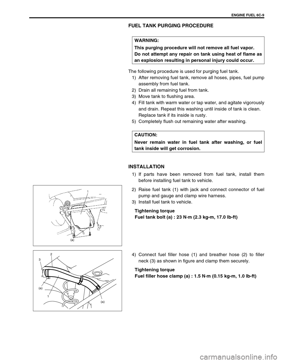
2) Raise fuel tank (1) with jack and connect connector of fuel
pump and gauge and clamp wire harness.
3) Install fuel tank to vehicle.
Tightening torque
Fuel tank bolt (a) : 23 N·m (2.3 kg-m, 17.0 lb-ft)
4) Connect fuel filler hose (1) and breather hose (2) to filler
neck (3) as shown in figure and clamp them securely.
Tightening torque
Fuel filler hose clamp (a) : 1.5 N·m (0.15 kg-m, 1.0 lb-ft) WARNING:
This purging procedure will not remove all fuel vapor.
Do not attempt any repair on tank using heat of flame as
an explosion resulting in personal injury could occur.
CAUTION:
Never remain water in fuel tank after washing, or fuel
tank inside will get corrosion.
(a) (a)
1 32
Page 617 of 698
6C-10 ENGINE FUEL
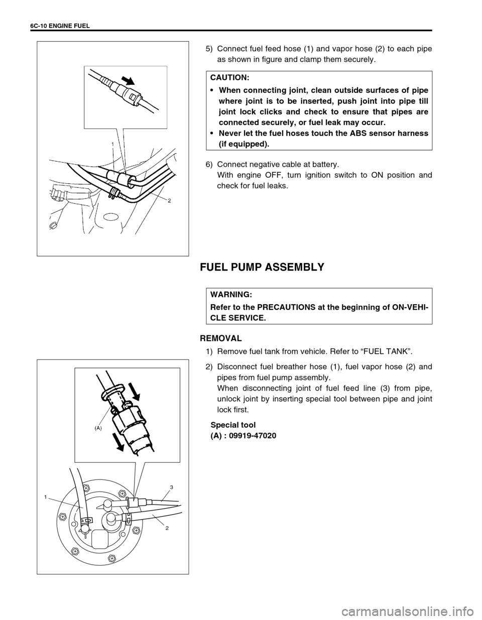
5) Connect fuel feed hose (1) and vapor hose (2) to each pipe
as shown in figure and clamp them securely.
6) Connect negative cable at battery.
With engine OFF, turn ignition switch to ON position and
check for fuel leaks.
FUEL PUMP ASSEMBLY
REMOVAL
1) Remove fuel tank from vehicle. Refer to “FUEL TANK”.
2) Disconnect fuel breather hose (1), fuel vapor hose (2) and
pipes from fuel pump assembly.
When disconnecting joint of fuel feed line (3) from pipe,
unlock joint by inserting special tool between pipe and joint
lock first.
Special tool
(A) : 09919-47020 CAUTION:
When connecting joint, clean outside surfaces of pipe
where joint is to be inserted, push joint into pipe till
joint lock clicks and check to ensure that pipes are
connected securely, or fuel leak may occur.
Never let the fuel hoses touch the ABS sensor harness
(if equipped).
WARNING:
Refer to the PRECAUTIONS at the beginning of ON-VEHI-
CLE SERVICE.
1
23
Page 619 of 698
6C-12 ENGINE FUEL
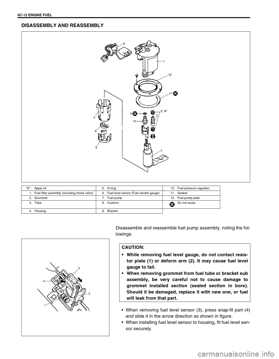
DISASSEMBLY AND REASSEMBLY
Disassemble and reassemble fuel pump assembly, noting the fol-
lowings.
When removing fuel level sensor (3), press snap-fit part (4)
and slide it in the arrow direction as shown in figure.
When installing fuel level sensor to housing, fit fuel level sen-
sor securely.
“A” : Apply oil 5. O-ring 10. Fuel pressure regulator
1. Fuel filter assembly (including check valve) 6. Fuel level sensor (Fuel sender gauge) 11. Gasket
2. Grommet 7. Fuel pump 12. Fuel pump plate
3. Tube 8. Cushion Do not reuse.
4. Housing 9. Bracket
CAUTION:
While removing fuel level gauge, do not contact resis-
tor plate (1) or deform arm (2). It may cause fuel level
gauge to fail.
When removing grommet from fuel tube or bracket sub
assembly, be very careful not to cause damage to
grommet installed section (sealed section in bore).
Should it be damaged, replace it with new one, or fuel
will leak from that part.
Page 620 of 698
ENGINE FUEL 6C-13
INSTALLATION
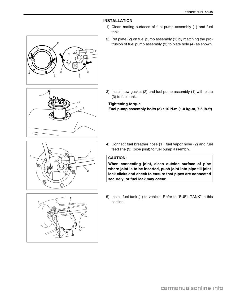
1) Clean mating surfaces of fuel pump assembly (1) and fuel
tank.
2) Put plate (2) on fuel pump assembly (1) by matching the pro-
trusion of fuel pump assembly (3) to plate hole (4) as shown.
3) Install new gasket (2) and fuel pump assembly (1) with plate
(3) to fuel tank.
Tightening torque
Fuel pump assembly bolts (a) : 10 N·m (1.0 kg-m, 7.5 lb-ft)
4) Connect fuel breather hose (1), fuel vapor hose (2) and fuel
feed line (3) (pipe joint) to fuel pump assembly.
5) Install fuel tank (1) to vehicle. Refer to “FUEL TANK” in this
section.
3 2
4 43
1
3
1
2
(a)
CAUTION:
When connecting joint, clean outside surface of pipe
where joint is to be inserted, push joint into pipe till joint
lock clicks and check to ensure that pipes are connected
securely, or fuel leak may occur.1
23
Page 636 of 698
ENGINE AND EMISSION CONTROL SYSTEM 6E1-15
ON-VEHICLE SERVICE
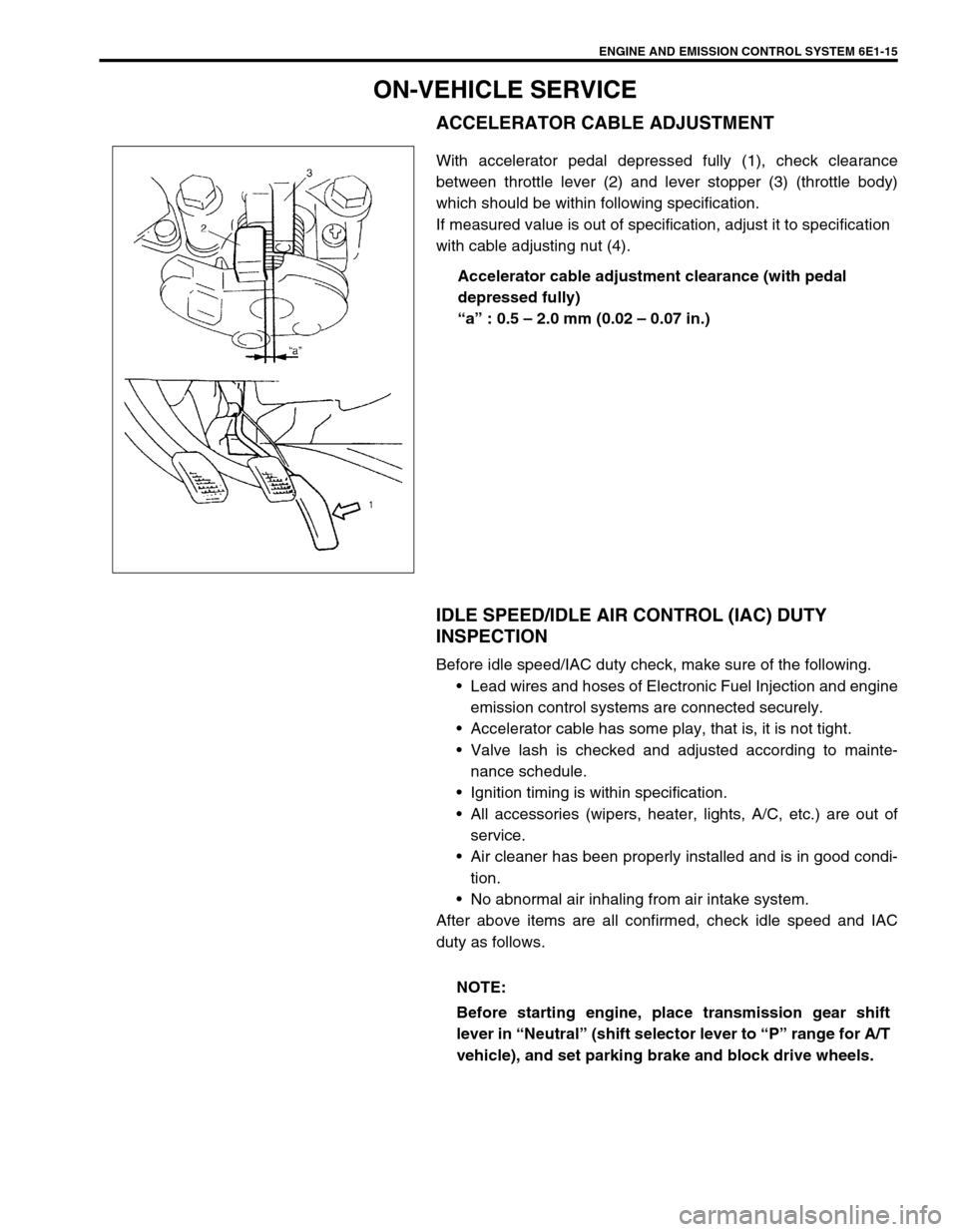
ACCELERATOR CABLE ADJUSTMENT
With accelerator pedal depressed fully (1), check clearance
between throttle lever (2) and lever stopper (3) (throttle body)
which should be within following specification.
If measured value is out of specification, adjust it to specification
with cable adjusting nut (4).
Accelerator cable adjustment clearance (with pedal
depressed fully)
“a” : 0.5 – 2.0 mm (0.02 – 0.07 in.)
IDLE SPEED/IDLE AIR CONTROL (IAC) DUTY
INSPECTION
Before idle speed/IAC duty check, make sure of the following.
Lead wires and hoses of Electronic Fuel Injection and engine
emission control systems are connected securely.
Accelerator cable has some play, that is, it is not tight.
Valve lash is checked and adjusted according to mainte-
nance schedule.
Ignition timing is within specification.
All accessories (wipers, heater, lights, A/C, etc.) are out of
service.
Air cleaner has been properly installed and is in good condi-
tion.
No abnormal air inhaling from air intake system.
After above items are all confirmed, check idle speed and IAC
duty as follows.
NOTE:
Before starting engine, place transmission gear shift
lever in “Neutral” (shift selector lever to “P” range for A/T
vehicle), and set parking brake and block drive wheels.
Page 641 of 698
6E1-20 ENGINE AND EMISSION CONTROL SYSTEM
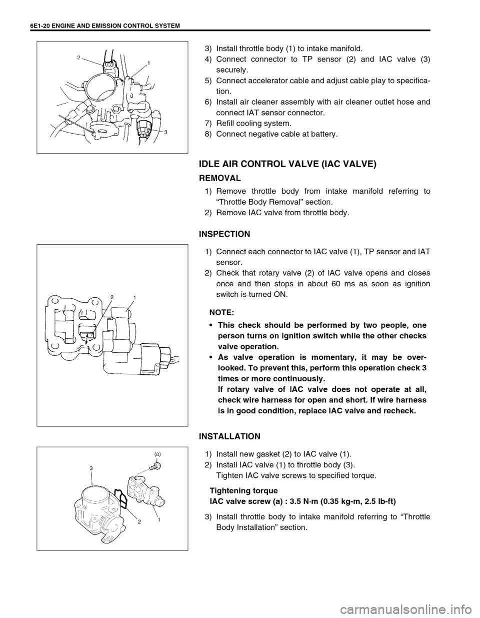
3) Install throttle body (1) to intake manifold.
4) Connect connector to TP sensor (2) and IAC valve (3)
securely.
5) Connect accelerator cable and adjust cable play to specifica-
tion.
6) Install air cleaner assembly with air cleaner outlet hose and
connect IAT sensor connector.
7) Refill cooling system.
8) Connect negative cable at battery.
IDLE AIR CONTROL VALVE (IAC VALVE)
REMOVAL
1) Remove throttle body from intake manifold referring to
“Throttle Body Removal” section.
2) Remove IAC valve from throttle body.
INSPECTION
1) Connect each connector to IAC valve (1), TP sensor and IAT
sensor.
2) Check that rotary valve (2) of lAC valve opens and closes
once and then stops in about 60 ms as soon as ignition
switch is turned ON.
INSTALLATION
1) Install new gasket (2) to IAC valve (1).
2) Install IAC valve (1) to throttle body (3).
Tighten IAC valve screws to specified torque.
Tightening torque
IAC valve screw (a) : 3.5 N·m (0.35 kg-m, 2.5 lb-ft)
3) Install throttle body to intake manifold referring to “Throttle
Body Installation” section.
NOTE:
This check should be performed by two people, one
person turns on ignition switch while the other checks
valve operation.
As valve operation is momentary, it may be over-
looked. To prevent this, perform this operation check 3
times or more continuously.
If rotary valve of lAC valve does not operate at all,
check wire harness for open and short. If wire harness
is in good condition, replace lAC valve and recheck.
Page 642 of 698
ENGINE AND EMISSION CONTROL SYSTEM 6E1-21
FUEL DELIVERY SYSTEM
FUEL PRESSURE INSPECTION
1) Relieve fuel pressure in fuel feed line referring to “Fuel Pres-
sure Relief Procedure” in Section 6.
2) Disconnect fuel feed hose from fuel delivery pipe.
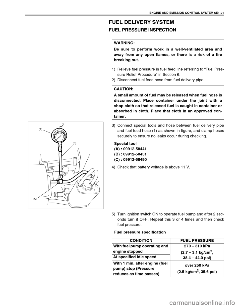
3) Connect special tools and hose between fuel delivery pipe
and fuel feed hose (1) as shown in figure, and clamp hoses
securely to ensure no leaks occur during checking.
Special tool
(A) : 09912-58441
(B) : 09912-58431
(C) : 09912-58490
4) Check that battery voltage is above 11 V.
5) Turn ignition switch ON to operate fuel pump and after 2 sec-
onds turn it OFF. Repeat this 3 or 4 times and then check
fuel pressure.
Fuel pressure specification WARNING:
Be sure to perform work in a well-ventilated area and
away from any open flames, or there is a risk of a fire
breaking out.
CAUTION:
A small amount of fuel may be released when fuel hose is
disconnected. Place container under the joint with a
shop cloth so that released fuel is caught in container or
absorbed in cloth. Place that cloth in an approved con-
tainer.
(A)
(B)
(C)1
CONDITION FUEL PRESSURE
With fuel pump operating and
engine stopped270 – 310 kPa
(2.7 – 3.1 kg/cm
2,
38.4 – 44.0 psi) At specified idle speed
With 1 min. after engine (fuel
pump) stop (Pressure
reduces as time passes)over 250 kPa
(2.5 kg/cm
2, 35.6 psi)