Electric system SUZUKI SWIFT 2000 1.G RG413 Service Repair Manual
[x] Cancel search | Manufacturer: SUZUKI, Model Year: 2000, Model line: SWIFT, Model: SUZUKI SWIFT 2000 1.GPages: 698, PDF Size: 16.01 MB
Page 593 of 698
6B-4 ENGINE COOLING
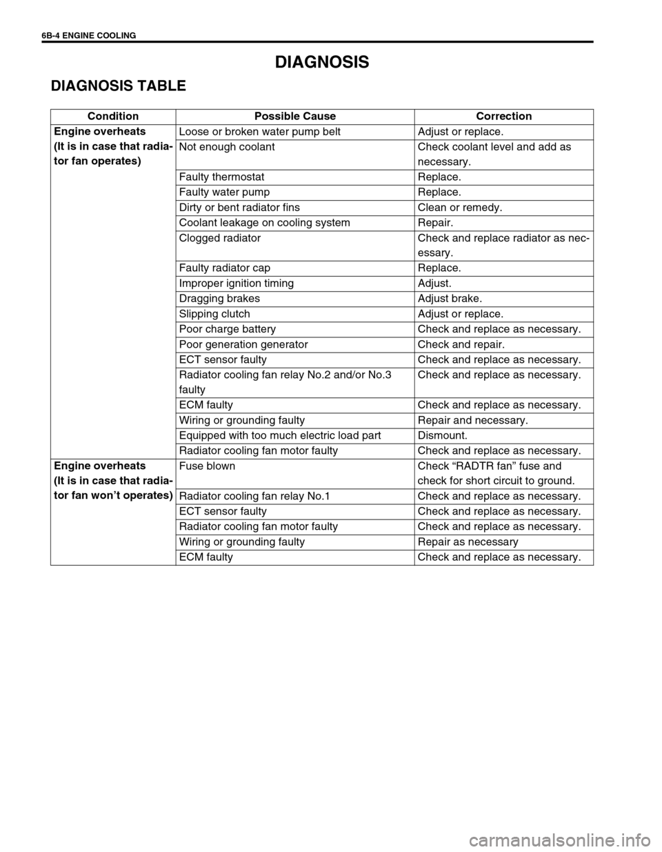
DIAGNOSIS
DIAGNOSIS TABLE
Condition Possible Cause Correction
Engine overheats
(It is in case that radia-
tor fan operates)Loose or broken water pump belt Adjust or replace.
Not enough coolant Check coolant level and add as
necessary.
Faulty thermostat Replace.
Faulty water pump Replace.
Dirty or bent radiator fins Clean or remedy.
Coolant leakage on cooling system Repair.
Clogged radiator Check and replace radiator as nec-
essary.
Faulty radiator cap Replace.
Improper ignition timing Adjust.
Dragging brakes Adjust brake.
Slipping clutch Adjust or replace.
Poor charge battery Check and replace as necessary.
Poor generation generator Check and repair.
ECT sensor faulty Check and replace as necessary.
Radiator cooling fan relay No.2 and/or No.3
faultyCheck and replace as necessary.
ECM faulty Check and replace as necessary.
Wiring or grounding faulty Repair and necessary.
Equipped with too much electric load part Dismount.
Radiator cooling fan motor faulty Check and replace as necessary.
Engine overheats
(It is in case that radia-
tor fan won’t operates)Fuse blown Check “RADTR fan” fuse and
check for short circuit to ground.
Radiator cooling fan relay No.1 Check and replace as necessary.
ECT sensor faulty Check and replace as necessary.
Radiator cooling fan motor faulty Check and replace as necessary.
Wiring or grounding faulty Repair as necessary
ECM faulty Check and replace as necessary.
Page 626 of 698
ENGINE AND EMISSION CONTROL SYSTEM 6E1-5
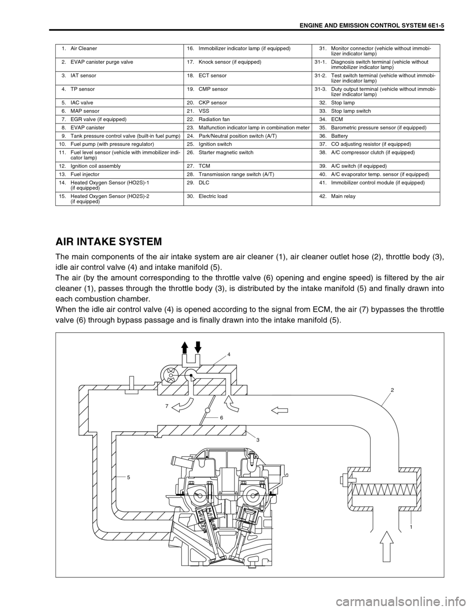
AIR INTAKE SYSTEM
The main components of the air intake system are air cleaner (1), air cleaner outlet hose (2), throttle body (3),
idle air control valve (4) and intake manifold (5).
The air (by the amount corresponding to the throttle valve (6) opening and engine speed) is filtered by the air
cleaner (1), passes through the throttle body (3), is distributed by the intake manifold (5) and finally drawn into
each combustion chamber.
When the idle air control valve (4) is opened according to the signal from ECM, the air (7) bypasses the throttle
valve (6) through bypass passage and is finally drawn into the intake manifold (5).
1. Air Cleaner 16. Immobilizer indicator lamp (if equipped) 31. Monitor connector (vehicle without immobi-
lizer indicator lamp)
2. EVAP canister purge valve 17. Knock sensor (if equipped) 31-1. Diagnosis switch terminal (vehicle without
immobilizer indicator lamp)
3. IAT sensor 18. ECT sensor 31-2. Test switch terminal (vehicle without immobi-
lizer indicator lamp)
4. TP sensor 19. CMP sensor 31-3. Duty output terminal (vehicle without immobi-
lizer indicator lamp)
5. IAC valve 20. CKP sensor 32. Stop lamp
6. MAP sensor 21. VSS 33. Stop lamp switch
7. EGR valve (if equipped) 22. Radiation fan 34. ECM
8. EVAP canister 23. Malfunction indicator lamp in combination meter 35. Barometric pressure sensor (if equipped)
9. Tank pressure control valve (built-in fuel pump) 24. Park/Neutral position switch (A/T) 36. Battery
10. Fuel pump (with pressure regulator) 25. Ignition switch 37. CO adjusting resistor (if equipped)
11. Fuel level sensor (vehicle with immobilizer indi-
cator lamp)26. Starter magnetic switch 38. A/C compressor clutch (if equipped)
12. Ignition coil assembly 27. TCM 39. A/C switch (if equipped)
13. Fuel injector 28. Transmission range switch (A/T) 40. A/C evaporator temp. sensor (if equipped)
14. Heated Oxygen Sensor (HO2S)-1
(if equipped)29. DLC 41. Immobilizer control module (if equipped)
15. Heated Oxygen Sensor (HO2S)-2
(if equipped)30. Electric load 42. Main relay
54
2
1
6
3
7
Page 627 of 698
6E1-6 ENGINE AND EMISSION CONTROL SYSTEM
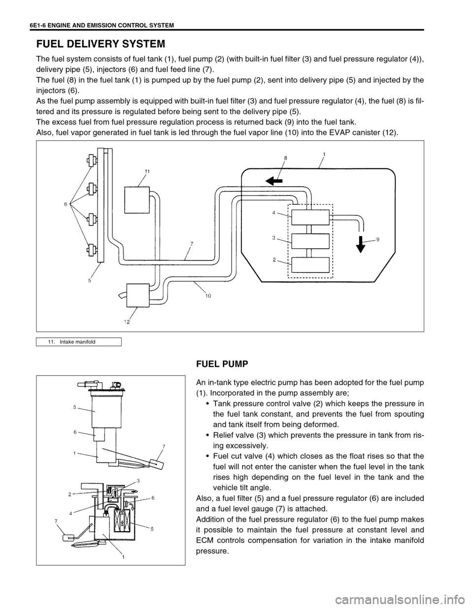
FUEL DELIVERY SYSTEM
The fuel system consists of fuel tank (1), fuel pump (2) (with built-in fuel filter (3) and fuel pressure regulator (4)),
delivery pipe (5), injectors (6) and fuel feed line (7).
The fuel (8) in the fuel tank (1) is pumped up by the fuel pump (2), sent into delivery pipe (5) and injected by the
injectors (6).
As the fuel pump assembly is equipped with built-in fuel filter (3) and fuel pressure regulator (4), the fuel (8) is fil-
tered and its pressure is regulated before being sent to the delivery pipe (5).
The excess fuel from fuel pressure regulation process is returned back (9) into the fuel tank.
Also, fuel vapor generated in fuel tank is led through the fuel vapor line (10) into the EVAP canister (12).
FUEL PUMP
An in-tank type electric pump has been adopted for the fuel pump
(1). Incorporated in the pump assembly are;
Tank pressure control valve (2) which keeps the pressure in
the fuel tank constant, and prevents the fuel from spouting
and tank itself from being deformed.
Relief valve (3) which prevents the pressure in tank from ris-
ing excessively.
Fuel cut valve (4) which closes as the float rises so that the
fuel will not enter the canister when the fuel level in the tank
rises high depending on the fuel level in the tank and the
vehicle tilt angle.
Also, a fuel filter (5) and a fuel pressure regulator (6) are included
and a fuel level gauge (7) is attached.
Addition of the fuel pressure regulator (6) to the fuel pump makes
it possible to maintain the fuel pressure at constant level and
ECM controls compensation for variation in the intake manifold
pressure.
11. Intake manifold
Page 629 of 698
6E1-8 ENGINE AND EMISSION CONTROL SYSTEM
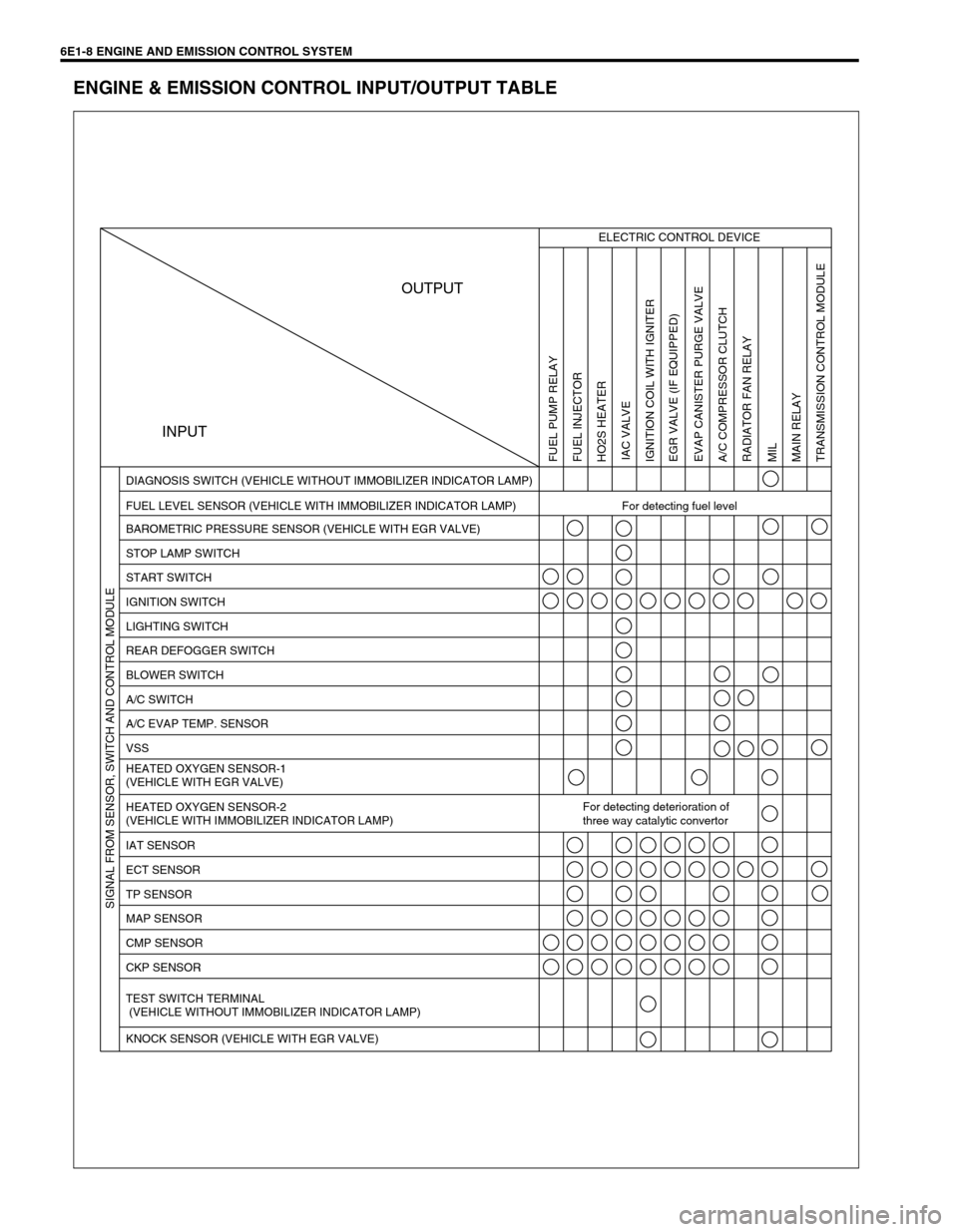
ENGINE & EMISSION CONTROL INPUT/OUTPUT TABLE
INPUTOUTPUT
ELECTRIC CONTROL DEVICE
FUEL LEVEL SENSOR (VEHICLE WITH IMMOBILIZER INDICATOR LAMP) For detecting fuel level DIAGNOSIS SWITCH (VEHICLE WITHOUT IMMOBILIZER INDICATOR LAMP)
BAROMETRIC PRESSURE SENSOR (VEHICLE WITH EGR VALVE)
STOP LAMP SWITCH
START SWITCH
IGNITION SWITCH
LIGHTING SWITCH
REAR DEFOGGER SWITCH
BLOWER SWITCH
A/C SWITCH
A/C EVAP TEMP. SENSOR
VSS
HEATED OXYGEN SENSOR-1
(VEHICLE WITH EGR VALVE)
HEATED OXYGEN SENSOR-2
(VEHICLE WITH IMMOBILIZER INDICATOR LAMP)For detecting deterioration of
three way catalytic convertor
IAT SENSOR
ECT SENSOR
TP SENSOR
MAP SENSOR
CMP SENSOR
CKP SENSOR
TEST SWITCH TERMINAL
(VEHICLE WITHOUT IMMOBILIZER INDICATOR LAMP)
KNOCK SENSOR (VEHICLE WITH EGR VALVE)
FUEL PUMP RELAY
FUEL INJECTOR
HO2S HEATER
IAC VALVE
IGNITION COIL WITH IGNITER
EGR VALVE (IF EQUIPPED)
EVAP CANISTER PURGE VALVE
A/C COMPRESSOR CLUTCH
RADIATOR FAN RELAY
MIL
MAIN RELAY
TRANSMISSION CONTROL MODULE SIGNAL FROM SENSOR, SWITCH AND CONTROL MODULE
Page 634 of 698
ENGINE AND EMISSION CONTROL SYSTEM 6E1-13
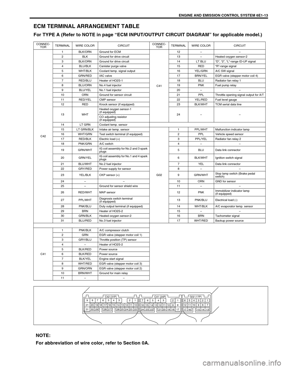
ECM TERMINAL ARRANGEMENT TABLE
For TYPE A (Refer to NOTE in page “ECM INPUT/OUTPUT CIRCUIT DIAGRAM” for applicable model.)
CONNEC-
TORTERMINAL WIRE COLOR CIRCUITCONNEC-
TORTERMINAL WIRE COLOR CIRCUIT
C421 BLK/ORN Ground for ECM
C4112––
2 BLK Ground for drive circuit 13–Heated oxygen sensor-2
3 BLK/ORN Ground for drive circuit 14 LT BLU“D”, “2”, “L”-range ID-UP signal
4 BLU/BLK Canister purge valve 15 RED“R”-range signal
5 WHT/BLK Coolant temp. signal output 16 YEL/GRN A/C SW signal
6 GRN/RED IAC valve 17 BRN/YEL EGR valve (stepper motor coil 4)
7 RED/BLU Heater of HO2S-1 18 BLU Radiator fan relay 1
8 BLU/ORN No.4 fuel injector 19 PNK Fuel pump relay
9 BLU/YEL No.1 fuel injector 20––
10 ORN Ground for sensor circuit 21 PPL Throttle opening signal output for A/T
11 RED/YEL CMP sensor 22 YEL/RED Fuel level gauge
12 RED Knock sensor (if equipped) 23 BLK/WHT TCM serial data line
13 WHTHeated oxygen sensor-1
(if equipped)
24––
CO adjusting resistor
(if equipped)
14 LT GRN Coolant temp. sensor
15 LT GRN/BLK Intake air temp. sensor
G021 PPL/WHT Malfunction indicator lamp
16 WHT/GRN Test switch terminal (if equipped) 2 PPL Vehicle speed sensor
17 RED/BLK Electric load (+) 3 PPL/YEL Radiator fan relay 2
18 PNK/GRN A/C switch 4––
19 GRN/WHTIG coil assembly for No.2 and 3 spark
plugs5 BLU Data link connector
20 GRN/YELIG coil assembly for No.1 and 4 spark
plugs6 BLK/WHT Ignition switch signal
21 BLU/WHT No.2 fuel injector 7 YEL Data link connector
22 GRY/RED Power supply for sensor 8––
23 YEL/BLK CKP sensor (+) 9 GRN/WHTStop lamp switch (Brake pedal
switch)
24––10 ORN GND for sensor
25–Ground for sensor shield wire 11––
26 RED/WHT MAP sensor 12 PNKImmobilizer indicator lamp
(if equipped)
27 PPL/WHTDiagnosis switch terminal
(if equipped)13 PNK/BLU Electrical load (-)
28 PNK/BLU Duty output terminal (if equipped) 14 WHT/BLK A/C evaporator temp. sensor
29 BRN Heater of HO2S-2 15––
30 GRN/BLK Heated oxygen sensor-2 16 BRN Tachometer signal
31 BLU/RED No.3 fuel injector 17 WHT/RED Backup power source
C411 PNK/BLK A/C compressor clutch
2 GRN EGR valve (stepper motor coil 1)
3 GRY/BLU Throttle position (TP) sensor
4–Heater of HO2S-2
5 BLK/RED Power source
6 BLK/RED Power source
7 BLK/YEL Engine start signal
8 WHT/RED EGR valve (stepper motor coil 3)
9 GRN/ORN EGR valve (stepper motor coil 2)
10 BRN/WHT Ground for main relay
11––
C42 (31P) C41 (24P) G02 (17P)1 2 3 4 5 6 7 8 9
10 11 12 13 14 15 16 17 18 19 20 21
22 23 24 25 26 28 27 29 30 315 6
1 2 3 4 5 6 7
11 12
9 10 11 13 12 14 15 16
16 171 2
7 8
13 14 3 4
9 10
15 17 188
19 20 21 22 23 24
NOTE:
For abbreviation of wire color, refer to Section 0A.
Page 635 of 698
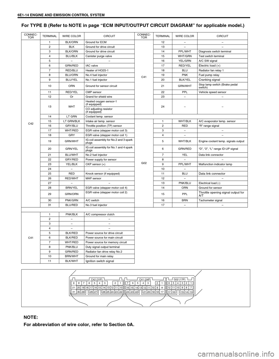
6E1-14 ENGINE AND EMISSION CONTROL SYSTEM
For TYPE B (Refer to NOTE in page “ECM INPUT/OUTPUT CIRCUIT DIAGRAM” for applicable model.)
CONNEC-
TORTERMINAL WIRE COLOR CIRCUITCONNEC-
TORTERMINAL WIRE COLOR CIRCUIT
C421 BLK/ORN Ground for ECM
C4112––
2 BLK Ground for drive circuit 13––
3 BLK/ORN Ground for drive circuit 14 PPL/WHT Diagnosis switch terminal
4 BLU/BLK Canister purge valve 15 WHT/GRN Test switch terminal
5––16 YEL/GRN A/C SW signal
6 GRN/RED IAC valve 17 RED/YEL
Electric load (+)
7 RED/BLU Heater of HO2S-1 18 BLU Radiator fan relay 1
8 BLU/ORN No.4 fuel injector 19 PNK Fuel pump relay
9 BLU/YEL No.1 fuel injector 20 BLK/YEL
Cranking signal
10 ORN Ground for sensor circuit 21 GRN/WHTStop lamp switch (Brake pedal
switch)
11 RED/YEL CMP sensor 22 PPL Vehicle speed sensor
12 Or Grand for shield wire 23––
13 WHTHeated oxygen sensor-1
(if equipped)
24––
CO adjusting resistor
(if equipped)
14 LT GRN Coolant temp. sensor
15 LT GRN/BLK Intake air temp. sensor
G021 WHT/BLK A/C evaporator temp. sensor
16 GRY/BLU Throttle position (TP) sensor 2 RED“R” range signal
17 WHT/RED EGR valve (stepper motor coil 3) 3––
18 GRY EGR valve (stepper motor coil 1) 4––
19 GRN/WHTIG coil assembly for No.2 and 3 spark
plugs5 WHT/BLK Engine coolant temp. signals output
20 GRN/YELIG coil assembly for No.1 and 4 spark
plugs6 GRN/RED“D”, “2”, “L” range ID-UP signal
21 BLU/WHT No.2 fuel injector 7 YEL Data link connector
22 GRY/RED Power supply for sensor 8––
23 YEL/BLK CKP sensor (+) 9 PPL/WHT Malfunction indicator lamp
24––10––
25 RED Knock sensor (if equipped) 11 BLU
Data link connector
26 RED/WHT MAP sensor 12––
27––13 PNK/BLU Electrical load (-)
28 BRN/YEL EGR valve (stepper motor coil 4) 14 ORN Ground for sensor
29 GRN/ORNEGR valve (stepper motor coil 2)
15 PPL
Throttle opening signal output for
A/T
30 PNK/GRN A/C switch 16 BRN Tachometer signal
31 BLU/RED No.3 fuel injector 17––
C411 PNK/BLK A/C compressor clutch
2––
3––
4––
5 BLK/RED Power source for drive circuit
6 BLK/RED Power source for main circuit
7 WHT/RED Power source for memory circuit
8 PNK/BLU Duty signal output terminal
9 GRN/RED Radiator fan drive relay No.2
10 BRN/WHT Ground for main relay
11 BLK/WHT
Ignition switch signal
C42 (31P) C41 (24P) G02 (17P)1 2 3 4 5 6 7 8 9
10 11 12 13 14 15 16 17 18 19 20 21
22 23 24 25 26 28 27 29 30 315 6
1 2 3 4 5 6 7
11 12
9 10 11 13 12 14 15 16
16 171 2
7 8
13 14 3 4
9 10
15 17 188
19 20 21 22 23 24
NOTE:
For abbreviation of wire color, refer to Section 0A.
Page 640 of 698
ENGINE AND EMISSION CONTROL SYSTEM 6E1-19
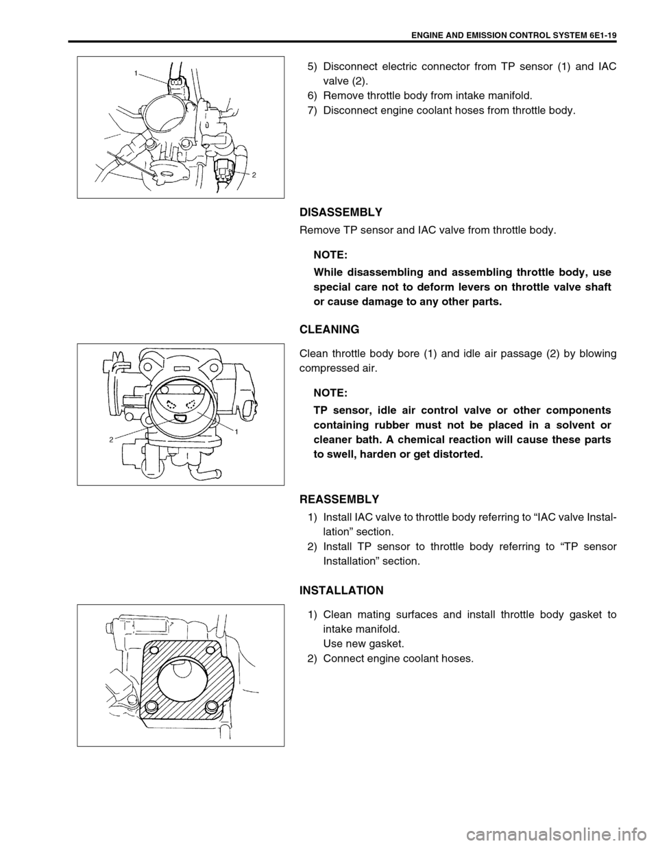
5) Disconnect electric connector from TP sensor (1) and IAC
valve (2).
6) Remove throttle body from intake manifold.
7) Disconnect engine coolant hoses from throttle body.
DISASSEMBLY
Remove TP sensor and IAC valve from throttle body.
CLEANING
Clean throttle body bore (1) and idle air passage (2) by blowing
compressed air.
REASSEMBLY
1) Install IAC valve to throttle body referring to “IAC valve Instal-
lation” section.
2) Install TP sensor to throttle body referring to “TP sensor
Installation” section.
INSTALLATION
1) Clean mating surfaces and install throttle body gasket to
intake manifold.
Use new gasket.
2) Connect engine coolant hoses.
NOTE:
While disassembling and assembling throttle body, use
special care not to deform levers on throttle valve shaft
or cause damage to any other parts.
NOTE:
TP sensor, idle air control valve or other components
containing rubber must not be placed in a solvent or
cleaner bath. A chemical reaction will cause these parts
to swell, harden or get distorted.
Page 655 of 698

6E1-34 ENGINE AND EMISSION CONTROL SYSTEM
FUEL CUT OPERATION
INSPECTION
1) Warm up engine to normal operating temperature.
2) While listening to sound of injector (1) by using sound scope
(2) or such, increase engine speed to higher than 3,000 r/
min.
3) Check to make sure that sound to indicate operation of injec-
tor stops when throttle valve is closed instantly and it is
heard again when engine speed is reduced to less than
about 2,000 r/min.
RADIATOR FAN CONTROL SYSTEM
SYSTEM INSPECTION
Check system for operation referring to Flow Table B-7 in Section
6.
If radiator fan fails to operate properly, check relay, radiator fan
and electrical circuit.
RADIATOR FAN RELAY NO. 2 AND NO.3
INSPECTION
1) Disconnect negative cable at battery.
2) Remove relay(s) from connector(s).NOTE:
Before inspection, check to make sure that gear shift
lever is in neutral position (with A/T model, selector lever
in “P” range), A/C is OFF and that parking brake lever is
pulled all the way up.
WARNING:
Keep hands, tools, and clothing away from engine cool-
ing fan to help prevent personal injury. This fan is electric
and can come on whether or not the engine is running.
The fan can start automatically in response to the ECT
sensor with the ignition switch in the “ON” position.
1. Radiator fan relay No. 2
2. Radiator fan relay No. 3
1
2
Page 664 of 698

6F1-2 IGNITION SYSTEM (ELECTRONIC IGNITION SYSTEM)
GENERAL DESCRIPTION
The ignition system is an electronic (distributorless) ignition system. Its consists of the parts as described below
and has an electronic ignition control system.
ECM
It detects the engine and vehicle conditions through the signals from the sensors, determines the most suit-
able ignition timing and time for electricity to flow to the primary coil and sends a signal to the ignitor (power
unit) in the ignition coil assembly.
Ignition coil assembly (including an igniter)
The ignition coil assembly has a built-in ignitor which turns ON and OFF the current flow to the primary coil
according to the signal from ECM. When the current flow to the primary coil is turned OFF, a high voltage is
induced in the secondary coil.
High tension cords and spark plugs.
CMP sensor (Camshaft position sensor) and CKP sensor (Crankshaft position sensor)
Using signals from these sensors, ECM identifies the specific cylinder whose piston is in the compression
stroke, detects the crank angle and adjusts initial ignition timing automatically.
TP sensor, ECT sensor, MAP sensor and other sensors/switches
Refer to Section 6E1 for details.
Although this ignition system does not have a distributor, it has two ignition coil assemblies (one is for No.1 and
No.4 spark plugs and the other is for No.2 and No.3 spark plugs). When an ignition signal is sent from ECM to
the ignitor in the ignition coil assembly for No.1 and No.4 spark plugs, a high voltage is induced in the secondary
coil and that passes through the high-tension cords and causes No.1 and No.4 spark plugs to spark simulta-
neously. Likewise, when an ignition signal is sent to the ignitor in the other ignition coil assembly, No.2 and No.3
spark plugs spark simultaneously.
SYSTEM COMPONENTS
1. ECM 6. MAP sensor 11. Transmission range switch (A/T)
2. Ignition coil assembly for No.1 and No.4 spark plugs 7. ECT sensor 12. High-tension cords
3. Ignition coil assembly for No.2 and No.3 spark plugs 8. IAT sensor 13. Monitor connector
4. CMP sensor 9. TP sensor 14. Knock sensor (if equipped)
5. CKP sensor 10. VSS 15. Data link connector
Page 665 of 698

IGNITION SYSTEM (ELECTRONIC IGNITION SYSTEM 6F1-3
SYSTEM WIRING DIAGRAM
DIAGNOSIS
1. Ignition switch 7. No.1 spark plug
2. Main relay 8. No.2 spark plug
3. Ignition coil assembly for No.1 and No.4 spark plugs 9. No.3 spark plug
4. Ignition coil assembly for No.2 and No.3 spark plugs 10. No.4 spark plug
5. CMP sensor 11. Sensed information (MAP sensor, ECT sensor, IAT sensor, TP sensor, Knock sensor (if
equipped), VSS, Park/Neutral position signal, Electric load signal, Engine start signal, Test switch
terminal (Vehicle without immobilizer indicator lamp))
6. CKP sensor
Condition Possible Cause Correction
Engine cranks, but will
not start or hard to
start (No spark)Blown fuse for ignition coil Replace.
Loose connection or disconnection of lead wire
or high-tension cord(s)Connect securely.
Faulty high-tension cord(s) Replace.
Faulty spark plug(s) Adjust, clean or replace.
Faulty ignition coil Replace ignition coil assembly.
Faulty CKP sensor or CKP sensor plate Clean, tighten or replace.
Faulty ECM Replace.
Poor fuel economy or
engine performanceIncorrect ignition timing Check related sensors and CKP
sensor plate.
Faulty spark plug(s) or high-tension cord(s) Adjust, clean or replace.
Faulty ignition coil assembly Replace.
Faulty CKP sensor or CKP sensor plate Clean, tighten or replace.
Faulty ECM Replace.