oil SUZUKI SWIFT 2000 1.G RG413 Service Owners Manual
[x] Cancel search | Manufacturer: SUZUKI, Model Year: 2000, Model line: SWIFT, Model: SUZUKI SWIFT 2000 1.GPages: 698, PDF Size: 16.01 MB
Page 296 of 698
BRAKES 5-23
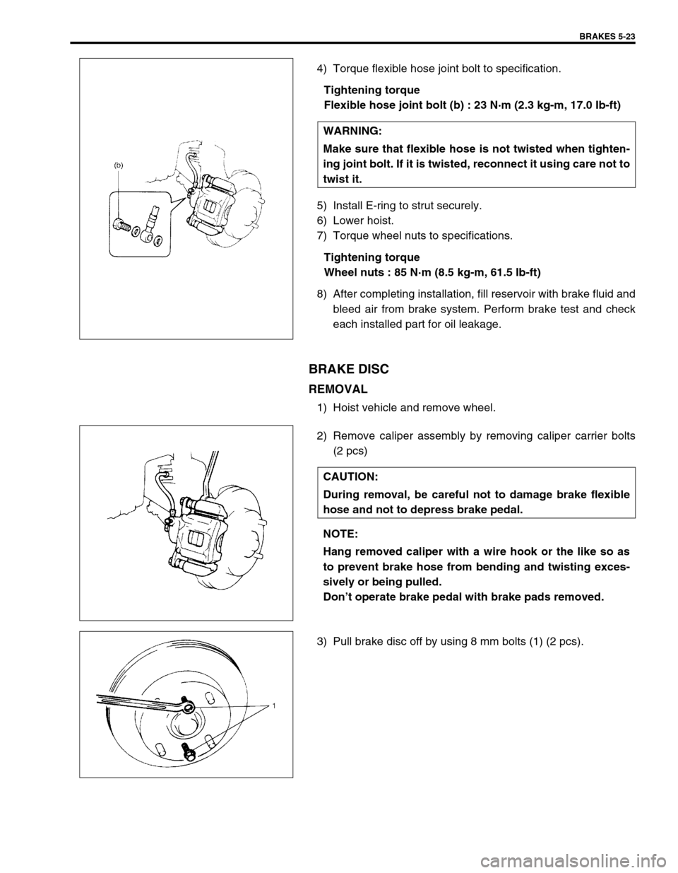
4) Torque flexible hose joint bolt to specification.
Tightening torque
Flexible hose joint bolt (b) : 23 N·m (2.3 kg-m, 17.0 Ib-ft)
5) Install E-ring to strut securely.
6) Lower hoist.
7) Torque wheel nuts to specifications.
Tightening torque
Wheel nuts : 85 N·m (8.5 kg-m, 61.5 Ib-ft)
8) After completing installation, fill reservoir with brake fluid and
bleed air from brake system. Perform brake test and check
each installed part for oil leakage.
BRAKE DISC
REMOVAL
1) Hoist vehicle and remove wheel.
2) Remove caliper assembly by removing caliper carrier bolts
(2 pcs)
3) Pull brake disc off by using 8 mm bolts (1) (2 pcs).WARNING:
Make sure that flexible hose is not twisted when tighten-
ing joint bolt. If it is twisted, reconnect it using care not to
twist it.
CAUTION:
During removal, be careful not to damage brake flexible
hose and not to depress brake pedal.
NOTE:
Hang removed caliper with a wire hook or the like so as
to prevent brake hose from bending and twisting exces-
sively or being pulled.
Don’t operate brake pedal with brake pads removed.
Page 300 of 698
BRAKES 5-27
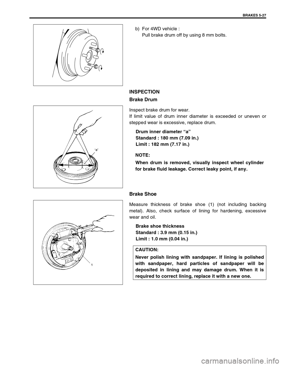
b) For 4WD vehicle :
Pull brake drum off by using 8 mm bolts.
INSPECTION
Brake Drum
Inspect brake drum for wear.
If limit value of drum inner diameter is exceeded or uneven or
stepped wear is excessive, replace drum.
Drum inner diameter “a”
Standard : 180 mm (7.09 in.)
Limit : 182 mm (7.17 in.)
Brake Shoe
Measure thickness of brake shoe (1) (not including backing
metal). Also, check surface of lining for hardening, excessive
wear and oil.
Brake shoe thickness
Standard : 3.9 mm (0.15 in.)
Limit : 1.0 mm (0.04 in.)
NOTE:
When drum is removed, visually inspect wheel cylinder
for brake fluid leakage. Correct leaky point, if any.
CAUTION:
Never polish lining with sandpaper. If lining is polished
with sandpaper, hard particles of sandpaper will be
deposited in lining and may damage drum. When it is
required to correct lining, replace it with a new one.
Page 301 of 698
5-28 BRAKES
INSTALLATION
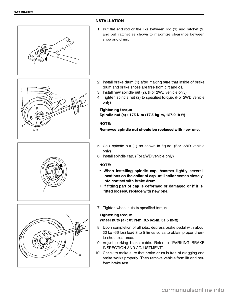
1) Put flat end rod or the like between rod (1) and ratchet (2)
and pull ratchet as shown to maximize clearance between
shoe and drum.
2) Install brake drum (1) after making sure that inside of brake
drum and brake shoes are free from dirt and oil.
3) Install new spindle nut (2). (For 2WD vehicle only)
4) Tighten spindle nut (2) to specified torque. (For 2WD vehicle
only)
Tightening torque
Spindle nut (a) : 175 N·m (17.5 kg-m, 127.0 lb-ft)
5) Calk spindle nut (1) as shown in figure. (For 2WD vehicle
only)
6) Install spindle cap. (For 2WD vehicle only)
7) Tighten wheel nuts to specified torque.
Tightening torque
Wheel nuts (a) : 85 N·m (8.5 kg-m, 61.5 lb-ft)
8) Upon completion of all jobs, depress brake pedal with about
30 kg (66 lbs) load 3 to 5 times so as to obtain proper drum-
to-shoe clearance.
9) Adjust parking brake cable. Refer to “PARKING BRAKE
INSPECTION AND ADJUSTMENT”.
10) Check to make sure that brake drum is free of dragging and
brake works properly. Then remove vehicle from lift and per-
form brake test.
NOTE:
Removed spindle nut should be replaced with new one.
NOTE:
When installing spindle cap, hammer lightly several
locations on the collar of cap until collar comes closely
into contact with brake drum.
If fitting part of cap is deformed or damaged or if it is
fitted loosely, replace with new one.
Page 304 of 698
BRAKES 5-31
INSTALLATION
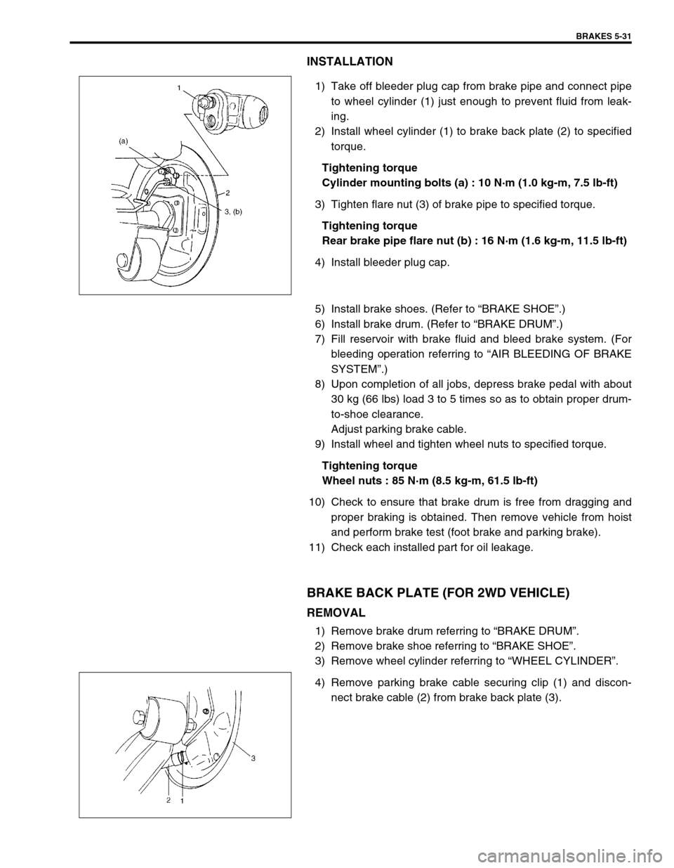
1) Take off bleeder plug cap from brake pipe and connect pipe
to wheel cylinder (1) just enough to prevent fluid from leak-
ing.
2) Install wheel cylinder (1) to brake back plate (2) to specified
torque.
Tightening torque
Cylinder mounting bolts (a) : 10 N·m (1.0 kg-m, 7.5 lb-ft)
3) Tighten flare nut (3) of brake pipe to specified torque.
Tightening torque
Rear brake pipe flare nut (b) : 16 N·m (1.6 kg-m, 11.5 lb-ft)
4) Install bleeder plug cap.
5) Install brake shoes. (Refer to “BRAKE SHOE”.)
6) Install brake drum. (Refer to “BRAKE DRUM”.)
7) Fill reservoir with brake fluid and bleed brake system. (For
bleeding operation referring to “AIR BLEEDING OF BRAKE
SYSTEM”.)
8) Upon completion of all jobs, depress brake pedal with about
30 kg (66 lbs) load 3 to 5 times so as to obtain proper drum-
to-shoe clearance.
Adjust parking brake cable.
9) Install wheel and tighten wheel nuts to specified torque.
Tightening torque
Wheel nuts : 85 N·m (8.5 kg-m, 61.5 lb-ft)
10) Check to ensure that brake drum is free from dragging and
proper braking is obtained. Then remove vehicle from hoist
and perform brake test (foot brake and parking brake).
11) Check each installed part for oil leakage.
BRAKE BACK PLATE (FOR 2WD VEHICLE)
REMOVAL
1) Remove brake drum referring to “BRAKE DRUM”.
2) Remove brake shoe referring to “BRAKE SHOE”.
3) Remove wheel cylinder referring to “WHEEL CYLINDER”.
4) Remove parking brake cable securing clip (1) and discon-
nect brake cable (2) from brake back plate (3).
Page 308 of 698
BRAKES 5-35
INSPECTION
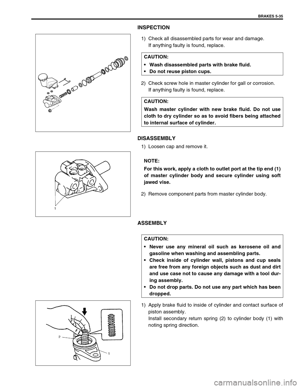
1) Check all disassembled parts for wear and damage.
If anything faulty is found, replace.
2) Check screw hole in master cylinder for gall or corrosion.
If anything faulty is found, replace.
DISASSEMBLY
1) Loosen cap and remove it.
2) Remove component parts from master cylinder body.
ASSEMBLY
1) Apply brake fluid to inside of cylinder and contact surface of
piston assembly.
Install secondary return spring (2) to cylinder body (1) with
noting spring direction. CAUTION:
Wash disassembled parts with brake fluid.
Do not reuse piston cups.
CAUTION:
Wash master cylinder with new brake fluid. Do not use
cloth to dry cylinder so as to avoid fibers being attached
to internal surface of cylinder.
NOTE:
For this work, apply a cloth to outlet port at the tip end (1)
of master cylinder body and secure cylinder using soft
jawed vise.
CAUTION:
Never use any mineral oil such as kerosene oil and
gasoline when washing and assembling parts.
Check inside of cylinder wall, pistons and cup seals
are free from any foreign objects such as dust and dirt
and use case not to cause any damage with a tool dur-
ing assembly.
Do not drop parts. Do not use any part which has been
dropped.
Page 311 of 698
5-38 BRAKES
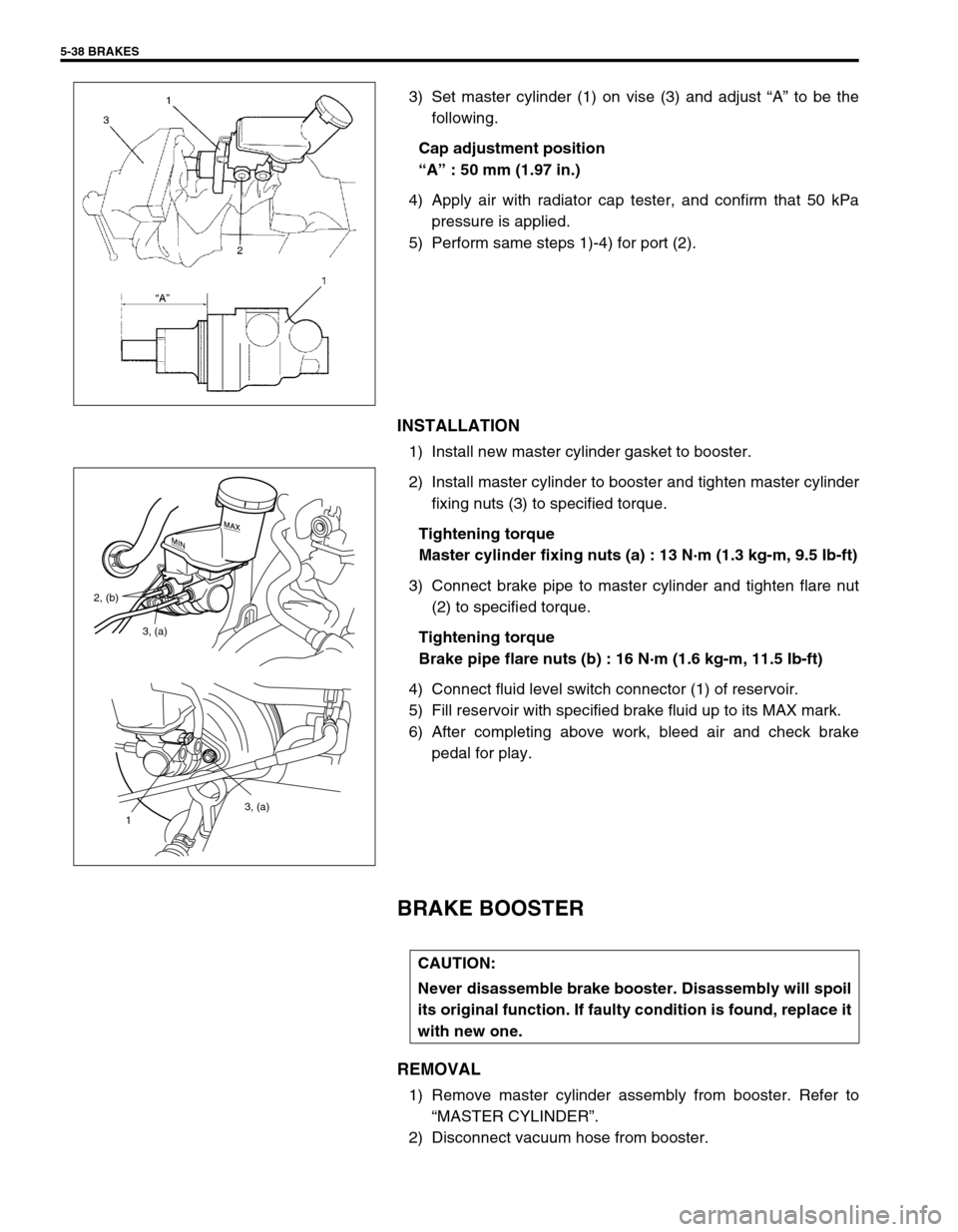
3) Set master cylinder (1) on vise (3) and adjust “A” to be the
following.
Cap adjustment position
“A” : 50 mm (1.97 in.)
4) Apply air with radiator cap tester, and confirm that 50 kPa
pressure is applied.
5) Perform same steps 1)-4) for port (2).
INSTALLATION
1) Install new master cylinder gasket to booster.
2) Install master cylinder to booster and tighten master cylinder
fixing nuts (3) to specified torque.
Tightening torque
Master cylinder fixing nuts (a) : 13 N·m (1.3 kg-m, 9.5 Ib-ft)
3) Connect brake pipe to master cylinder and tighten flare nut
(2) to specified torque.
Tightening torque
Brake pipe flare nuts (b) : 16 N·m (1.6 kg-m, 11.5 Ib-ft)
4) Connect fluid level switch connector (1) of reservoir.
5) Fill reservoir with specified brake fluid up to its MAX mark.
6) After completing above work, bleed air and check brake
pedal for play.
BRAKE BOOSTER
REMOVAL
1) Remove master cylinder assembly from booster. Refer to
“MASTER CYLINDER”.
2) Disconnect vacuum hose from booster.
3, (a)
1
3, (a) 2, (b)
CAUTION:
Never disassemble brake booster. Disassembly will spoil
its original function. If faulty condition is found, replace it
with new one.
Page 321 of 698
5-48 BRAKES
LSPV (LOAD SENSING PROPORTIONING VALVE) ASSEMBLY (IF EQUIPPED)
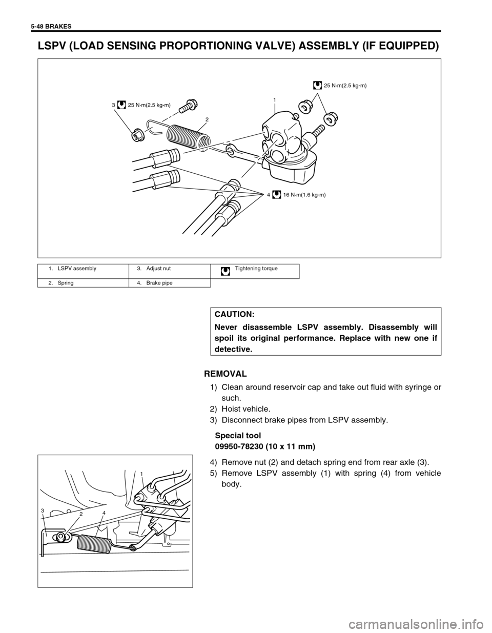
REMOVAL
1) Clean around reservoir cap and take out fluid with syringe or
such.
2) Hoist vehicle.
3) Disconnect brake pipes from LSPV assembly.
Special tool
09950-78230 (10 x 11 mm)
4) Remove nut (2) and detach spring end from rear axle (3).
5) Remove LSPV assembly (1) with spring (4) from vehicle
body.
1. LSPV assembly 3. Adjust nut Tightening torque
2. Spring 4. Brake pipe
CAUTION:
Never disassemble LSPV assembly. Disassembly will
spoil its original performance. Replace with new one if
detective.
3
21
25 N·m(2.5 kg-m)
4 16 N·m(1.6 kg-m)
25 N·m(2.5 kg-m)
3
24
1
Page 322 of 698
BRAKES 5-49
INSTALLATION
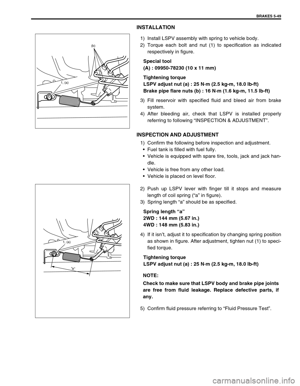
1) Install LSPV assembly with spring to vehicle body.
2) Torque each bolt and nut (1) to specification as indicated
respectively in figure.
Special tool
(A) : 09950-78230 (10 x 11 mm)
Tightening torque
LSPV adjust nut (a) : 25 N·m (2.5 kg-m, 18.0 lb-ft)
Brake pipe flare nuts (b) : 16 N·m (1.6 kg-m, 11.5 lb-ft)
3) Fill reservoir with specified fluid and bleed air from brake
system.
4) After bleeding air, check that LSPV is installed properly
referring to following “INSPECTION & ADJUSTMENT”.
INSPECTION AND ADJUSTMENT
1) Confirm the following before inspection and adjustment.
Fuel tank is filled with fuel fully.
Vehicle is equipped with spare tire, tools, jack and jack han-
dle.
Vehicle is free from any other load.
Vehicle is placed on level floor.
2) Push up LSPV lever with finger till it stops and measure
length of coil spring (“a” in figure).
3) Spring length “a” should be as specified.
Spring length “a”
2WD : 144 mm (5.67 in.)
4WD : 148 mm (5.83 in.)
4) If it isn’t, adjust it to specification by changing spring position
as shown in figure. After adjustment, tighten nut (1) to speci-
fied torque.
Tightening torque
LSPV adjust nut (a) : 25 N·m (2.5 kg-m, 18.0 lb-ft)
5) Confirm fluid pressure referring to “Fluid Pressure Test”.
1, (a)
(b)
NOTE:
Check to make sure that LSPV body and brake pipe joints
are free from fluid leakage. Replace defective parts, if
any.
1, (a)
“a”
Page 373 of 698
6-4 ENGINE GENERAL INFORMATION AND DIAGNOSIS
GENERAL INFORMATION
STATEMENT ON CLEANLINESS AND CARE
An automobile engine is a combination of many machined, honed, polished and lapped surfaces with tolerances
that are measured in the thousands of an millimeter (ten thousands of an inch).
Accordingly, when any internal engine parts are serviced, care and cleanliness are important.
Throughout this section, it should be understood that proper cleaning and protection of machined surfaces and
friction areas is part of the repair procedure. This is considered standard shop practice even if not specifically
stated.
A liberal coating of engine oil should be applied to friction areas during assembly to protect and lubricate the
surfaces on initial operation.
Whenever valve train components, pistons, piston rings, connecting rods, rod bearings, and crankshaft jour-
nal bearings are removed for service, they should be retained in order.
At the time of installation, they should be installed in the same locations and with the same mating surfaces
as when removed.
Battery cables should be disconnected before any major work is performed on the engine.
Failure to disconnect cables may result in damage to wire harness or other electrical parts.
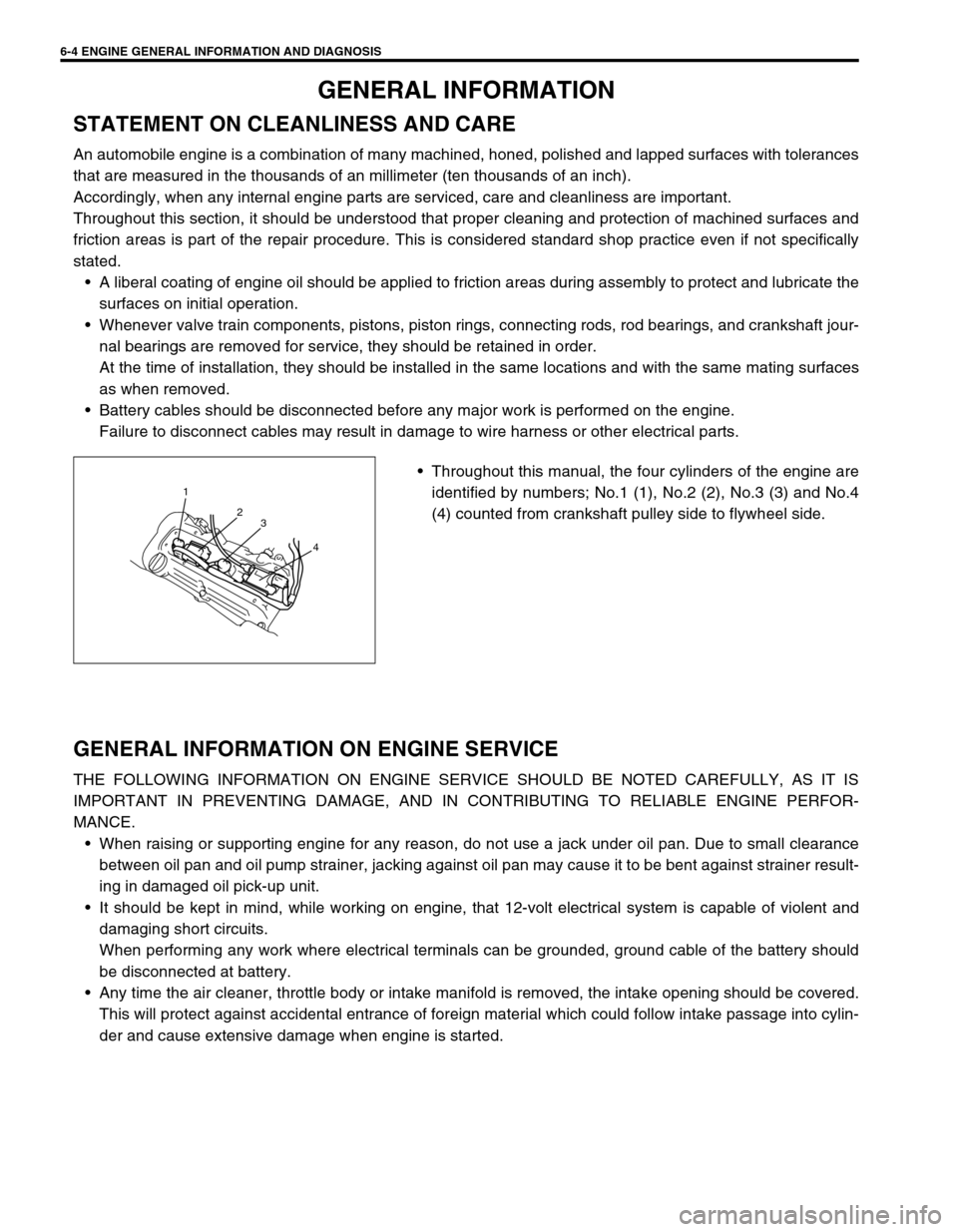
Throughout this manual, the four cylinders of the engine are
identified by numbers; No.1 (1), No.2 (2), No.3 (3) and No.4
(4) counted from crankshaft pulley side to flywheel side.
GENERAL INFORMATION ON ENGINE SERVICE
THE FOLLOWING INFORMATION ON ENGINE SERVICE SHOULD BE NOTED CAREFULLY, AS IT IS
IMPORTANT IN PREVENTING DAMAGE, AND IN CONTRIBUTING TO RELIABLE ENGINE PERFOR-
MANCE.
When raising or supporting engine for any reason, do not use a jack under oil pan. Due to small clearance
between oil pan and oil pump strainer, jacking against oil pan may cause it to be bent against strainer result-
ing in damaged oil pick-up unit.
It should be kept in mind, while working on engine, that 12-volt electrical system is capable of violent and
damaging short circuits.
When performing any work where electrical terminals can be grounded, ground cable of the battery should
be disconnected at battery.
Any time the air cleaner, throttle body or intake manifold is removed, the intake opening should be covered.
This will protect against accidental entrance of foreign material which could follow intake passage into cylin-
der and cause extensive damage when engine is started.
1
2
3
4
Page 374 of 698
ENGINE GENERAL INFORMATION AND DIAGNOSIS 6-5
PRECAUTION ON FUEL SYSTEM SERVICE
Work must be done with no smoking, in a well-ventilated
area and away from any open flames.
As fuel feed line (between fuel pump and fuel delivery pipe)
is still under high fuel pressure even after engine was
stopped, loosening or disconnecting fuel feed line directly
may cause dangerous spout of fuel to occur where loosened
or disconnected.
Before loosening or disconnecting fuel feed line, make sure
to release fuel pressure according to “FUEL PRESSURE
RELIEF PROCEDURE”. A small amount of fuel may be
released after the fuel line is disconnected. In order to
reduce the chance of personal injury, cover the fitting to be
disconnected with a shop cloth. Put that cloth in an approved
container when disconnection is completed.
Never run engine with fuel pump relay disconnected when
engine and exhaust system are hot.
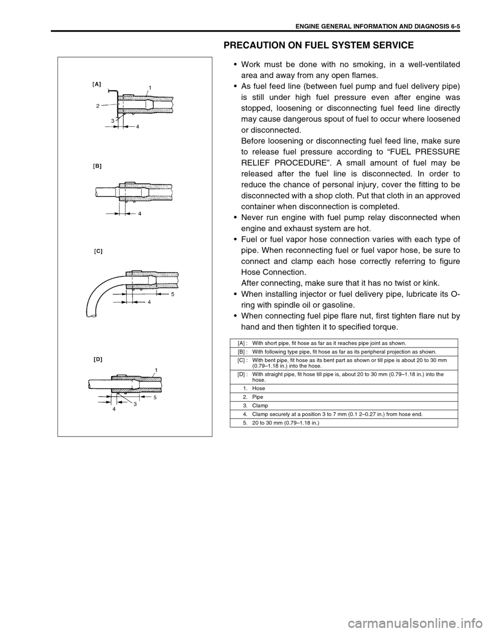
Fuel or fuel vapor hose connection varies with each type of
pipe. When reconnecting fuel or fuel vapor hose, be sure to
connect and clamp each hose correctly referring to figure
Hose Connection.
After connecting, make sure that it has no twist or kink.
When installing injector or fuel delivery pipe, lubricate its O-
ring with spindle oil or gasoline.
When connecting fuel pipe flare nut, first tighten flare nut by
hand and then tighten it to specified torque.
[A] : With short pipe, fit hose as far as it reaches pipe joint as shown.
[B] : With following type pipe, fit hose as far as its peripheral projection as shown.
[C] : With bent pipe, fit hose as its bent part as shown or till pipe is about 20 to 30 mm
(0.79–1.18 in.) into the hose.
[D] : With straight pipe, fit hose till pipe is, about 20 to 30 mm (0.79–1.18 in.) into the
hose.
1. Hose
2. Pipe
3. Clamp
4. Clamp securely at a position 3 to 7 mm (0.1 2–0.27 in.) from hose end.
5. 20 to 30 mm (0.79–1.18 in.)