sensor SUZUKI SWIFT 2000 1.G RG413 Service Repair Manual
[x] Cancel search | Manufacturer: SUZUKI, Model Year: 2000, Model line: SWIFT, Model: SUZUKI SWIFT 2000 1.GPages: 698, PDF Size: 16.01 MB
Page 350 of 698
ANTILOCK BRAKE SYSTEM (ABS) 5E-25
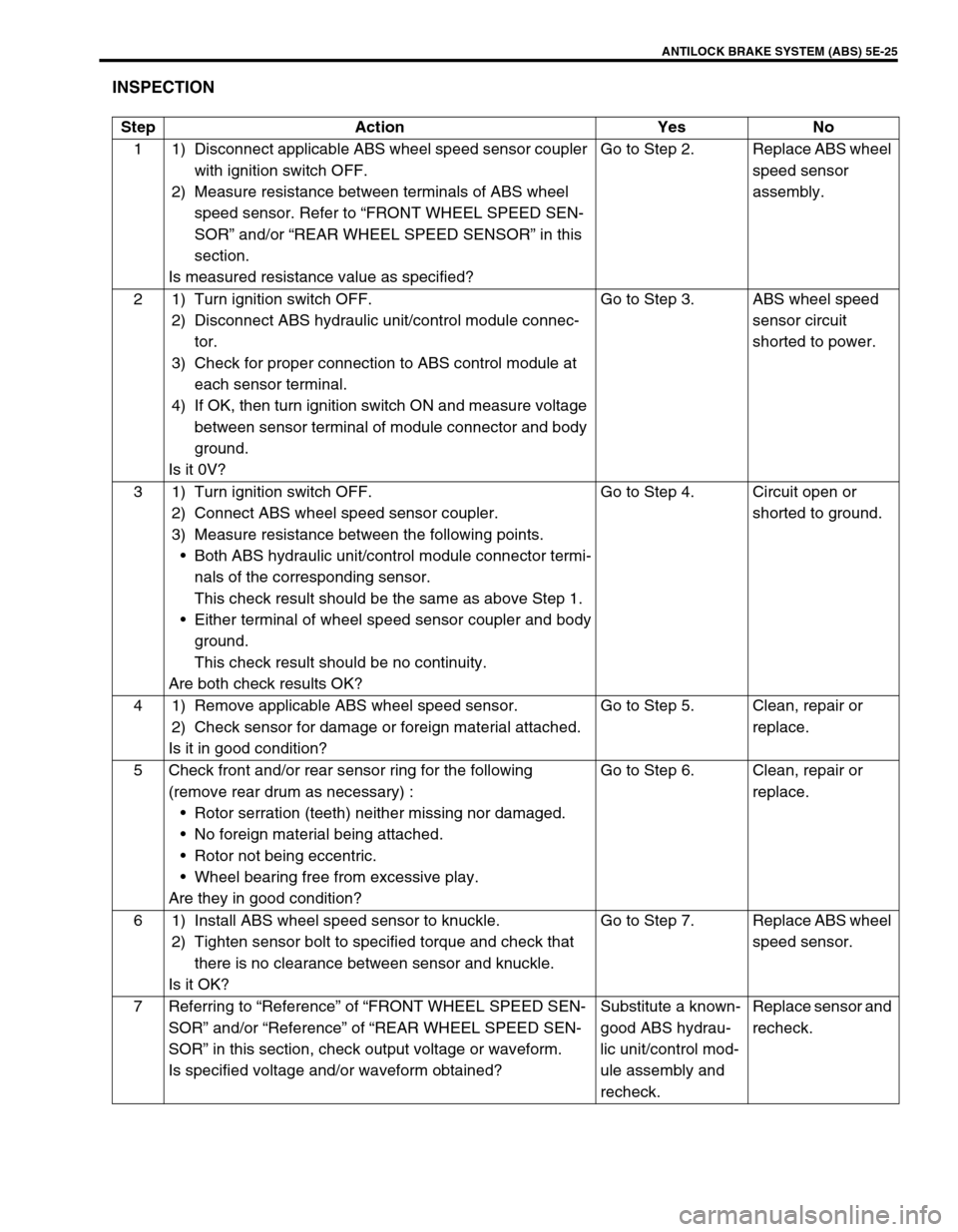
INSPECTION
Step Action Yes No
1 1) Disconnect applicable ABS wheel speed sensor coupler
with ignition switch OFF.
2) Measure resistance between terminals of ABS wheel
speed sensor. Refer to “FRONT WHEEL SPEED SEN-
SOR” and/or “REAR WHEEL SPEED SENSOR” in this
section.
Is measured resistance value as specified?Go to Step 2. Replace ABS wheel
speed sensor
assembly.
2 1) Turn ignition switch OFF.
2) Disconnect ABS hydraulic unit/control module connec-
tor.
3) Check for proper connection to ABS control module at
each sensor terminal.
4) If OK, then turn ignition switch ON and measure voltage
between sensor terminal of module connector and body
ground.
Is it 0V?Go to Step 3. ABS wheel speed
sensor circuit
shorted to power.
3 1) Turn ignition switch OFF.
2) Connect ABS wheel speed sensor coupler.
3) Measure resistance between the following points.
Both ABS hydraulic unit/control module connector termi-
nals of the corresponding sensor.
This check result should be the same as above Step 1.
Either terminal of wheel speed sensor coupler and body
ground.
This check result should be no continuity.
Are both check results OK?Go to Step 4. Circuit open or
shorted to ground.
4 1) Remove applicable ABS wheel speed sensor.
2) Check sensor for damage or foreign material attached.
Is it in good condition?Go to Step 5. Clean, repair or
replace.
5 Check front and/or rear sensor ring for the following
(remove rear drum as necessary) :
Rotor serration (teeth) neither missing nor damaged.
No foreign material being attached.
Rotor not being eccentric.
Wheel bearing free from excessive play.
Are they in good condition?Go to Step 6. Clean, repair or
replace.
6 1) Install ABS wheel speed sensor to knuckle.
2) Tighten sensor bolt to specified torque and check that
there is no clearance between sensor and knuckle.
Is it OK?Go to Step 7. Replace ABS wheel
speed sensor.
7 Referring to “Reference” of “FRONT WHEEL SPEED SEN-
SOR” and/or “Reference” of “REAR WHEEL SPEED SEN-
SOR” in this section, check output voltage or waveform.
Is specified voltage and/or waveform obtained?Substitute a known-
good ABS hydrau-
lic unit/control mod-
ule assembly and
recheck.Replace sensor and
recheck.
Page 356 of 698
ANTILOCK BRAKE SYSTEM (ABS) 5E-31
ON-VEHICLE SERVICE
PRECAUTIONS
When connector is connected to ABS hydraulic unit/control mod-
ule assembly, do not disconnect connectors of sensors with igni-
tion switch ON. Then DTC will be set in ABS control module.
ABS HYDRAULIC UNIT OPERATION CHECK
(USING SUZUKI SCAN TOOL)
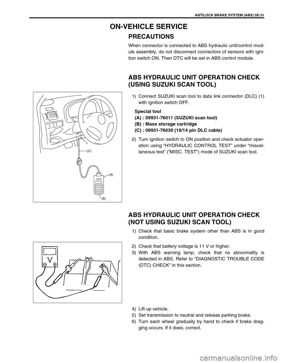
1) Connect SUZUKI scan tool to data link connector (DLC) (1)
with ignition switch OFF.
Special tool
(A) : 09931-76011 (SUZUKI scan tool)
(B) : Mass storage cartridge
(C) : 09931-76030 (16/14 pin DLC cable)
2) Turn ignition switch to ON position and check actuator oper-
ation using “HYDRAULIC CONTROL TEST” under “miscel-
laneous test” (“MISC. TEST”) mode of SUZUKI scan tool.
ABS HYDRAULIC UNIT OPERATION CHECK
(NOT USING SUZUKI SCAN TOOL)
1) Check that basic brake system other than ABS is in good
condition.
2) Check that battery voltage is 11 V or higher.
3) With ABS warning lamp, check that no abnormality is
detected in ABS. Refer to “DIAGNOSTIC TROUBLE CODE
(DTC) CHECK” in this section.
4) Lift up vehicle.
5) Set transmission to neutral and release parking brake.
6) Turn each wheel gradually by hand to check if brake drag-
ging occurs. If it does, correct.
(A)
(B) (C) 1
Page 360 of 698
ANTILOCK BRAKE SYSTEM (ABS) 5E-35
FRONT WHEEL SPEED SENSOR
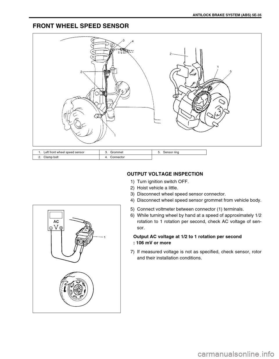
OUTPUT VOLTAGE INSPECTION
1) Turn ignition switch OFF.
2) Hoist vehicle a little.
3) Disconnect wheel speed sensor connector.
4) Disconnect wheel speed sensor grommet from vehicle body.
5) Connect voltmeter between connector (1) terminals.
6) While turning wheel by hand at a speed of approximately 1/2
rotation to 1 rotation per second, check AC voltage of sen-
sor.
Output AC voltage at 1/2 to 1 rotation per second
: 106 mV or more
7) If measured voltage is not as specified, check sensor, rotor
and their installation conditions.
1. Left front wheel speed sensor 3. Grommet 5. Sensor ring
2. Clamp bolt 4. Connector
Page 361 of 698
5E-36 ANTILOCK BRAKE SYSTEM (ABS)
Reference
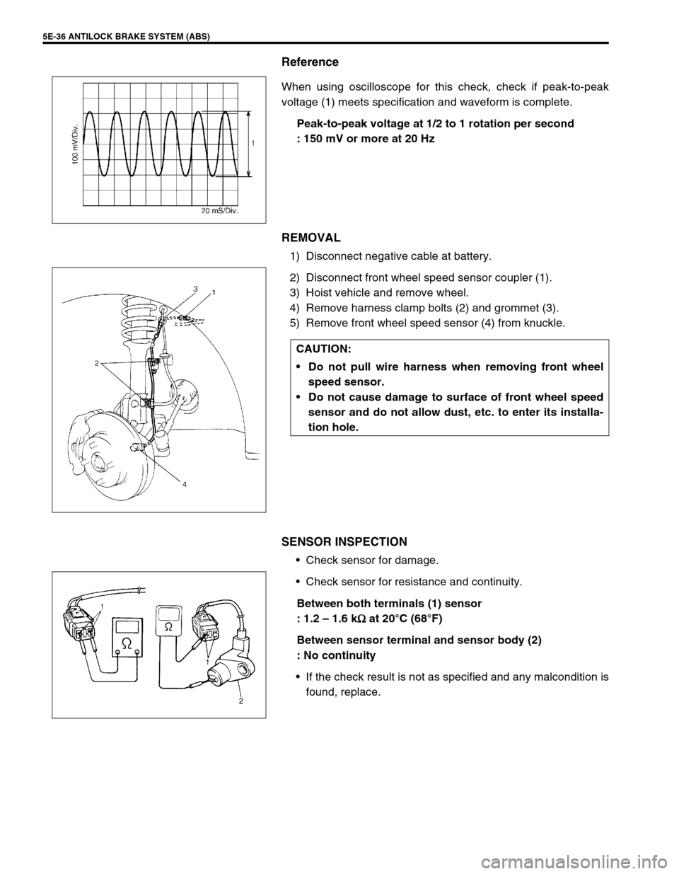
When using oscilloscope for this check, check if peak-to-peak
voltage (1) meets specification and waveform is complete.
Peak-to-peak voltage at 1/2 to 1 rotation per second
: 150 mV or more at 20 Hz
REMOVAL
1) Disconnect negative cable at battery.
2) Disconnect front wheel speed sensor coupler (1).
3) Hoist vehicle and remove wheel.
4) Remove harness clamp bolts (2) and grommet (3).
5) Remove front wheel speed sensor (4) from knuckle.
SENSOR INSPECTION
Check sensor for damage.
Check sensor for resistance and continuity.
Between both terminals (1) sensor
: 1.2 – 1.6 k
Ω
ΩΩ Ω at 20°C (68°F)
Between sensor terminal and sensor body (2)
: No continuity
If the check result is not as specified and any malcondition is
found, replace.
CAUTION:
Do not pull wire harness when removing front wheel
speed sensor.
Do not cause damage to surface of front wheel speed
sensor and do not allow dust, etc. to enter its installa-
tion hole.
Page 362 of 698
ANTILOCK BRAKE SYSTEM (ABS) 5E-37
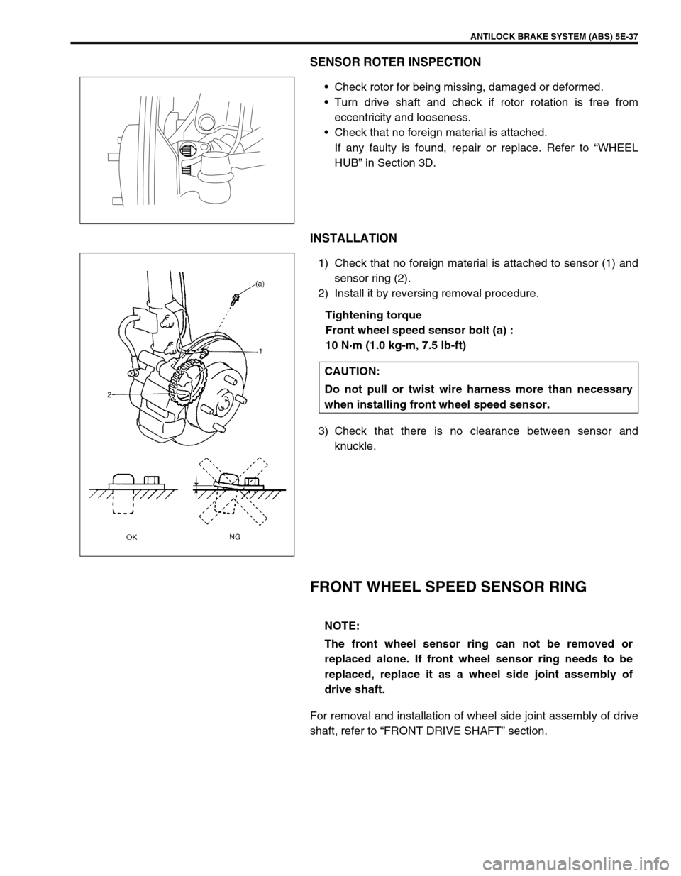
SENSOR ROTER INSPECTION
Check rotor for being missing, damaged or deformed.
Turn drive shaft and check if rotor rotation is free from
eccentricity and looseness.
Check that no foreign material is attached.
If any faulty is found, repair or replace. Refer to “WHEEL
HUB” in Section 3D.
INSTALLATION
1) Check that no foreign material is attached to sensor (1) and
sensor ring (2).
2) Install it by reversing removal procedure.
Tightening torque
Front wheel speed sensor bolt (a) :
10 N·m (1.0 kg-m, 7.5 lb-ft)
3) Check that there is no clearance between sensor and
knuckle.
FRONT WHEEL SPEED SENSOR RING
For removal and installation of wheel side joint assembly of drive
shaft, refer to “FRONT DRIVE SHAFT” section.
CAUTION:
Do not pull or twist wire harness more than necessary
when installing front wheel speed sensor.
NOTE:
The front wheel sensor ring can not be removed or
replaced alone. If front wheel sensor ring needs to be
replaced, replace it as a wheel side joint assembly of
drive shaft.
Page 363 of 698
5E-38 ANTILOCK BRAKE SYSTEM (ABS)
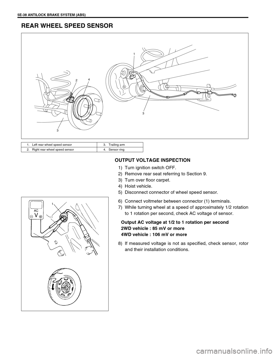
REAR WHEEL SPEED SENSOR
OUTPUT VOLTAGE INSPECTION
1) Turn ignition switch OFF.
2) Remove rear seat referring to Section 9.
3) Turn over floor carpet.
4) Hoist vehicle.
5) Disconnect connector of wheel speed sensor.
6) Connect voltmeter between connector (1) terminals.
7) While turning wheel at a speed of approximately 1/2 rotation
to 1 rotation per second, check AC voltage of sensor.
Output AC voltage at 1/2 to 1 rotation per second
2WD vehicle : 85 mV or more
4WD vehicle : 106 mV or more
8) If measured voltage is not as specified, check sensor, rotor
and their installation conditions.
1. Left rear wheel speed sensor 3. Trailing arm
2. Right rear wheel speed sensor 4. Sensor ring
3 1
4
2
3
Page 364 of 698
ANTILOCK BRAKE SYSTEM (ABS) 5E-39
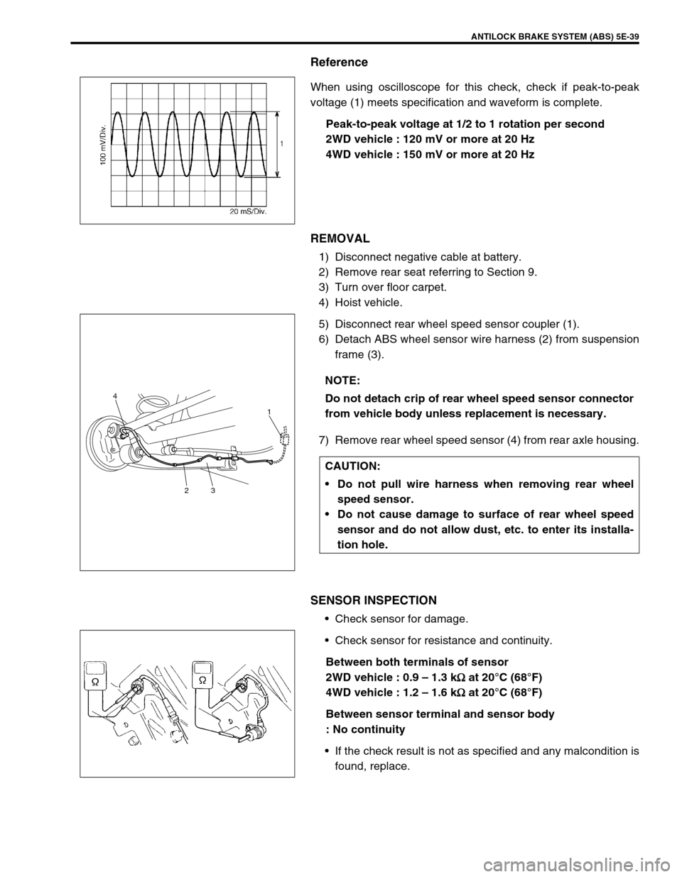
Reference
When using oscilloscope for this check, check if peak-to-peak
voltage (1) meets specification and waveform is complete.
Peak-to-peak voltage at 1/2 to 1 rotation per second
2WD vehicle : 120 mV or more at 20 Hz
4WD vehicle : 150 mV or more at 20 Hz
REMOVAL
1) Disconnect negative cable at battery.
2) Remove rear seat referring to Section 9.
3) Turn over floor carpet.
4) Hoist vehicle.
5) Disconnect rear wheel speed sensor coupler (1).
6) Detach ABS wheel sensor wire harness (2) from suspension
frame (3).
7) Remove rear wheel speed sensor (4) from rear axle housing.
SENSOR INSPECTION
Check sensor for damage.
Check sensor for resistance and continuity.
Between both terminals of sensor
2WD vehicle : 0.9 – 1.3 k
Ω
ΩΩ Ω at 20°C (68°F)
4WD vehicle : 1.2 – 1.6 k
Ω
ΩΩ Ω at 20°C (68°F)
Between sensor terminal and sensor body
: No continuity
If the check result is not as specified and any malcondition is
found, replace.
NOTE:
Do not detach crip of rear wheel speed sensor connector
from vehicle body unless replacement is necessary.
CAUTION:
Do not pull wire harness when removing rear wheel
speed sensor.
Do not cause damage to surface of rear wheel speed
sensor and do not allow dust, etc. to enter its installa-
tion hole.
4
231
Page 365 of 698
5E-40 ANTILOCK BRAKE SYSTEM (ABS)
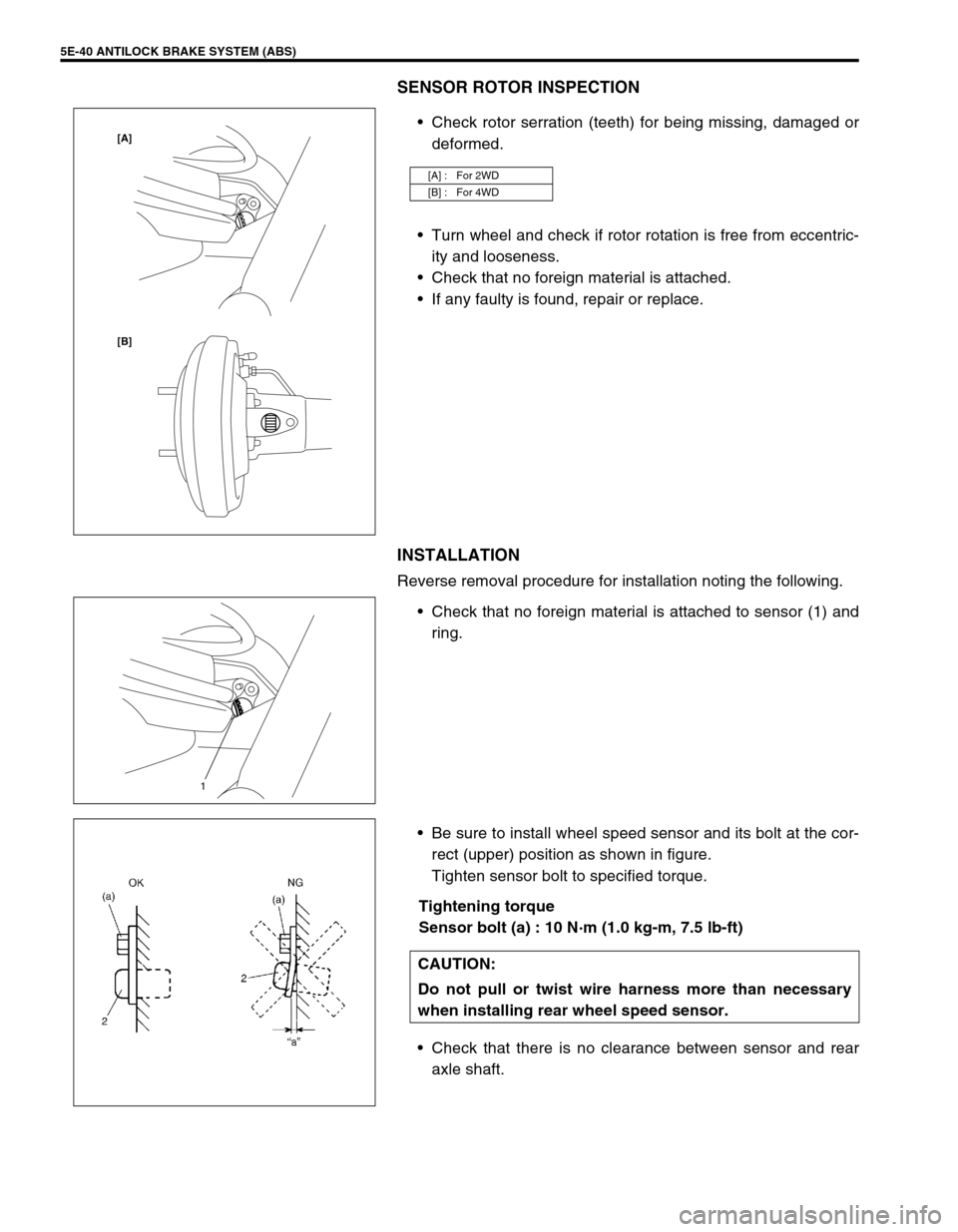
SENSOR ROTOR INSPECTION
Check rotor serration (teeth) for being missing, damaged or
deformed.
Turn wheel and check if rotor rotation is free from eccentric-
ity and looseness.
Check that no foreign material is attached.
If any faulty is found, repair or replace.
INSTALLATION
Reverse removal procedure for installation noting the following.
Check that no foreign material is attached to sensor (1) and
ring.
Be sure to install wheel speed sensor and its bolt at the cor-
rect (upper) position as shown in figure.
Tighten sensor bolt to specified torque.
Tightening torque
Sensor bolt (a) : 10 N·m (1.0 kg-m, 7.5 lb-ft)
Check that there is no clearance between sensor and rear
axle shaft.
[A] : For 2WD
[B] : For 4WD
[B] [A]
1
CAUTION:
Do not pull or twist wire harness more than necessary
when installing rear wheel speed sensor.
Page 366 of 698
ANTILOCK BRAKE SYSTEM (ABS) 5E-41
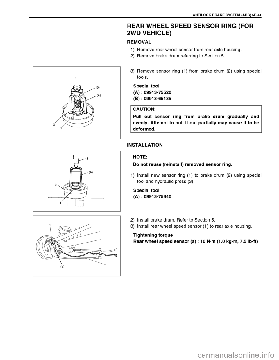
REAR WHEEL SPEED SENSOR RING (FOR
2WD VEHICLE)
REMOVAL
1) Remove rear wheel sensor from rear axle housing.
2) Remove brake drum referring to Section 5.
3) Remove sensor ring (1) from brake drum (2) using special
tools.
Special tool
(A) : 09913-75520
(B) : 09913-65135
INSTALLATION
1) Install new sensor ring (1) to brake drum (2) using special
tool and hydraulic press (3).
Special tool
(A) : 09913-75840
2) Install brake drum. Refer to Section 5.
3) Install rear wheel speed sensor (1) to rear axle housing.
Tightening torque
Rear wheel speed sensor (a) : 10 N·m (1.0 kg-m, 7.5 lb-ft) CAUTION:
Pull out sensor ring from brake drum gradually and
evenly. Attempt to pull it out partially may cause it to be
deformed.
NOTE:
Do not reuse (reinstall) removed sensor ring.
1
(a)
Page 367 of 698
5E-42 ANTILOCK BRAKE SYSTEM (ABS)
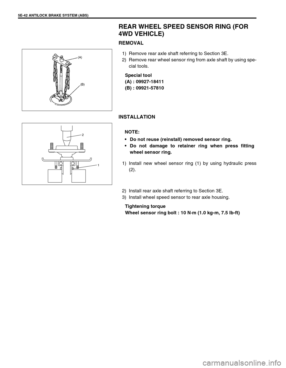
REAR WHEEL SPEED SENSOR RING (FOR
4WD VEHICLE)
REMOVAL
1) Remove rear axle shaft referring to Section 3E.
2) Remove rear wheel sensor ring from axle shaft by using spe-
cial tools.
Special tool
(A) : 09927-18411
(B) : 09921-57810
INSTALLATION
1) Install new wheel sensor ring (1) by using hydraulic press
(2).
2) Install rear axle shaft referring to Section 3E.
3) Install wheel speed sensor to rear axle housing.
Tightening torque
Wheel sensor ring bolt : 10 N·m (1.0 kg-m, 7.5 lb-ft)
NOTE:
Do not reuse (reinstall) removed sensor ring.
Do not damage to retainer ring when press fitting
wheel sensor ring.
1 2