lock SUZUKI SWIFT 2000 1.G RG413 Service Repair Manual
[x] Cancel search | Manufacturer: SUZUKI, Model Year: 2000, Model line: SWIFT, Model: SUZUKI SWIFT 2000 1.GPages: 698, PDF Size: 16.01 MB
Page 330 of 698
ANTILOCK BRAKE SYSTEM (ABS) 5E-5
ABS HYDRAULIC UNIT/CONTROL MODULE
ASSEMBLY
ABS control module is a component of ABS hydraulic unit/control
module assembly and has the following functions.
SELF-DIAGNOSIS FUNCTION
ABS control module diagnoses conditions of the system compo-
nent parts (whether or not there is any abnormality) all the time
and indicates the results (warning of abnormality occurrence and
DTC) through the ABS warning lamp as described below.
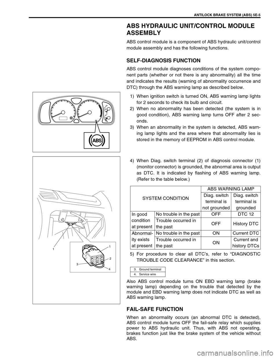
1) When ignition switch is turned ON, ABS warning lamp lights
for 2 seconds to check its bulb and circuit.
2) When no abnormality has been detected (the system is in
good condition), ABS warning lamp turns OFF after 2 sec-
onds.
3) When an abnormality in the system is detected, ABS warn-
ing lamp lights and the area where that abnormality lies is
stored in the memory of EEPROM in ABS control module.
4) When Diag. switch terminal (2) of diagnosis connector (1)
(monitor connector) is grounded, the abnormal area is output
as DTC. It is indicated by flashing of ABS warning lamp.
(Refer to the table below.)
5) For procedure to clear all DTC’s, refer to “DIAGNOSTIC
TROUBLE CODE CLEARANCE” in this section.
Also ABS control module turns ON EBD warning lamp (brake
warning lamp) depending on the trouble that detected by the
module and EBD warning lamp does not indicate DTC as well as
ABS warning lamp.
FAIL-SAFE FUNCTION
When an abnormality occurs (an abnormal DTC is detected),
ABS control module turns OFF the fail-safe relay which supplies
power to ABS hydraulic unit. Thus, with ABS not operating,
brakes function just like the brake system of the vehicle without
ABS.
SYSTEM CONDITIONABS WARNING LAMP
Diag. switch
terminal is
not groundedDiag. switch
terminal is
grounded
In good
condition
at presentNo trouble in the past OFF DTC 12
Trouble occurred in
the pastOFF History DTC
Abnormal-
ity exists
at presentNo trouble in the past ON Current DTC
Trouble occurred in
the pastONCurrent and
history DTCs
3. Ground terminal
4. Service wire
3 11
2
4
Page 331 of 698

5E-6 ANTILOCK BRAKE SYSTEM (ABS)
SYSTEM CIRCUIT
Page 332 of 698
ANTILOCK BRAKE SYSTEM (ABS) 5E-7
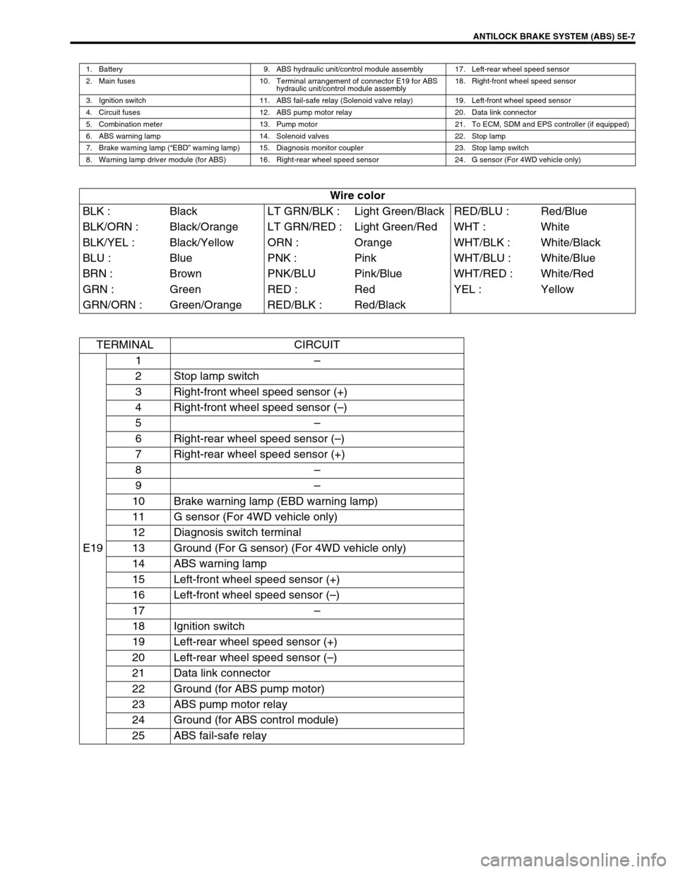
1. Battery 9. ABS hydraulic unit/control module assembly 17. Left-rear wheel speed sensor
2. Main fuses 10. Terminal arrangement of connector E19 for ABS
hydraulic unit/control module assembly18. Right-front wheel speed sensor
3. Ignition switch 11. ABS fail-safe relay (Solenoid valve relay) 19. Left-front wheel speed sensor
4. Circuit fuses 12. ABS pump motor relay 20. Data link connector
5. Combination meter 13. Pump motor 21. To ECM, SDM and EPS controller (if equipped)
6. ABS warning lamp 14. Solenoid valves 22. Stop lamp
7. Brake warning lamp (“EBD” warning lamp) 15. Diagnosis monitor coupler 23. Stop lamp switch
8. Warning lamp driver module (for ABS) 16. Right-rear wheel speed sensor 24. G sensor (For 4WD vehicle only)
Wire color
BLK : Black LT GRN/BLK : Light Green/Black RED/BLU : Red/Blue
BLK/ORN : Black/Orange LT GRN/RED : Light Green/Red WHT : White
BLK/YEL : Black/Yellow ORN : Orange WHT/BLK : White/Black
BLU : Blue PNK : Pink WHT/BLU : White/Blue
BRN : Brown PNK/BLU Pink/Blue WHT/RED : White/Red
GRN : Green RED : Red YEL : Yellow
GRN/ORN : Green/Orange RED/BLK : Red/Black
TERMINAL CIRCUIT
E191–
2 Stop lamp switch
3 Right-front wheel speed sensor (+)
4 Right-front wheel speed sensor (–)
5–
6 Right-rear wheel speed sensor (–)
7 Right-rear wheel speed sensor (+)
8–
9–
10 Brake warning lamp (EBD warning lamp)
11 G sensor (For 4WD vehicle only)
12 Diagnosis switch terminal
13 Ground (For G sensor) (For 4WD vehicle only)
14 ABS warning lamp
15 Left-front wheel speed sensor (+)
16 Left-front wheel speed sensor (–)
17–
18 Ignition switch
19 Left-rear wheel speed sensor (+)
20 Left-rear wheel speed sensor (–)
21 Data link connector
22 Ground (for ABS pump motor)
23 ABS pump motor relay
24 Ground (for ABS control module)
25 ABS fail-safe relay
Page 333 of 698
5E-8 ANTILOCK BRAKE SYSTEM (ABS)
DIAGNOSIS
To ensure that the trouble diagnosis is done accurately and
smoothly, observe “PRECAUTIONS IN DIAGNOSING TROU-
BLES” and follow “ABS DIAGNOSTIC FLOW TABLE”.
PRECAUTION IN DIAGNOSING TROUBLES
If the vehicles was operated in any of the following ways,
ABS warning lamp may light momentarily but this does not
indicate anything abnormal in ABS.
–The vehicle was driven with parking brake pulled.
–The vehicle was driven with brake dragging.
–The vehicle was stuck in mud, sand, etc.
–Wheel spin occurred while driving.
–Wheel(s) was rotated while the vehicle was jacked up.
Be sure to read “PRECAUTIONS FOR ELECTRONIC CIR-
CUIT SERVICE” in Section 0A before inspection and
observe what is written there.
Be sure to use the trouble diagnosis procedure as described
in the flow table. Failure to follow the flow table may result in
incorrect diagnosis. (Some other diagnosis trouble code may
be stored by mistake in the memory of ABS control module
during inspection.)
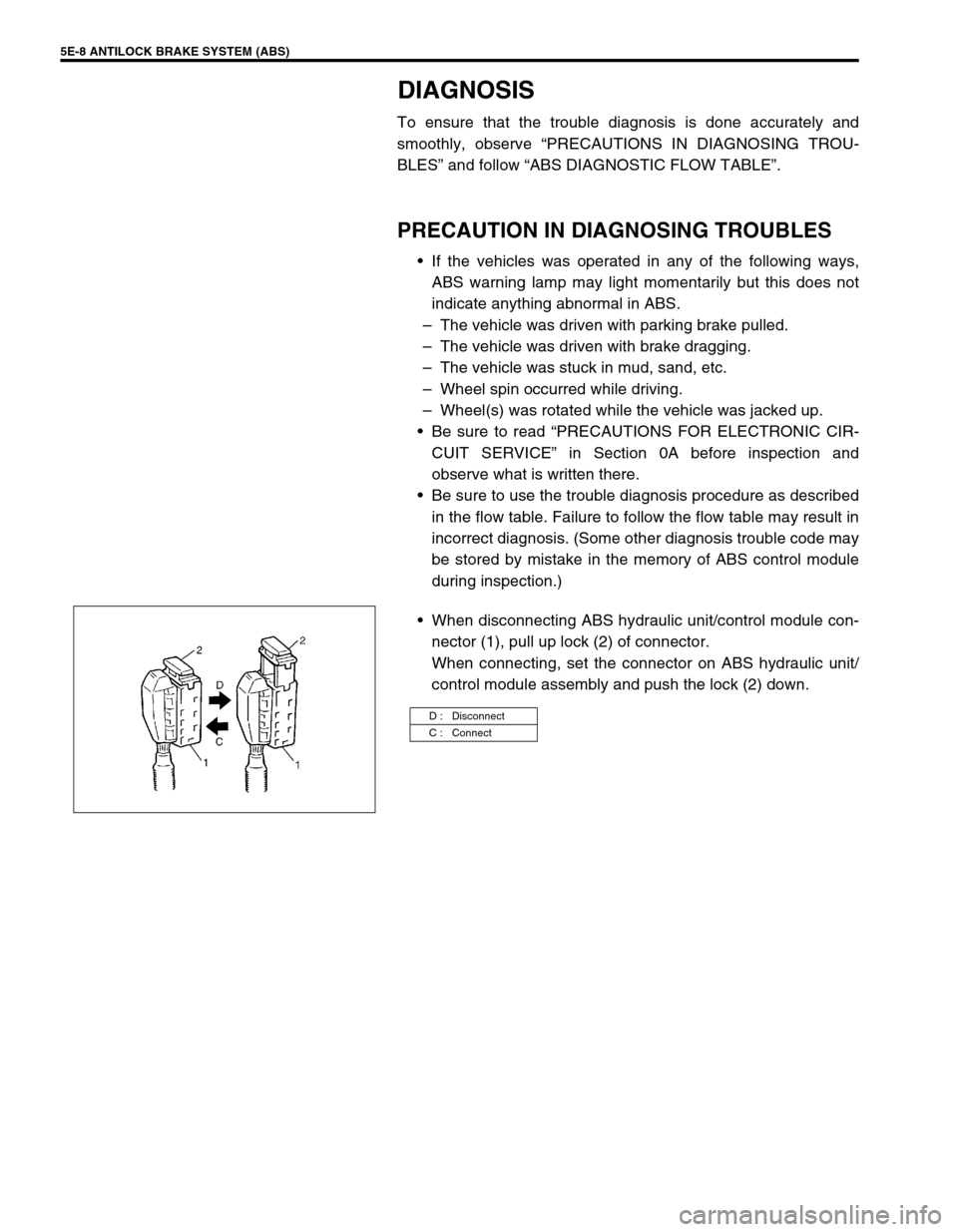
When disconnecting ABS hydraulic unit/control module con-
nector (1), pull up lock (2) of connector.
When connecting, set the connector on ABS hydraulic unit/
control module assembly and push the lock (2) down.
D : Disconnect
C : Connect
Page 334 of 698
ANTILOCK BRAKE SYSTEM (ABS) 5E-9
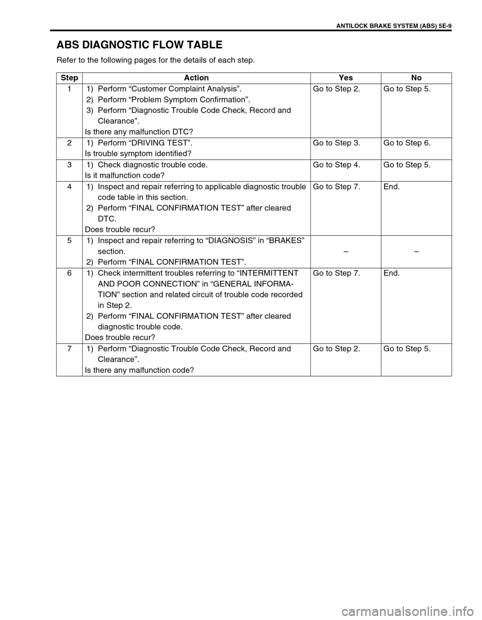
ABS DIAGNOSTIC FLOW TABLE
Refer to the following pages for the details of each step.
Step Action Yes No
11)Perform “Customer Complaint Analysis”.
2) Perform “Problem Symptom Confirmation”.
3) Perform “Diagnostic Trouble Code Check, Record and
Clearance”.
Is there any malfunction DTC?Go to Step 2. Go to Step 5.
21)Perform “DRIVING TEST”.
Is trouble symptom identified?Go to Step 3. Go to Step 6.
3 1) Check diagnostic trouble code.
Is it malfunction code?Go to Step 4. Go to Step 5.
4 1) Inspect and repair referring to applicable diagnostic trouble
code table in this section.
2) Perform “FINAL CONFIRMATION TEST” after cleared
DTC.
Does trouble recur?Go to Step 7. End.
5 1) Inspect and repair referring to “DIAGNOSIS” in “BRAKES”
section.
2) Perform “FINAL CONFIRMATION TEST”.––
6 1) Check intermittent troubles referring to “INTERMITTENT
AND POOR CONNECTION” in “GENERAL INFORMA-
TION” section and related circuit of trouble code recorded
in Step 2.
2) Perform “FINAL CONFIRMATION TEST” after cleared
diagnostic trouble code.
Does trouble recur?Go to Step 7. End.
71)Perform “Diagnostic Trouble Code Check, Record and
Clearance”.
Is there any malfunction code?Go to Step 2. Go to Step 5.
Page 335 of 698

5E-10 ANTILOCK BRAKE SYSTEM (ABS)
1) MALFUNCTION ANALYSIS
a) Customer Complaint Analysis
Record details of the problem (failure, complaint) and how it occurred as described by the customer.
For this purpose, use of such a questionnaire form as shown below will facilitate collecting information to
the point required for proper analysis and diagnosis.
CUSTOMER QUESTIONNAIRE (EXAMPLE)
b) Problem Symptom Confirmation
Check if what the customer claimed in “CUSTOMER QUESTIONNAIRE” is actually found in the vehicle
and if that symptom is found, whether it is identified as a failure. (This step should be shared with the cus-
tomer if possible.) Check warning lamps related to brake system referring to “EBD WARNING LAMP
(BRAKE WARNING LAMP) CHECK” and “ABS WARNING LAMP CHECK” in this section.
Page 336 of 698
ANTILOCK BRAKE SYSTEM (ABS) 5E-11
c) Diagnostic Trouble Code (DTC) Check, Record and Clearance
Perform “DIAGNOSTIC TROUBLE CODE CHECK” procedure in this section, record it and then clear it
referring to “DIAGNOSTIC TROUBLE CODE CLEARANCE” in this section.
If the malfunction DTC which was once displayed and then cleared cannot be detected (indicated) again
when the ignition switch is turned ON, attempt to diagnose the trouble based on the DTC recorded in this
step may mislead the diagnosis or make diagnosing difficult. Proceed to Step 2) to check control module
for proper self-diagnosis function.
If the malfunction DTC which was once displayed and then cleared can be detected (indicated) again when
ignition switch is turned ON, proceed to Step 3).
2) DRIVING TEST
Test drive the vehicle at 40 km/h for more than a minute and check if any trouble symptom (such as abnor-
mal lighting of ABS warning light) exists.
If the malfunction DTC is confirmed again at ignition switch ON, driving test as described in above is not nec-
essary. Proceed to Step 3).
3) DIAGNOSTIC TROUBLE CODE CHECK
Recheck diagnostic trouble code referring to “DTC CHECK” as shown in the following page.
4) DIAGNOSTIC TROUBLE CODE FLOW TABLE
According to Diagnostic flow table for the diagnostic trouble code confirmation in Step 3), locate the cause of
the trouble, namely in a sensor, switch, wire harness, connector, actuator assembly or other part and repair
or replace faulty parts.
5)“DIAGNOSIS” IN “BRAKES” SECTION
Check the parts or system suspected as a possible cause referring to “DIAGNOSIS” in “BRAKES” section
and based on symptoms appearing on the vehicle (symptom obtained through Steps 1)-a, 1)-b and 2) and
repair or replace faulty parts, if any).
6) CHECK FOR INTERMITTENT PROBLEM
Check parts where an intermittent trouble is easy to occur (e.g., wire harness, connector, etc.), referring to
“INTERMITTENT TROUBLE” in “GENERAL INFORMATION” section and related circuit of trouble code
recorded in Step 1)-c.
7) FINAL CONFIRMATION TEST
Confirm that the problem symptom has gone and the ABS is free from any abnormal conditions. If what has
been repaired is related to the malfunction DTC, clear the DTC once and perform test driving and confirm
that no DTC is indicated.
Page 337 of 698
5E-12 ANTILOCK BRAKE SYSTEM (ABS)
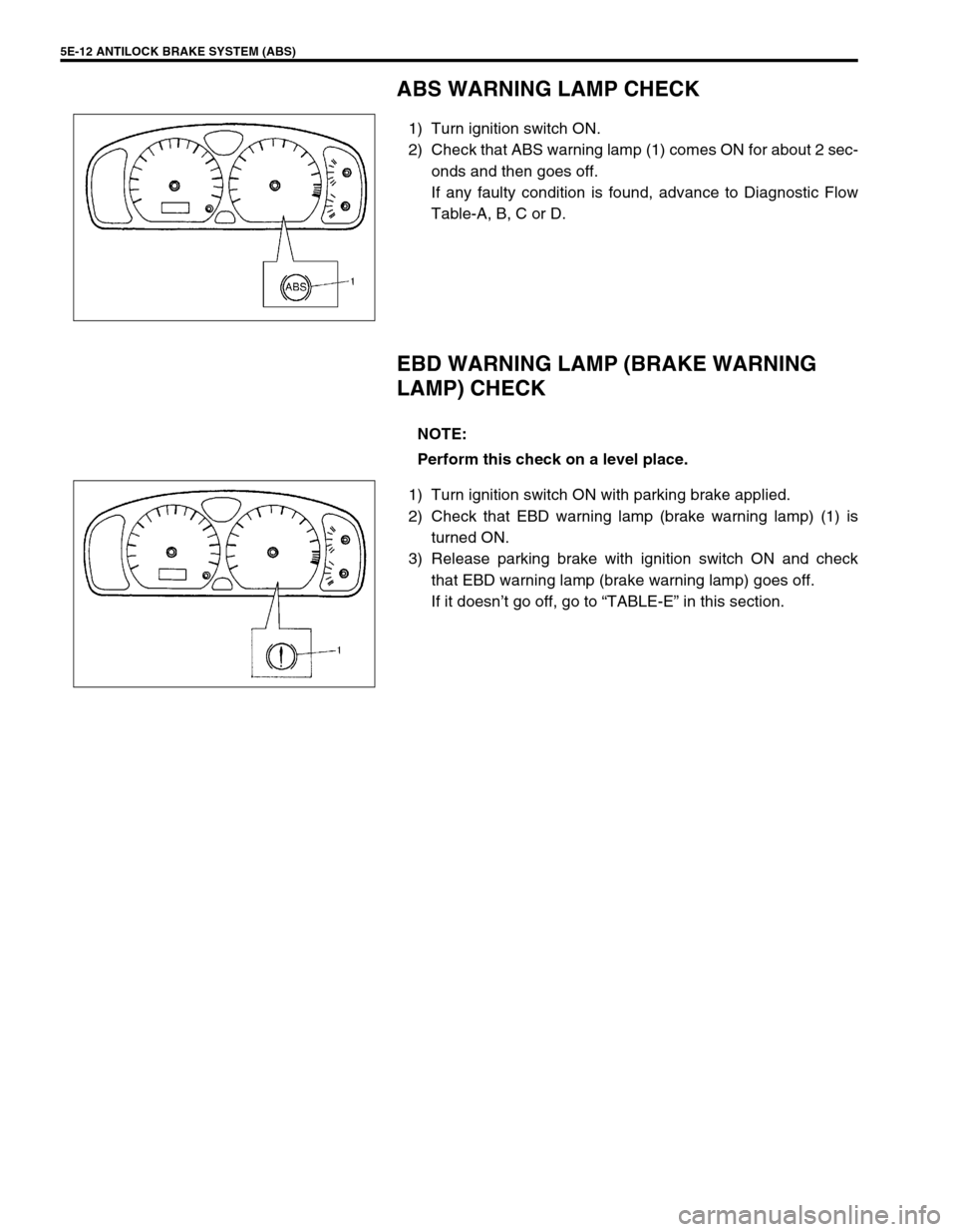
ABS WARNING LAMP CHECK
1) Turn ignition switch ON.
2) Check that ABS warning lamp (1) comes ON for about 2 sec-
onds and then goes off.
If any faulty condition is found, advance to Diagnostic Flow
Table-A, B, C or D.
EBD WARNING LAMP (BRAKE WARNING
LAMP) CHECK
1) Turn ignition switch ON with parking brake applied.
2) Check that EBD warning lamp (brake warning lamp) (1) is
turned ON.
3) Release parking brake with ignition switch ON and check
that EBD warning lamp (brake warning lamp) goes off.
If it doesn’t go off, go to “TABLE-E” in this section.
NOTE:
Perform this check on a level place.
Page 338 of 698
ANTILOCK BRAKE SYSTEM (ABS) 5E-13
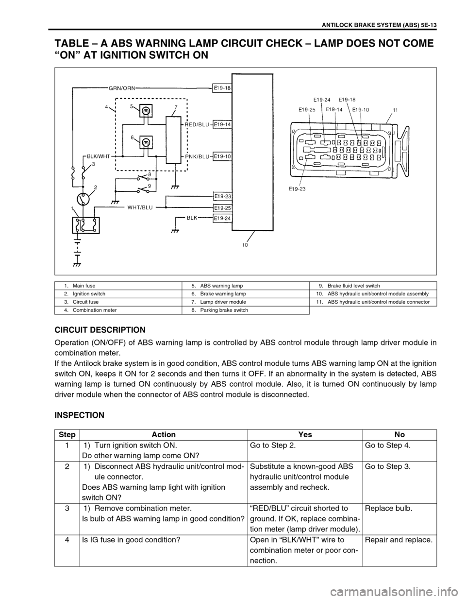
TABLE – A ABS WARNING LAMP CIRCUIT CHECK – LAMP DOES NOT COME
“ON” AT IGNITION SWITCH ON
CIRCUIT DESCRIPTION
Operation (ON/OFF) of ABS warning lamp is controlled by ABS control module through lamp driver module in
combination meter.
If the Antilock brake system is in good condition, ABS control module turns ABS warning lamp ON at the ignition
switch ON, keeps it ON for 2 seconds and then turns it OFF. If an abnormality in the system is detected, ABS
warning lamp is turned ON continuously by ABS control module. Also, it is turned ON continuously by lamp
driver module when the connector of ABS control module is disconnected.
INSPECTION
1. Main fuse 5. ABS warning lamp 9. Brake fluid level switch
2. Ignition switch 6. Brake warning lamp 10. ABS hydraulic unit/control module assembly
3. Circuit fuse 7. Lamp driver module 11. ABS hydraulic unit/control module connector
4. Combination meter 8. Parking brake switch
Step Action Yes No
1 1) Turn ignition switch ON.
Do other warning lamp come ON?Go to Step 2. Go to Step 4.
2 1) Disconnect ABS hydraulic unit/control mod-
ule connector.
Does ABS warning lamp light with ignition
switch ON?Substitute a known-good ABS
hydraulic unit/control module
assembly and recheck.Go to Step 3.
3 1) Remove combination meter.
Is bulb of ABS warning lamp in good condition?“RED/BLU” circuit shorted to
ground. If OK, replace combina-
tion meter (lamp driver module).Replace bulb.
4 Is IG fuse in good condition? Open in “BLK/WHT” wire to
combination meter or poor con-
nection.Repair and replace.
Page 339 of 698
5E-14 ANTILOCK BRAKE SYSTEM (ABS)
TABLE – B ABS WARNING LAMP CIRCUIT CHECK – LAMP COMES “ON”
STEADY
Refer to TABLE – A for System Circuit Diagram and Circuit Description.
INSPECTION
Step Action Yes No
1 Perform diagnostic trouble code check. Is there
any DTC (including code No.12, NO CODES on
SUZUKI scan tool) exists?Go to Step 2. Go to Step 3.
2 Does malfunction DTC (other than code No.12)
exist at Step 1?Go to Step 7 of “ABS
DIAGNOSTIC FLOW
TABLE” in this section.Go to Step 3.
3 1) Disconnect ABS hydraulic unit/control mod-
ule connector.
2) Check for proper connection to ABS
hydraulic unit/control module connector at
terminals “E19-14”, “E19-18” and “E19-24”.
3) If OK then ignition switch ON and measure
voltage at terminal “E19-18” of connector.
Is it 10 – 14 V?Go to Step 4.“GRN/ORN” circuit open.
4 1) With ABS hydraulic unit/control module con-
nector disconnected, turn ignition switch ON
and light ABS warning lamp.
2) Connect terminal “E19-14” of disconnected
connector to ground using service wire.
Does ABS warning lamp turn off?Go to Step 5.“RED/BLU” circuit open.
If wire and connection are
OK, replace combination
meter (lamp driver mod-
ule).
5 1) Measure resistance from connector terminal
“E19-24” to body ground.
Is continuity indicated?Substitute a known-good
ABS hydraulic unit/con-
trol module assembly and
recheck.“BLK” circuit open.