lock SUZUKI SWIFT 2000 1.G RG413 Service Owner's Guide
[x] Cancel search | Manufacturer: SUZUKI, Model Year: 2000, Model line: SWIFT, Model: SUZUKI SWIFT 2000 1.GPages: 698, PDF Size: 16.01 MB
Page 133 of 698
3B-12 MANUAL RACK AND PINION
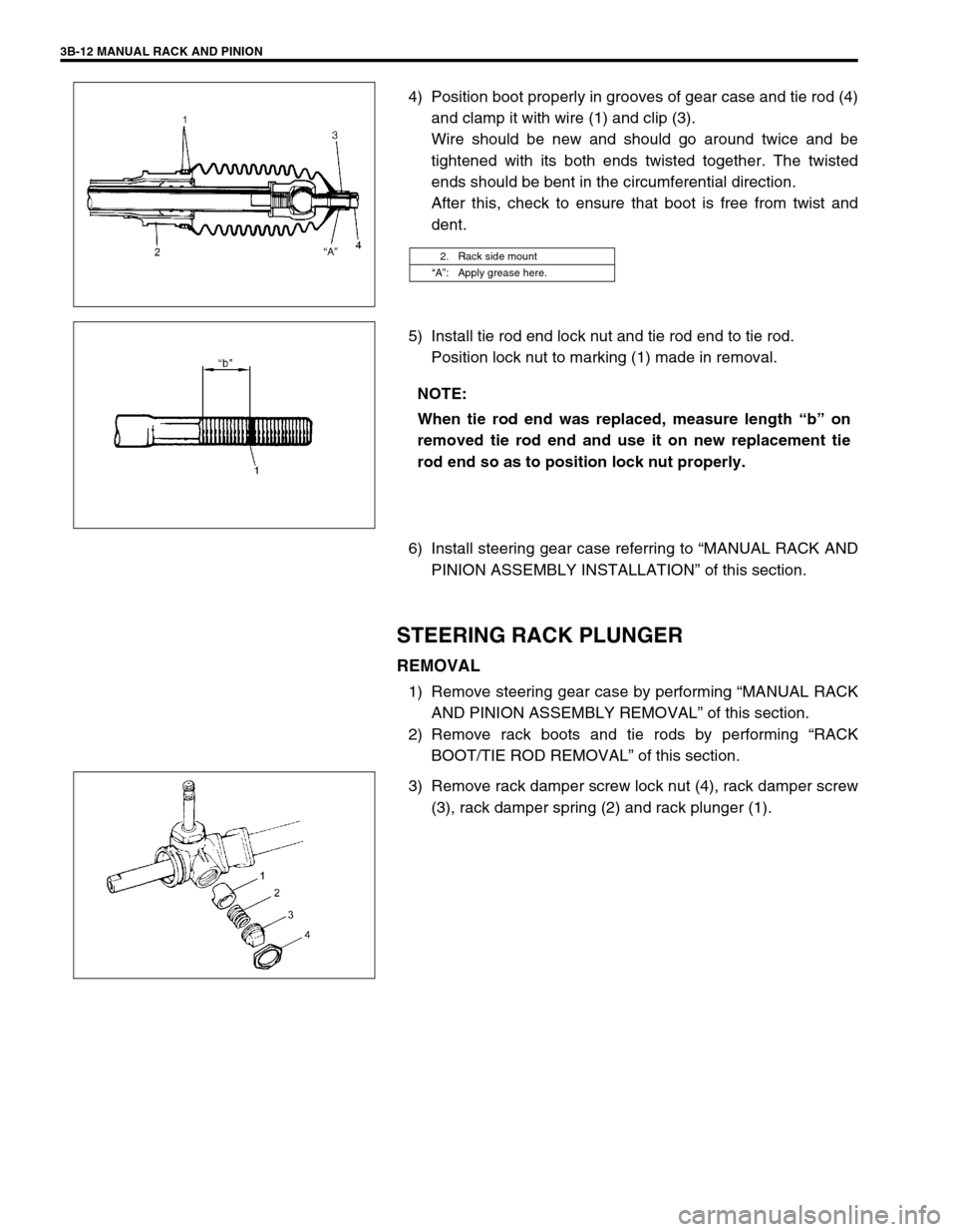
4) Position boot properly in grooves of gear case and tie rod (4)
and clamp it with wire (1) and clip (3).
Wire should be new and should go around twice and be
tightened with its both ends twisted together. The twisted
ends should be bent in the circumferential direction.
After this, check to ensure that boot is free from twist and
dent.
5) Install tie rod end lock nut and tie rod end to tie rod.
Position lock nut to marking (1) made in removal.
6) Install steering gear case referring to “MANUAL RACK AND
PINION ASSEMBLY INSTALLATION” of this section.
STEERING RACK PLUNGER
REMOVAL
1) Remove steering gear case by performing “MANUAL RACK
AND PINION ASSEMBLY REMOVAL” of this section.
2) Remove rack boots and tie rods by performing “RACK
BOOT/TIE ROD REMOVAL” of this section.
3) Remove rack damper screw lock nut (4), rack damper screw
(3), rack damper spring (2) and rack plunger (1).
2. Rack side mount
“A”: Apply grease here.
NOTE:
When tie rod end was replaced, measure length “b” on
removed tie rod end and use it on new replacement tie
rod end so as to position lock nut properly.
Page 134 of 698
MANUAL RACK AND PINION 3B-13
INSPECTION
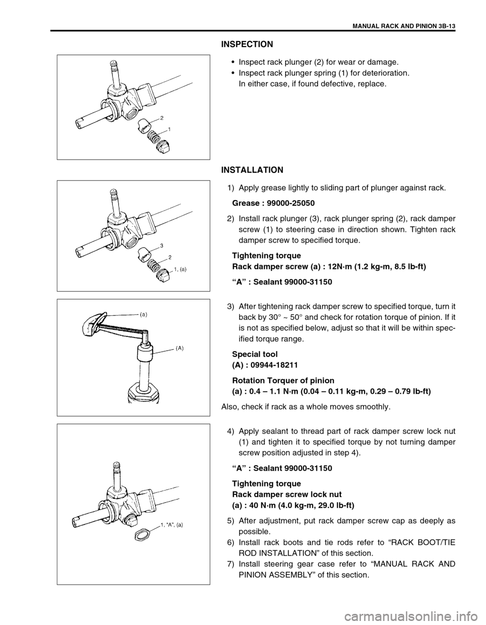
Inspect rack plunger (2) for wear or damage.
Inspect rack plunger spring (1) for deterioration.
In either case, if found defective, replace.
INSTALLATION
1) Apply grease lightly to sliding part of plunger against rack.
Grease : 99000-25050
2) Install rack plunger (3), rack plunger spring (2), rack damper
screw (1) to steering case in direction shown. Tighten rack
damper screw to specified torque.
Tightening torque
Rack damper screw (a) : 12N·m (1.2 kg-m, 8.5 lb-ft)
“A” : Sealant 99000-31150
3) After tightening rack damper screw to specified torque, turn it
back by 30° ~ 50° and check for rotation torque of pinion. If it
is not as specified below, adjust so that it will be within spec-
ified torque range.
Special tool
(A) : 09944-18211
Rotation Torquer of pinion
(a) : 0.4 – 1.1 N·m (0.04 – 0.11 kg-m, 0.29 – 0.79 lb-ft)
Also, check if rack as a whole moves smoothly.
4) Apply sealant to thread part of rack damper screw lock nut
(1) and tighten it to specified torque by not turning damper
screw position adjusted in step 4).
“A” : Sealant 99000-31150
Tightening torque
Rack damper screw lock nut
(a) : 40 N·m (4.0 kg-m, 29.0 lb-ft)
5) After adjustment, put rack damper screw cap as deeply as
possible.
6) Install rack boots and tie rods refer to “RACK BOOT/TIE
ROD INSTALLATION” of this section.
7) Install steering gear case refer to “MANUAL RACK AND
PINION ASSEMBLY” of this section.
Page 137 of 698
3B-16 MANUAL RACK AND PINION
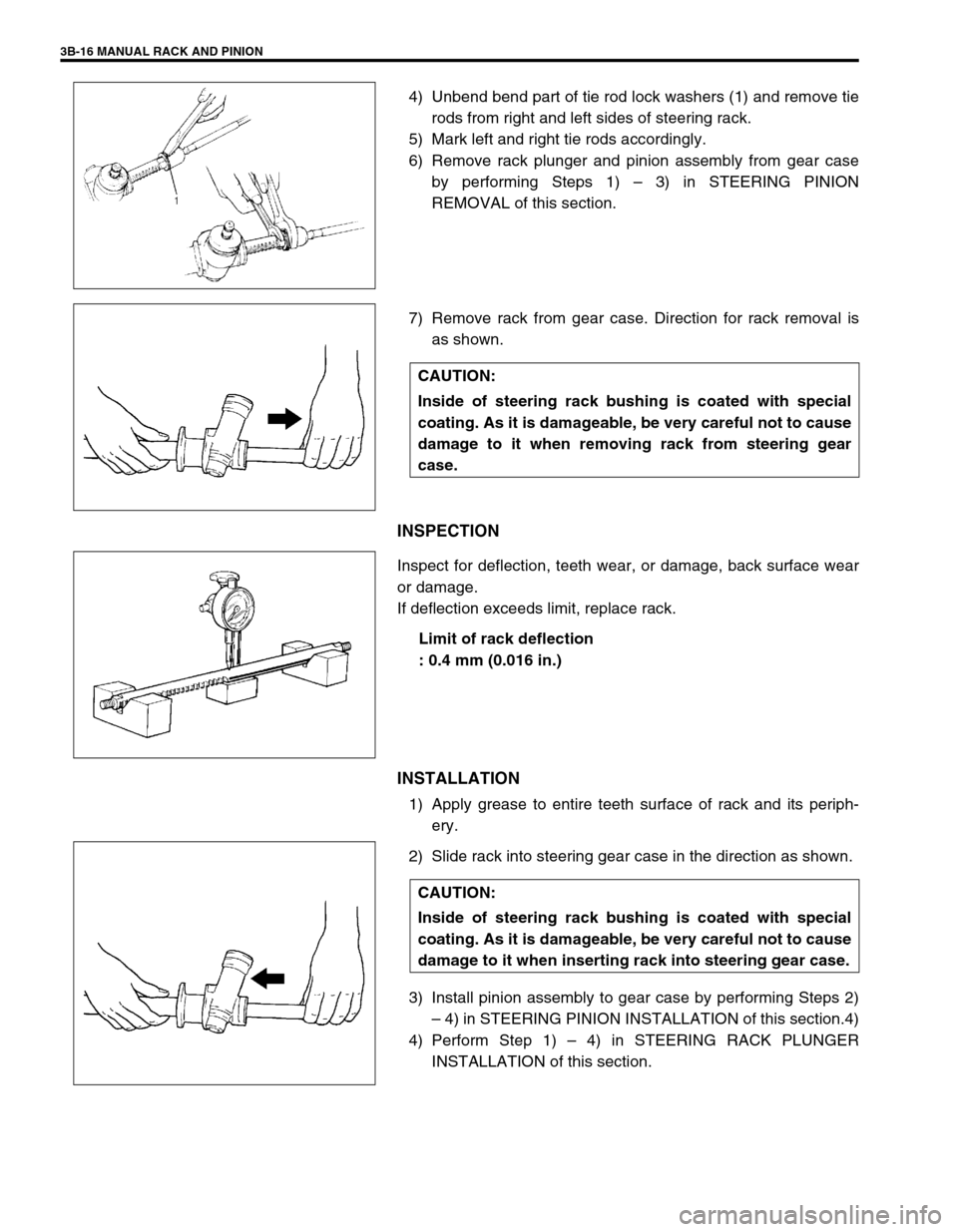
4) Unbend bend part of tie rod lock washers (1) and remove tie
rods from right and left sides of steering rack.
5) Mark left and right tie rods accordingly.
6) Remove rack plunger and pinion assembly from gear case
by performing Steps 1) – 3) in STEERING PINION
REMOVAL of this section.
7) Remove rack from gear case. Direction for rack removal is
as shown.
INSPECTION
Inspect for deflection, teeth wear, or damage, back surface wear
or damage.
If deflection exceeds limit, replace rack.
Limit of rack deflection
: 0.4 mm (0.016 in.)
INSTALLATION
1) Apply grease to entire teeth surface of rack and its periph-
ery.
2) Slide rack into steering gear case in the direction as shown.
3) Install pinion assembly to gear case by performing Steps 2)
– 4) in STEERING PINION INSTALLATION of this section.4)
4) Perform Step 1) – 4) in STEERING RACK PLUNGER
INSTALLATION of this section.
CAUTION:
Inside of steering rack bushing is coated with special
coating. As it is damageable, be very careful not to cause
damage to it when removing rack from steering gear
case.
CAUTION:
Inside of steering rack bushing is coated with special
coating. As it is damageable, be very careful not to cause
damage to it when inserting rack into steering gear case.
Page 142 of 698
ELECTRICAL POWER STEERING (P/S) SYSTEM 3B1-1
6F1
6F2
6G
6H
6K
7A
7A1
3B1
7D
7E
7F
8A
8B
8C
8D
8E
9
10
10A
10B
SECTION 3B1
ELECTRICAL POWER STEERING (P/S) SYSTEM
CONTENTS
GENERAL DESCRIPTION .............................3B1-2
SYSTEM COMPONENTS ........................... 3B1-2
WIRING DIAGRAM ..................................... 3B1-3
DIAGNOSIS ....................................................3B1-4
ON-BOARD DIAGNOSTIC SYSTEM .......... 3B1-4
PRECAUTIONS IN DIAGNOSING
TROUBLES ................................................. 3B1-4
SYSTEM CHECK FLOW TABLE ................ 3B1-5
MALFUNCTION INDICATOR LAMP
(“EPS” WARNING LAMP) CHECK.............. 3B1-7
DTC CHECK ............................................... 3B1-8
DTC CLEARANCE ...................................... 3B1-9
SERIAL DATA LINK CIRCUIT CHECK ..... 3B1-10
DTC TABLE .............................................. 3B1-11
TABLE A - MALFUNCTION INDICATOR
LAMP DOES NOT COME ON AT
IGNITION SWITCH ON BUT LEAVING
ENGINE OFF ............................................ 3B1-13
TABLE B - MALFUNCTION INDICATOR
LAMP FLASHES AT IGNITION SWITCH
ON ............................................................. 3B1-15
TABLE C - MALFUNCTION INDICATOR
LAMP DOES NOT FLASH, JUST
REMAINS ON OR JUST REMAINS OFF
EVEN WITH DIAGNOSIS SWITCH
TERMINAL GROUNDED .......................... 3B1-15
DTC C1111 (DTC No.11) TORQUE
SENSOR MAIN CIRCUIT FAILURE ......... 3B1-16
DTC C1113 (DTC No.13) TORQUE
SENSOR MAIN AND SUB CIRCUIT
FAILURE ................................................... 3B1-16DTC C1115 (DTC No.15) TORQUE
SENSOR SUB CIRCUIT FAILURE........... 3B1-16
DTC C1114 (DTC No.14) TORQUE
SENSOR 5V POWER SUPPLY CIRCUIT
FAILURE ................................................... 3B1-17
DTC C1116 (DTC No.16) TORQUE
SENSOR 8V POWER SUPPLY CIRCUIT
FAILURE ................................................... 3B1-18
DTC C1121/C1123/C1124
(DTC No.21/23/24) VSS CIRCUIT
FAILURE ................................................... 3B1-19
DTC C1122 (DTC No.22) ENGINE
SPEED SIGNAL CIRCUIT FAILURE ........ 3B1-20
DTC C1141/C1142/C1143/C1144/C1145
(DTC No.41/42/43/44/45) MOTOR
CIRCUIT FAILURE ................................... 3B1-21
DTC C1151 (DTC No.51) CLUTCH
CIRCUIT FAILURE ................................... 3B1-22
DTC C1153(DTC No.53) P/S CONTROL
MODULE POWER SUPPLY CIRCUIT
FAILURE ................................................... 3B1-24
DTC C1152/C1154/C1155
(DTC No.52/54/55) P/S CONTROL
MODULE FAILURE .................................. 3B1-24
TROUBLE DIAGNOSIS (FOR TROUBLE
NOT INDICATED BY ON BOARD
DIAGNOSTIC SYSTEM)........................... 3B1-25
INSPECTION OF P/S CONTROL
MODULE AND ITS CIRCUITS ................. 3B1-26
STEERING WHEEL PLAY
INSPECTION ............................................ 3B1-28 WARNING:
For vehicles equipped with Supplemental Restraint (Air Bag) System :
Service on and around the air bag system components or wiring must be performed only by an
authorized SUZUKI dealer. Refer to “Air Bag System Components and Wiring Location View” under
“General Description” in air bag system section in order to confirm whether you are performing ser-
vice on or near the air bag system components or wiring. Please observe all WARNINGS and “Ser-
vice Precautions” under “On-Vehicle Service” in air bag system section before performing service
on or around the air bag system components or wiring. Failure to follow WARNINGS could result in
unintentional activation of the system or could render the system inoperative. Either of these two
conditions may result in severe injury.
Technical service work must be started at least 90 seconds after the ignition switch is turned to the
“LOCK” position and the negative cable is disconnected from the battery. Otherwise, the system
may be activated by reserve energy in the Sensing and Diagnostic Module (SDM).
Page 160 of 698
ELECTRICAL POWER STEERING (P/S) SYSTEM 3B1-19
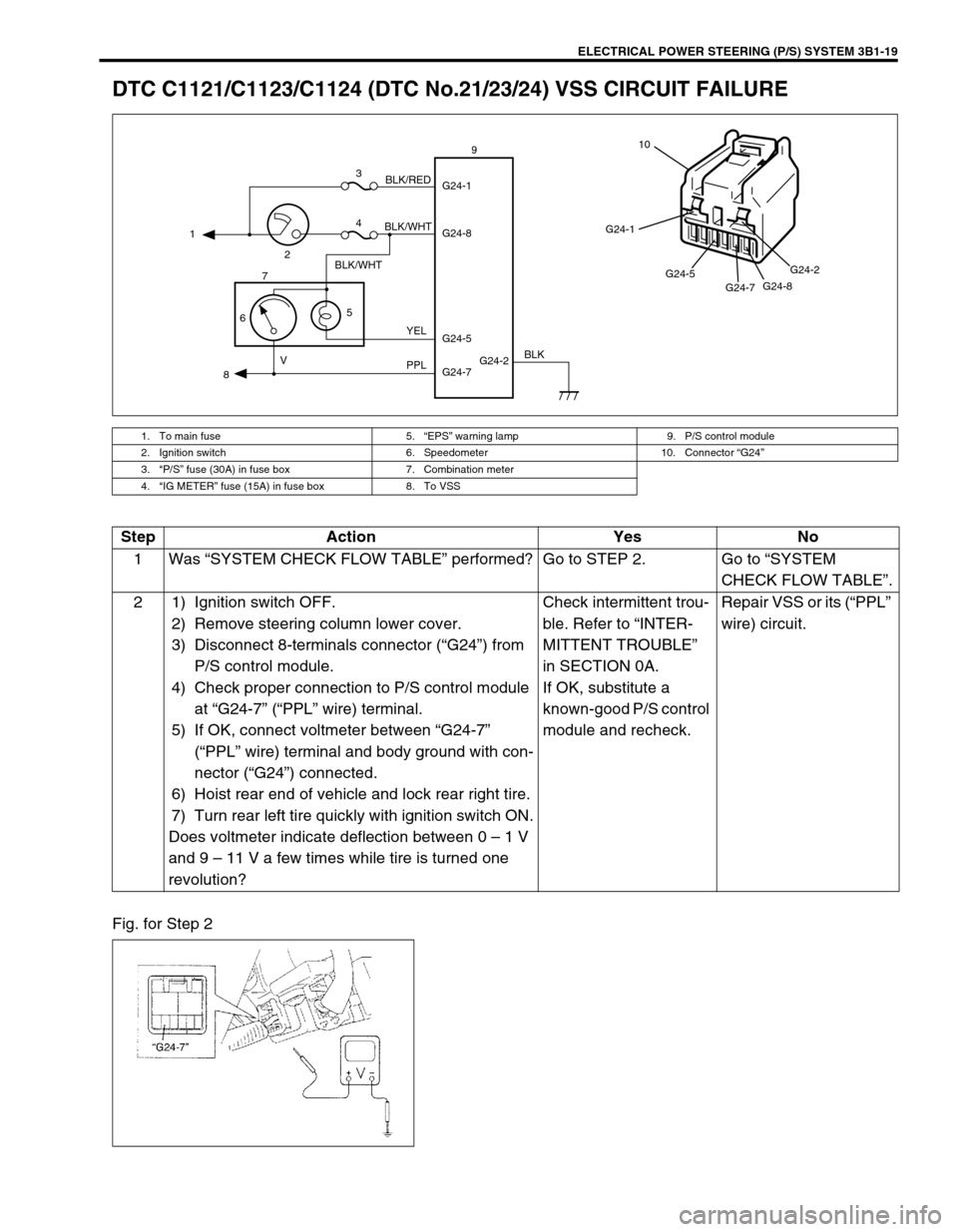
DTC C1121/C1123/C1124 (DTC No.21/23/24) VSS CIRCUIT FAILURE
Fig. for Step 2
1. To main fuse 5.“EPS” warning lamp 9. P/S control module
2. Ignition switch 6. Speedometer 10. Connector “G24”
3.“P/S” fuse (30A) in fuse box 7. Combination meter
4.“IG METER” fuse (15A) in fuse box 8. To VSS
G24-2 G24-1
G24-8
G24-7 G24-5 1
23
4
5
67
89
BLK/WHT
BLK/WHTBLK/RED
YEL
PPL VBLK
G24-1
G24-5
G24-7G24-8G24-2
10
Step Action Yes No
1Was “SYSTEM CHECK FLOW TABLE” performed? Go to STEP 2. Go to “SYSTEM
CHECK FLOW TABLE”.
2 1) Ignition switch OFF.
2) Remove steering column lower cover.
3) Disconnect 8-terminals connector (“G24”) from
P/S control module.
4) Check proper connection to P/S control module
at “G24-7” (“PPL” wire) terminal.
5) If OK, connect voltmeter between “G24-7”
(“PPL” wire) terminal and body ground with con-
nector (“G24”) connected.
6) Hoist rear end of vehicle and lock rear right tire.
7) Turn rear left tire quickly with ignition switch ON.
Does voltmeter indicate deflection between 0 – 1 V
and 9 – 11 V a few times while tire is turned one
revolution?Check intermittent trou-
ble. Refer to “INTER-
MITTENT TROUBLE”
in SECTION 0A.
If OK, substitute a
known-good P/S control
module and recheck.Repair VSS or its (“PPL”
wire) circuit.
Page 168 of 698
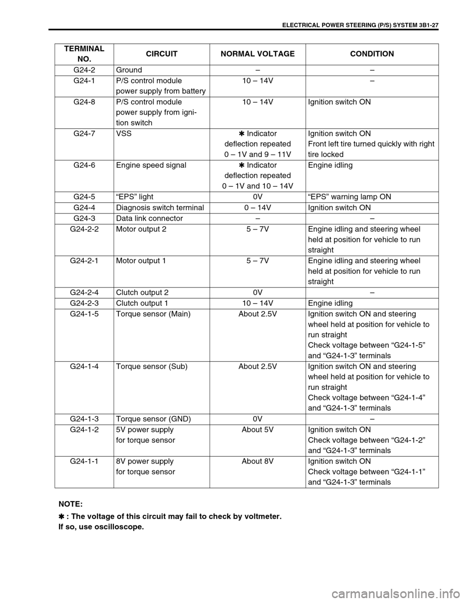
ELECTRICAL POWER STEERING (P/S) SYSTEM 3B1-27
TERMINAL
NO.CIRCUIT NORMAL VOLTAGE CONDITION
G24-2 Ground––
G24-1 P/S control module
power supply from battery10 – 14V–
G24-8 P/S control module
power supply from igni-
tion switch10 – 14V Ignition switch ON
G24-7 VSS✱ Indicator
deflection repeated
0 – 1V and 9 – 11VIgnition switch ON
Front left tire turned quickly with right
tire locked
G24-6 Engine speed signal✱ Indicator
deflection repeated
0 – 1V and 10 – 14VEngine idling
G24-5“EPS” light 0V“EPS” warning lamp ON
G24-4 Diagnosis switch terminal 0 – 14V Ignition switch ON
G24-3 Data link connector––
G24-2-2 Motor output 2 5 – 7V Engine idling and steering wheel
held at position for vehicle to run
straight
G24-2-1 Motor output 1 5 – 7V Engine idling and steering wheel
held at position for vehicle to run
straight
G24-2-4 Clutch output 2 0V–
G24-2-3 Clutch output 1 10 – 14V Engine idling
G24-1-5 Torque sensor (Main) About 2.5V Ignition switch ON and steering
wheel held at position for vehicle to
run straight
Check voltage between “G24-1-5”
and “G24-1-3” terminals
G24-1-4 Torque sensor (Sub) About 2.5V Ignition switch ON and steering
wheel held at position for vehicle to
run straight
Check voltage between “G24-1-4”
and “G24-1-3” terminals
G24-1-3 Torque sensor (GND) 0V–
G24-1-2 5V power supply
for torque sensorAbout 5V Ignition switch ON
Check voltage between “G24-1-2”
and “G24-1-3” terminals
G24-1-1 8V power supply
for torque sensorAbout 8V Ignition switch ON
Check voltage between “G24-1-1”
and “G24-1-3” terminals
NOTE:
✱
✱✱ ✱ : The voltage of this circuit may fail to check by voltmeter.
If so, use oscilloscope.
Page 174 of 698
STEERING WHEEL AND COLUMN 3C-1
6F1
6F2
6G
6H
6K
7A
7A1
7B1
3C1
7E
7F
8A
8B
8C
8D
8E
9
10
10A
10B
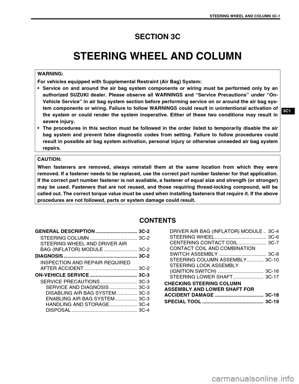
SECTION 3C
STEERING WHEEL AND COLUMN
CONTENTS
GENERAL DESCRIPTION .............................. 3C-2
STEERING COLUMN .................................. 3C-2
STEERING WHEEL AND DRIVER AIR
BAG (INFLATOR) MODULE ........................ 3C-2
DIAGNOSIS ..................................................... 3C-2
INSPECTION AND REPAIR REQUIRED
AFTER ACCIDENT ...................................... 3C-2
ON-VEHICLE SERVICE .................................. 3C-3
SERVICE PRECAUTIONS........................... 3C-3
SERVICE AND DIAGNOSIS .................... 3C-3
DISABLING AIR BAG SYSTEM ............... 3C-3
ENABLING AIR BAG SYSTEM ................ 3C-3
HANDLING AND STORAGE.................... 3C-4
DISPOSAL ............................................... 3C-4DRIVER AIR BAG (INFLATOR) MODULE .. 3C-4
STEERING WHEEL ..................................... 3C-6
CENTERING CONTACT COIL .................... 3C-7
CONTACT COIL AND COMBINATION
SWITCH ASSEMBLY .................................. 3C-8
STEERING COLUMN ASSEMBLY............ 3C-10
STEERING LOCK ASSEMBLY
(IGNITION SWITCH) ................................. 3C-16
STEERING LOWER SHAFT...................... 3C-17
CHECKING STEERING COLUMN
ASSEMBLY AND LOWER SHAFT FOR
ACCIDENT DAMAGE ................................... 3C-18
SPECIAL TOOL ............................................ 3C-19
WARNING:
For vehicles equipped with Supplemental Restraint (Air Bag) System:
Service on and around the air bag system components or wiring must be performed only by an
authorized SUZUKI dealer. Please observe all WARNINGS and “Service Precautions” under “On-
Vehicle Service” in air bag system section before performing service on or around the air bag sys-
tem components or wiring. Failure to follow WARNINGS could result in unintentional activation of
the system or could render the system inoperative. Either of these two conditions may result in
severe injury.
The procedures in this section must be followed in the order listed to temporarily disable the air
bag system and prevent false diagnostic codes from setting. Failure to follow procedures could
result in possible air bag system activation, personal injury or otherwise unneeded air bag system
repairs.
CAUTION:
When fasteners are removed, always reinstall them at the same location from which they were
removed. If a fastener needs to be replaced, use the correct part number fastener for that application.
If the correct part number fastener is not available, a fastener of equal size and strength (or stronger)
may be used. Fasteners that are not reused, and those requiring thread-locking compound, will be
called out. The correct torque value must be used when installing fasteners that require it. If the above
procedures are not followed, parts or system damage could result.
Page 175 of 698
3C-2 STEERING WHEEL AND COLUMN
GENERAL DESCRIPTION
STEERING COLUMN
This double tube type steering column has following three important features in addition to the steering function
:
The column is energy absorbing, designed to compress in a front-end collision.
The ignition switch and lock are mounted conveniently on this column.
With the column mounted lock, the ignition and steering operations can be locked to inhibit theft of the vehi-
cle.
To insure the energy absorbing action, it is important that only the specified screws, bolts, and nuts be used as
designated and that they are tightened to the specified torque.
When the column assembly is removed from the vehicle, special care must be taken in handling it. Use of a
steering wheel puller other than the one recommended in this manual or a sharp blow on the end of the steering
shaft, leaning on the assembly, or dropping the assembly could shear the plastic shear pins which maintain col-
umn length and position.
STEERING WHEEL AND DRIVER AIR BAG (INFLATOR) MODULE
The driver air bag (inflator) module is one of the supplemental restraint (air bag) system components and is
mounted to the center of the steering wheel. During certain frontal crashes, the air bag system supplements the
restraint of the driver’s and passenger’s seat belts by deploying the air bags.
The air bag (inflator) module should be handled with care to prevent accidental deployment. When servicing, be
sure to observe all WARNINGS and CAUTIONS and “SERVICE PRECAUTIONS” under “ON-VEHICLE SER-
VICE” in Section 10B.
DIAGNOSIS
For maintenance service of the steering wheel and column, refer to Section 0B.
For diagnosis of the steering wheel and column, refer to Section 3.
For diagnosis of the air bag system, refer to Section 10B.
INSPECTION AND REPAIR REQUIRED AFTER ACCIDENT
After an accident, whether the air bag has been deployed or not, be sure to perform checks, inspections and
repairs described under “CHECKING STEERING COLUMN ASSEMBLY AND LOWER SHAFT FOR ACCI-
DENT DAMAGE” as well as “REPAIRS AND INSPECTIONS REQUIRED AFTER ACCIDENT” under “DIAGNO-
SIS” in Section 10B.
Page 176 of 698
STEERING WHEEL AND COLUMN 3C-3
ON-VEHICLE SERVICE
SERVICE PRECAUTIONS
For service precautions, refer to “SERVICE PRECAUTIONS” under “ON-VEHICLE SERVICE” in Section 10B.
SERVICE AND DIAGNOSIS
For diagnosis and servicing, refer to “SERVICE AND DIAGNOSIS” under “SERVICE PRECAUTIONS” in Sec-
tion 10B.
DISABLING AIR BAG SYSTEM
For disabling air bag system, refer to “DISABLING AIR BAG SYSTEM” under “SERVICE PRECAUTIONS” in
Section 10B.
ENABLING AIR BAG SYSTEM
For enabling air bag system, refer to “ENABLING AIR BAG SYSTEM” under “SERVICE PRECAUTIONS” in
Section 10B.
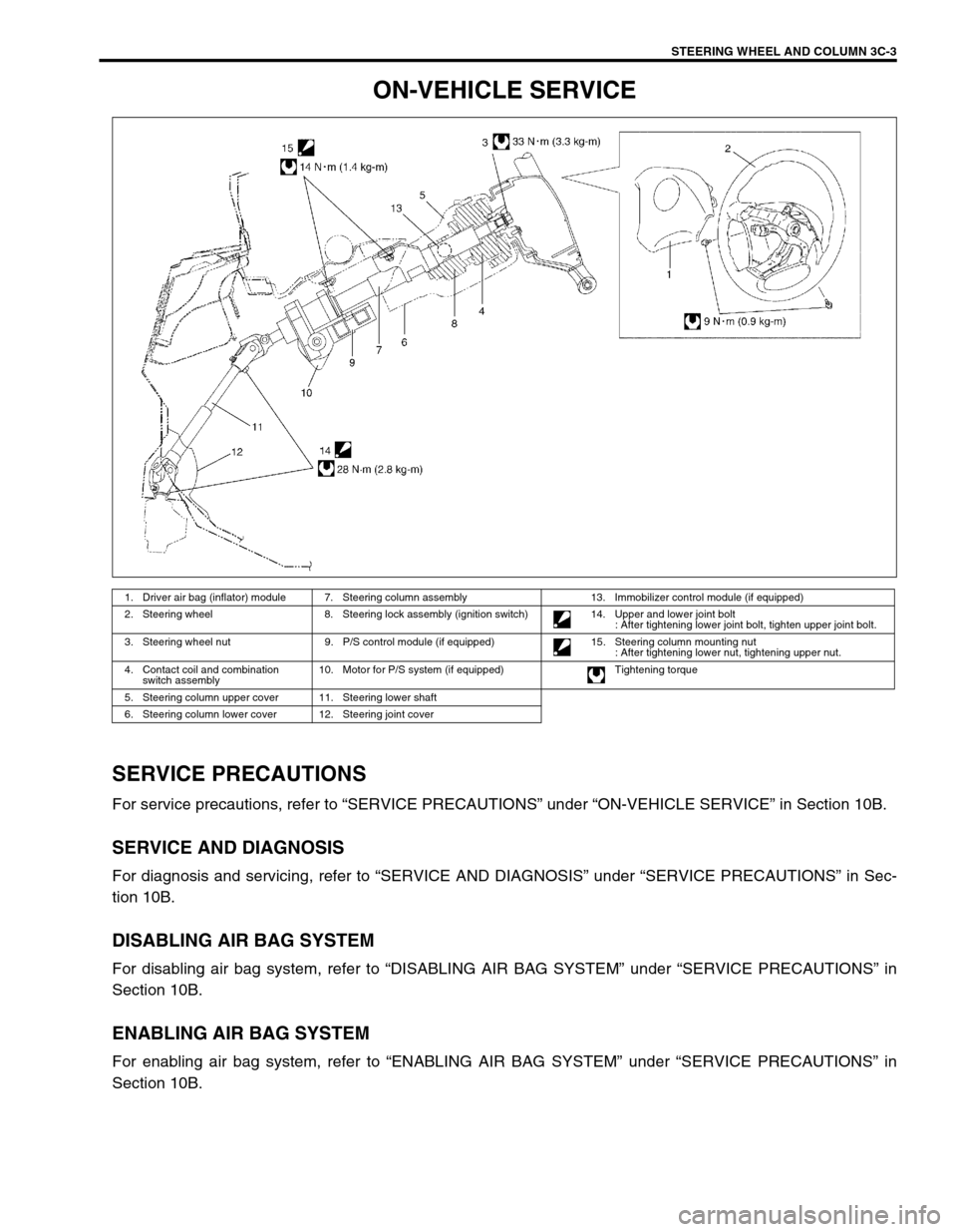
1. Driver air bag (inflator) module 7. Steering column assembly 13. Immobilizer control module (if equipped)
2. Steering wheel 8. Steering lock assembly (ignition switch) 14. Upper and lower joint bolt
: After tightening lower joint bolt, tighten upper joint bolt.
3. Steering wheel nut 9. P/S control module (if equipped) 15. Steering column mounting nut
: After tightening lower nut, tightening upper nut.
4. Contact coil and combination
switch assembly10. Motor for P/S system (if equipped) Tightening torque
5. Steering column upper cover 11. Steering lower shaft
6. Steering column lower cover 12. Steering joint cover
Page 179 of 698
3C-6 STEERING WHEEL AND COLUMN
STEERING WHEEL
REMOVAL
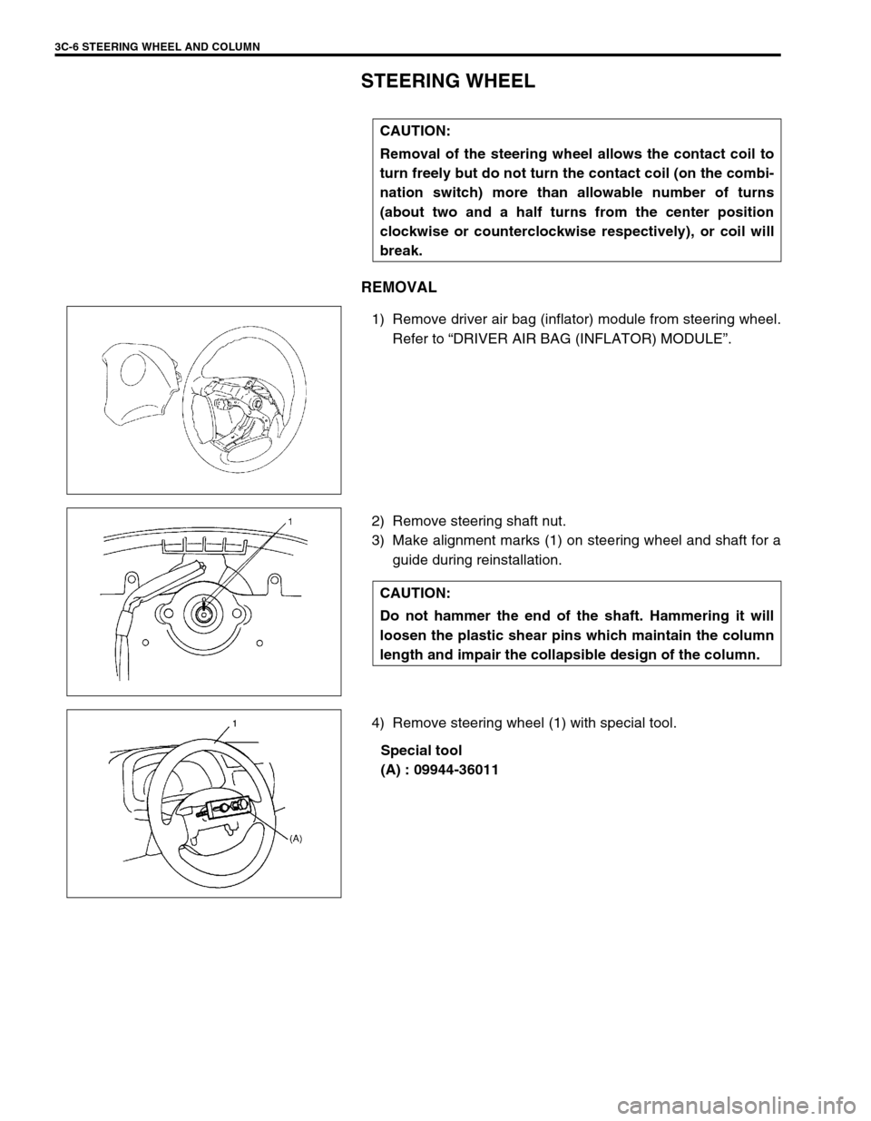
1) Remove driver air bag (inflator) module from steering wheel.
Refer to “DRIVER AIR BAG (INFLATOR) MODULE”.
2) Remove steering shaft nut.
3) Make alignment marks (1) on steering wheel and shaft for a
guide during reinstallation.
4) Remove steering wheel (1) with special tool.
Special tool
(A) : 09944-36011 CAUTION:
Removal of the steering wheel allows the contact coil to
turn freely but do not turn the contact coil (on the combi-
nation switch) more than allowable number of turns
(about two and a half turns from the center position
clockwise or counterclockwise respectively), or coil will
break.
CAUTION:
Do not hammer the end of the shaft. Hammering it will
loosen the plastic shear pins which maintain the column
length and impair the collapsible design of the column.