Stop light SUZUKI SWIFT 2000 1.G RG413 Service Workshop Manual
[x] Cancel search | Manufacturer: SUZUKI, Model Year: 2000, Model line: SWIFT, Model: SUZUKI SWIFT 2000 1.GPages: 698, PDF Size: 16.01 MB
Page 45 of 698
0B-16 MAINTENANCE AND LUBRICATION
3) Check steering linkage for looseness and damage. Repair or
replace defective parts, if any.
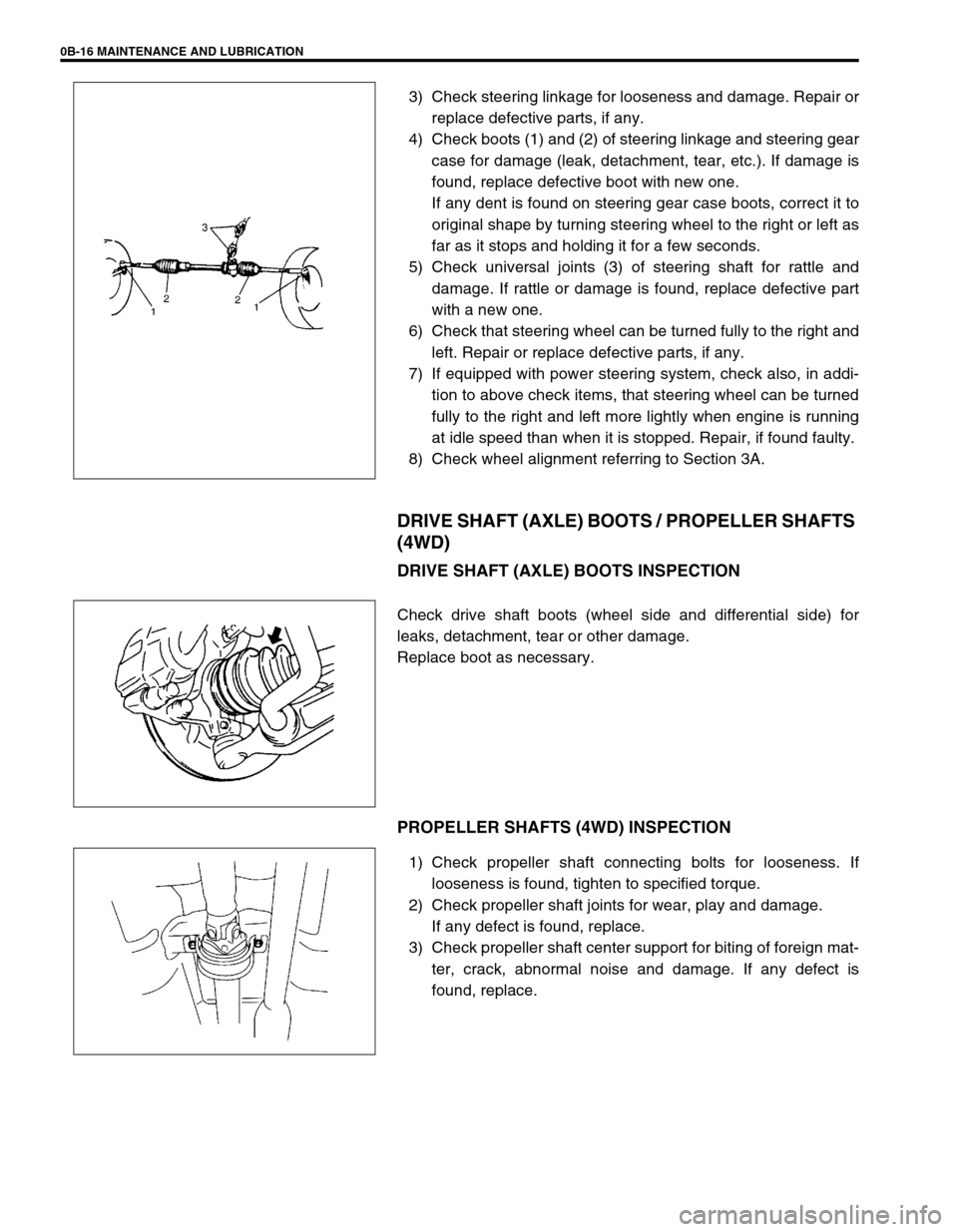
4) Check boots (1) and (2) of steering linkage and steering gear
case for damage (leak, detachment, tear, etc.). If damage is
found, replace defective boot with new one.
If any dent is found on steering gear case boots, correct it to
original shape by turning steering wheel to the right or left as
far as it stops and holding it for a few seconds.
5) Check universal joints (3) of steering shaft for rattle and
damage. If rattle or damage is found, replace defective part
with a new one.
6) Check that steering wheel can be turned fully to the right and
left. Repair or replace defective parts, if any.
7) If equipped with power steering system, check also, in addi-
tion to above check items, that steering wheel can be turned
fully to the right and left more lightly when engine is running
at idle speed than when it is stopped. Repair, if found faulty.
8) Check wheel alignment referring to Section 3A.
DRIVE SHAFT (AXLE) BOOTS / PROPELLER SHAFTS
(4WD)
DRIVE SHAFT (AXLE) BOOTS INSPECTION
Check drive shaft boots (wheel side and differential side) for
leaks, detachment, tear or other damage.
Replace boot as necessary.
PROPELLER SHAFTS (4WD) INSPECTION
1) Check propeller shaft connecting bolts for looseness. If
looseness is found, tighten to specified torque.
2) Check propeller shaft joints for wear, play and damage.
If any defect is found, replace.
3) Check propeller shaft center support for biting of foreign mat-
ter, crack, abnormal noise and damage. If any defect is
found, replace.
Page 73 of 698
1B-8 AIR CONDITIONING (OPTIONAL)
ABNORMAL NOISE FROM CRANKSHAFT PULLEY
ABNORMAL NOISE FROM TENSION PULLEY
ABNORMAL NOISE FROM A/C EVAPORATOR
ABNORMAL NOISE FROM BLOWER FAN MOTOR
Condition Possible Cause Correction
A large rattling noise
is heard at idle or sud-
den acceleration.Loosen crankshaft pulley bolt Retighten bolt.
Condition Possible Cause Correction
Clattering noise is
heard from pulley.Worn or damaged bearing Replace tension pulley.
Pulley cranks upon
contact.Cracked or loose bracket Replace or retighten bracket.
Condition Possible Cause Correction
Whistling sound is
heard from A/C evapo-
rator.Depending on the combination of the interior/
exterior temperatures, engine rpm and refriger-
ant pressure, the refrigerant flowing out of the
expansion valve may, under certain conditions,
make a whistling soundAt times, slightly decreasing refrig-
erant volume may stop this noise.
Inspect expansion valve and
replace if faulty.
Condition Possible Cause Correction
Blower fan motor
emits a chirping
sound in proportion to
its speed of rotation.Worn or damaged motor brushes or commuta-
torRepair or replace blower fan motor.
Fluttering noise or
large droning noise is
heard from blower fan
motor.Leaves or other debris introduced from fresh air
inlet to blower fan motorRemove debris and make sure that
the screen at fresh air inlet is intact.
Page 85 of 698
1B-20 AIR CONDITIONING (OPTIONAL)
REFRIGERANT RECOVERY, EVACUATING AND CHARGING
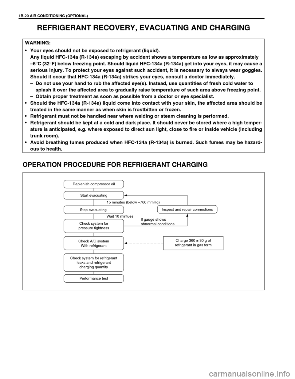
OPERATION PROCEDURE FOR REFRIGERANT CHARGING
WARNING:
Your eyes should not be exposed to refrigerant (liquid).
Any liquid HFC-134a (R-134a) escaping by accident shows a temperature as low as approximately
–6°C (32°F) below freezing point. Should liquid HFC-134a (R-134a) get into your eyes, it may cause a
serious injury. To protect your eyes against such accident, it is necessary to always wear goggles.
Should it occur that HFC-134a (R-134a) strikes your eyes, consult a doctor immediately.
– Do not use your hand to rub the affected eye(s). Instead, use quantities of fresh cold water to
splash it over the affected area to gradually raise temperature of such area above freezing point.
– Obtain proper treatment as soon as possible from a doctor or eye specialist.
Should the HFC-134a (R-134a) liquid come into contact with your skin, the affected area should be
treated in the same manner as when skin is frostbitten or frozen.
Refrigerant must not be handled near where welding or steam cleaning is performed.
Refrigerant should be kept at a cold and dark place. It should never be stored where a high temper-
ature is anticipated, e.g. where exposed to direct sun light, close to fire or inside vehicle (including
trunk room).
Avoid breathing fumes produced when HFC-134a (R-134a) is burned. Such fumes may be hazard-
ous to health.
Replenish compressor oil
Start evacuating
Inspect and repair connections
Charge 360 ± 30 g of
refrigerant in gas form Stop evacuating 15 minutes (below –760 mmHg)
Wait 10 mintues
If gauge shows
abnormal conditions Check system for
pressure tightness
Check A/C system
With refrigerant
Check system for refrigerant
leaks and refrigerant
charging quantity
Performance test
Page 101 of 698
1B-36 AIR CONDITIONING (OPTIONAL)
A/C SWITCH
REMOVAL AND INSTALLATION
Refer to “HEATER CONTROL ASSEMBLY” in Section 1A.
INSPECTION
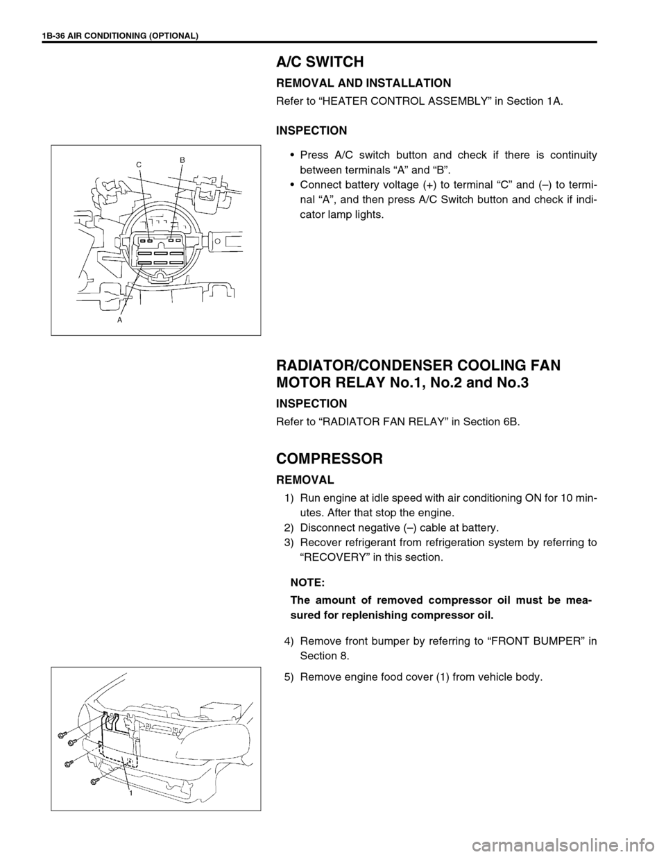
Press A/C switch button and check if there is continuity
between terminals “A” and “B”.
Connect battery voltage (+) to terminal “C” and (–) to termi-
nal “A”, and then press A/C Switch button and check if indi-
cator lamp lights.
RADIATOR/CONDENSER COOLING FAN
MOTOR RELAY No.1, No.2 and No.3
INSPECTION
Refer to “RADIATOR FAN RELAY” in Section 6B.
COMPRESSOR
REMOVAL
1) Run engine at idle speed with air conditioning ON for 10 min-
utes. After that stop the engine.
2) Disconnect negative (–) cable at battery.
3) Recover refrigerant from refrigeration system by referring to
“RECOVERY” in this section.
4) Remove front bumper by referring to “FRONT BUMPER” in
Section 8.
5) Remove engine food cover (1) from vehicle body.
NOTE:
The amount of removed compressor oil must be mea-
sured for replenishing compressor oil.
Page 145 of 698
3B1-4 ELECTRICAL POWER STEERING (P/S) SYSTEM
DIAGNOSIS
The P/S system in this vehicle is controlled by P/S control module. P/S control module has an on-board diagnos-
tic system which detects a malfunction in this system.
When diagnosing troubles, be sure to have full understanding of the outline of “ON-BOARD DIAGNOSTIC SYS-
TEM” and each item in “PRECAUTION IN DIAGNOSING TROUBLE” and execute diagnosis according to “SYS-
TEM CHECK FLOW TABLE”.
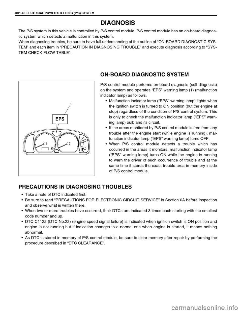
ON-BOARD DIAGNOSTIC SYSTEM
P/S control module performs on-board diagnosis (self-diagnosis)
on the system and operates “EPS” warning lamp (1) (malfunction
indicator lamp) as follows.
Malfunction indicator lamp (“EPS” warning lamp) lights when
the ignition switch is turned to ON position (but the engine at
stop) regardless of the condition of P/S control system. This
is only to check the malfunction indicator lamp (“EPS” warn-
ing lamp) bulb and its circuit.
If the areas monitored by P/S control module is free from any
trouble after the engine start (while engine is running), mal-
function indicator lamp (“EPS” warning lamp) turns OFF.
When P/S control module detects a trouble which has
occurred in the areas it monitors, malfunction indicator lamp
(“EPS” warning lamp) turns ON while the engine is running
to warn the driver of such occurrence of trouble and at the
same time it stores the exact trouble area in memory inside
of P/S control module.
PRECAUTIONS IN DIAGNOSING TROUBLES
Take a note of DTC indicated first.
Be sure to read “PRECAUTIONS FOR ELECTRONIC CIRCUIT SERVICE” in Section 0A before inspection
and observe what is written there.
When two or more troubles have occurred, their DTCs are indicated 3 times each starting with the smallest
code number and up.
DTC C1122 (DTC No.22) (engine speed signal failure) is indicated when ignition switch is ON position and
engine is not running but if indication changes to a normal one when engine is started, it means nothing
abnormal.
As DTC is stored in memory of P/S control module, be sure to clear memory after repair by performing the
procedure described in “DTC CLEARANCE”.
1
Page 274 of 698
BRAKES 5-1
6F1
6F2
6G
6H
6K
7A
7A1
7B1
7C1
7D
7E
7F
8A
8B
8C
5
9
10
10A
10B
SECTION 5
BRAKES
CONTENTS
GENERAL DESCRIPTION ................................ 5-2
DIAGNOSIS ....................................................... 5-4
ROAD TESTING BRAKES ............................. 5-4
BRAKE FLUID LEAKS ................................... 5-4
SUBSTANDARD OR CONTAMINATED
BRAKE FLUID ................................................ 5-4
DIAGNOSIS TABLE ....................................... 5-5
BRAKE PEDAL FREE HEIGHT
ADJUSTMENT ............................................... 5-8
BRAKE PEDAL PLAY INSPECTION ............. 5-8
STOP LIGHT SWITCH ADJUSTMENT.......... 5-8
EXCESSIVE PEDAL TRAVEL
INSPECTION ................................................. 5-9
FRONT BRAKE PAD INSPECTION .............. 5-9
BRAKE DISC INSPECTION........................... 5-9
PARKING BRAKE INSPECTION AND
ADJUSTMENT ............................................. 5-10
BOOSTER OPERATION INSPECTION....... 5-11
FLUID PRESSURE TEST (IF EQUIPPED
WITH LSPV) ................................................ 5-12
MASTER CYLINDER AND BRAKE FLUID
LEVEL INSPECTION ................................... 5-14
BRAKE HOSE AND PIPE INSPECTION ..... 5-15
HOSE ....................................................... 5-15
PIPE ......................................................... 5-15
ON-VEHICLE SERVICE .................................. 5-15AIR BLEEDING OF BRAKE SYSTEM ......... 5-15
FRONT BRAKE ........................................... 5-17
BRAKE PAD............................................. 5-17
CALIPER ASSEMBLY ............................. 5-19
BRAKE DISC ........................................... 5-23
REAR BRAKE .............................................. 5-25
BRAKE DRUM ......................................... 5-26
BRAKE SHOE .......................................... 5-29
WHEEL CYLINDER ................................. 5-30
BRAKE BACK PLATE (FOR 2WD
VEHICLE)................................................. 5-31
BRAKE BACK PLATE (FOR 4WD
VEHICLE)................................................. 5-33
MASTER CYLINDER ................................... 5-33
MASTER CYLINDER RESERVOIR ......... 5-33
MASTER CYLINDER ASSEMBLY........... 5-34
BRAKE BOOSTER ...................................... 5-38
BRAKE HOSE/PIPE .................................... 5-41
FRONT BRAKE HOSE/PIPE ................... 5-41
REAR BRAKE HOSE/PIPE...................... 5-44
PARKING BRAKE CABLE ........................... 5-46
LSPV (LOAD SENSING PROPORTIONING
VALVE) ASSEMBLY (IF EQUIPPED).......... 5-48
REQUIRED SERVICE MATERIAL.................. 5-50
SPECIAL TOOL .............................................. 5-50
NOTE:
All front fasteners are important attaching parts in that they could affect the performance of vital parts
and systems, and/or could result in major repair expense. They must be replaced with one of same
part number or with an equivalent part if replacement becomes necessary. Do not use a replacement
part of lesser quality or substitute design. Torque values must be used as specified during reassem-
bly to assure proper retention of all parts. There is to be no welding as it may result in extensive dam-
age and weakening of the metal.
Page 277 of 698
5-4 BRAKES
DIAGNOSIS
ROAD TESTING BRAKES
Brakes should be tested on dry, clean, smooth and reasonably level roadway which is not crowned. Road test
brakes by making brake applications with both light and heavy pedal forces at various speeds to determine if the
vehicle stops evenly and effectively. Also drive vehicle to see if it leads to one side or the other without brake
application. If it does, check the tire pressure, front end alignment and front suspension attachments for loose-
ness. See diagnosis table for other causes.
BRAKE FLUID LEAKS
Check the master cylinder fluid levels. While a slight drop in reservoir level does result from normal lining wear,
an abnormally low level indicates a leak in the system. In such a case, check the entire brake system for leak-
age. If even a slight evidence of leakage is noted, the cause should be corrected or defective parts should be
replaced.
SUBSTANDARD OR CONTAMINATED BRAKE FLUID
Improper brake fluid, mineral oil or water in the fluid may cause the brake fluid to boil or the rubber components
in the hydraulic system to deteriorate.
If primary piston cups are swollen, then rubber parts have deteriorated. This deterioration may also be evi-
denced by swollen wheel cylinder piston cups on the drum brake wheels.
If deterioration of rubber is evident, disassemble all hydraulic parts and wash with alcohol. Dry these parts with
compressed air before assembly to keep alcohol out of the system. Replace all rubber parts in the system,
including hoses. Also, when working on the brake mechanisms, check for fluid on the linings.
If excessive fluid is found, replace the pads.
If master cylinder piston seals are satisfactory, check for leakage or excessive heat conditions. If leakage is not
found, drain fluid, flush with brake fluid, refill and bleed system.
The system must be flushed if there is any doubt as to the grade of fluid in the system or if fluid has been used
which contained parts that have been subjected to contaminated fluid.
Page 281 of 698
5-8 BRAKES
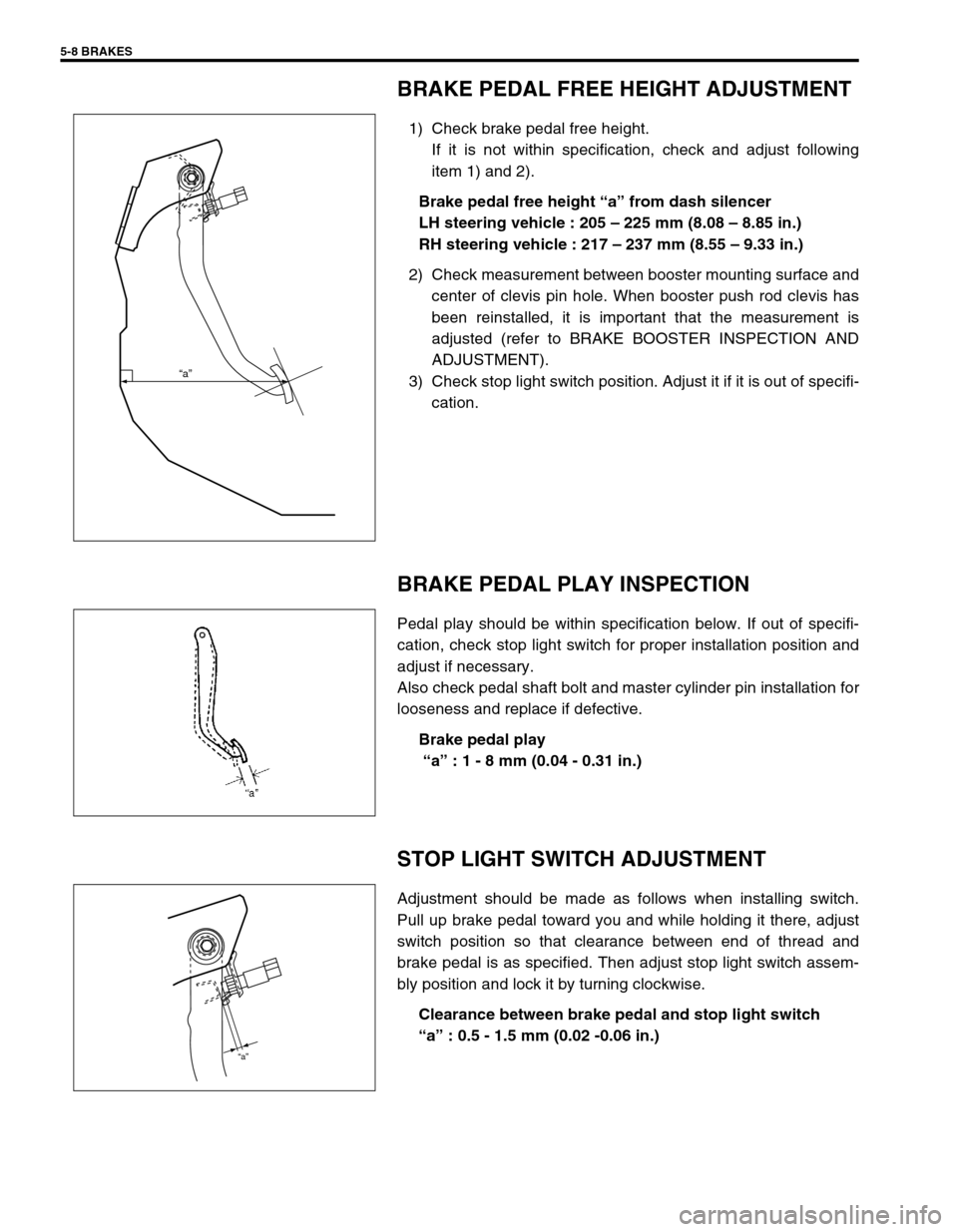
BRAKE PEDAL FREE HEIGHT ADJUSTMENT
1) Check brake pedal free height.
If it is not within specification, check and adjust following
item 1) and 2).
Brake pedal free height “a” from dash silencer
LH steering vehicle : 205 – 225 mm (8.08 – 8.85 in.)
RH steering vehicle : 217 – 237 mm (8.55 – 9.33 in.)
2) Check measurement between booster mounting surface and
center of clevis pin hole. When booster push rod clevis has
been reinstalled, it is important that the measurement is
adjusted (refer to BRAKE BOOSTER INSPECTION AND
ADJUSTMENT).
3) Check stop light switch position. Adjust it if it is out of specifi-
cation.
BRAKE PEDAL PLAY INSPECTION
Pedal play should be within specification below. If out of specifi-
cation, check stop light switch for proper installation position and
adjust if necessary.
Also check pedal shaft bolt and master cylinder pin installation for
looseness and replace if defective.
Brake pedal play
“a” : 1 - 8 mm (0.04 - 0.31 in.)
STOP LIGHT SWITCH ADJUSTMENT
Adjustment should be made as follows when installing switch.
Pull up brake pedal toward you and while holding it there, adjust
switch position so that clearance between end of thread and
brake pedal is as specified. Then adjust stop light switch assem-
bly position and lock it by turning clockwise.
Clearance between brake pedal and stop light switch
“a” : 0.5 - 1.5 mm (0.02 -0.06 in.)
“a”
“a”
Page 328 of 698
ANTILOCK BRAKE SYSTEM (ABS) 5E-3
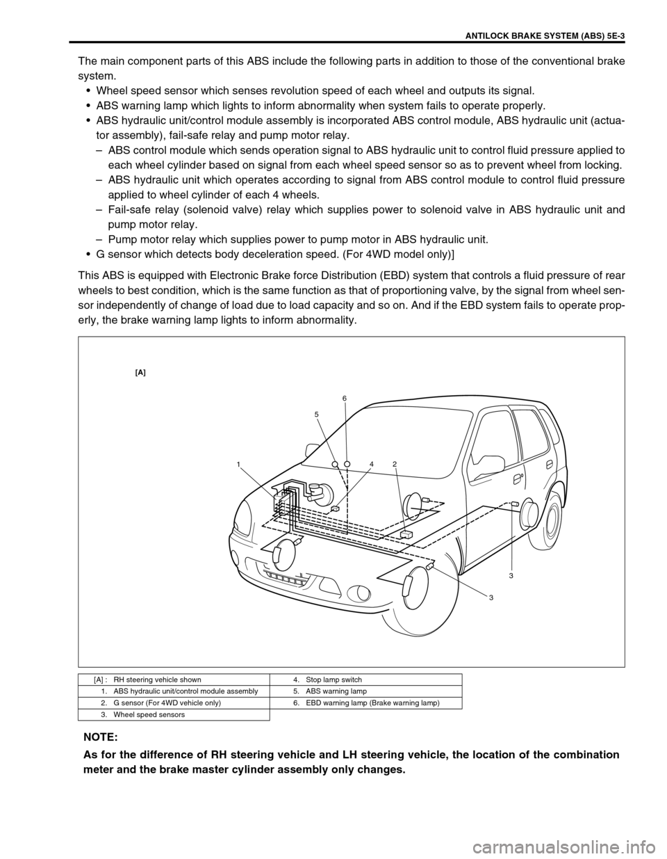
The main component parts of this ABS include the following parts in addition to those of the conventional brake
system.
Wheel speed sensor which senses revolution speed of each wheel and outputs its signal.
ABS warning lamp which lights to inform abnormality when system fails to operate properly.
ABS hydraulic unit/control module assembly is incorporated ABS control module, ABS hydraulic unit (actua-
tor assembly), fail-safe relay and pump motor relay.
–ABS control module which sends operation signal to ABS hydraulic unit to control fluid pressure applied to
each wheel cylinder based on signal from each wheel speed sensor so as to prevent wheel from locking.
–ABS hydraulic unit which operates according to signal from ABS control module to control fluid pressure
applied to wheel cylinder of each 4 wheels.
–Fail-safe relay (solenoid valve) relay which supplies power to solenoid valve in ABS hydraulic unit and
pump motor relay.
–Pump motor relay which supplies power to pump motor in ABS hydraulic unit.
G sensor which detects body deceleration speed. (For 4WD model only)]
This ABS is equipped with Electronic Brake force Distribution (EBD) system that controls a fluid pressure of rear
wheels to best condition, which is the same function as that of proportioning valve, by the signal from wheel sen-
sor independently of change of load due to load capacity and so on. And if the EBD system fails to operate prop-
erly, the brake warning lamp lights to inform abnormality.
[A] : RH steering vehicle shown 4. Stop lamp switch
1. ABS hydraulic unit/control module assembly 5. ABS warning lamp
2. G sensor (For 4WD vehicle only) 6. EBD warning lamp (Brake warning lamp)
3. Wheel speed sensors
156
2 4
33
[A]
NOTE:
As for the difference of RH steering vehicle and LH steering vehicle, the location of the combination
meter and the brake master cylinder assembly only changes.
Page 332 of 698
ANTILOCK BRAKE SYSTEM (ABS) 5E-7
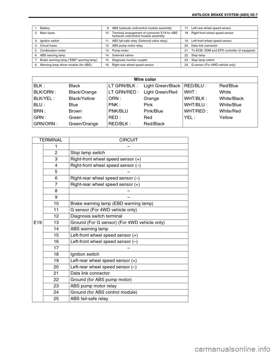
1. Battery 9. ABS hydraulic unit/control module assembly 17. Left-rear wheel speed sensor
2. Main fuses 10. Terminal arrangement of connector E19 for ABS
hydraulic unit/control module assembly18. Right-front wheel speed sensor
3. Ignition switch 11. ABS fail-safe relay (Solenoid valve relay) 19. Left-front wheel speed sensor
4. Circuit fuses 12. ABS pump motor relay 20. Data link connector
5. Combination meter 13. Pump motor 21. To ECM, SDM and EPS controller (if equipped)
6. ABS warning lamp 14. Solenoid valves 22. Stop lamp
7. Brake warning lamp (“EBD” warning lamp) 15. Diagnosis monitor coupler 23. Stop lamp switch
8. Warning lamp driver module (for ABS) 16. Right-rear wheel speed sensor 24. G sensor (For 4WD vehicle only)
Wire color
BLK : Black LT GRN/BLK : Light Green/Black RED/BLU : Red/Blue
BLK/ORN : Black/Orange LT GRN/RED : Light Green/Red WHT : White
BLK/YEL : Black/Yellow ORN : Orange WHT/BLK : White/Black
BLU : Blue PNK : Pink WHT/BLU : White/Blue
BRN : Brown PNK/BLU Pink/Blue WHT/RED : White/Red
GRN : Green RED : Red YEL : Yellow
GRN/ORN : Green/Orange RED/BLK : Red/Black
TERMINAL CIRCUIT
E191–
2 Stop lamp switch
3 Right-front wheel speed sensor (+)
4 Right-front wheel speed sensor (–)
5–
6 Right-rear wheel speed sensor (–)
7 Right-rear wheel speed sensor (+)
8–
9–
10 Brake warning lamp (EBD warning lamp)
11 G sensor (For 4WD vehicle only)
12 Diagnosis switch terminal
13 Ground (For G sensor) (For 4WD vehicle only)
14 ABS warning lamp
15 Left-front wheel speed sensor (+)
16 Left-front wheel speed sensor (–)
17–
18 Ignition switch
19 Left-rear wheel speed sensor (+)
20 Left-rear wheel speed sensor (–)
21 Data link connector
22 Ground (for ABS pump motor)
23 ABS pump motor relay
24 Ground (for ABS control module)
25 ABS fail-safe relay