lock SUZUKI SWIFT 2000 1.G RG413 Service Workshop Manual
[x] Cancel search | Manufacturer: SUZUKI, Model Year: 2000, Model line: SWIFT, Model: SUZUKI SWIFT 2000 1.GPages: 698, PDF Size: 16.01 MB
Page 3 of 698
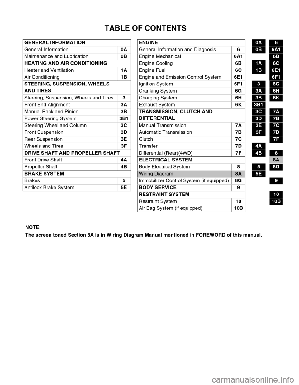
TABLE OF CONTENTS
GENERAL INFORMATION ENGINE0A6
General Information0A
General Information and Diagnosis6
0B6A1
Maintenance and Lubrication0B
Engine Mechanical6A1
6B
HEATING AND AIR CONDITIONING
Engine Cooling6B
1A6C
Heater and Ventilation1A
Engine Fuel6C
1B6E1
Air Conditioning1B
Engine and Emission Control System6E1
6F1
STEERING, SUSPENSION, WHEELS
AND TIRESIgnition System6F1
36G
Cranking System6G
3A6H
Steering, Suspension, Wheels and Tires3
Charging System6H
3B6K
Front End Alignment3A
Exhaust System6K
3B1 6B
Manual Rack and Pinion3B TRANSMISSION, CLUTCH AND
DIFFERENTIAL
3C7A
Power Steering System3B1
3D7B
Steering Wheel and Column3C
Manual Transmission7A
3E7C
Front Suspension3D
Automatic Transmission7B
3F7D
Rear Suspension3E
Clutch7C
7F
Wheels and Tires3F
Transfer7D
4A
DRIVE SHAFT AND PROPELLER SHAFT
Differential (Rear)(4WD)7F
4B8
Front Drive Shaft 4A ELECTRICAL SYSTEM
8A
Propeller Shaft4B
Body Electrical System8
58G
BRAKE SYSTEM
Wiring Diagram8A5E
Brakes5
Immobilizer Control System (if equipped)8G
9
Antilock Brake System5E BODY SERVICE 9
RESTRAINT SYSTEM
10
Restraint System10
10B
Air Bag System (if equipped)10B
NOTE:
The screen toned Section 8A is in Wiring Diagram Manual mentioned in FOREWORD of this manual.
Page 10 of 698
GENERAL INFORMATION 0A-7
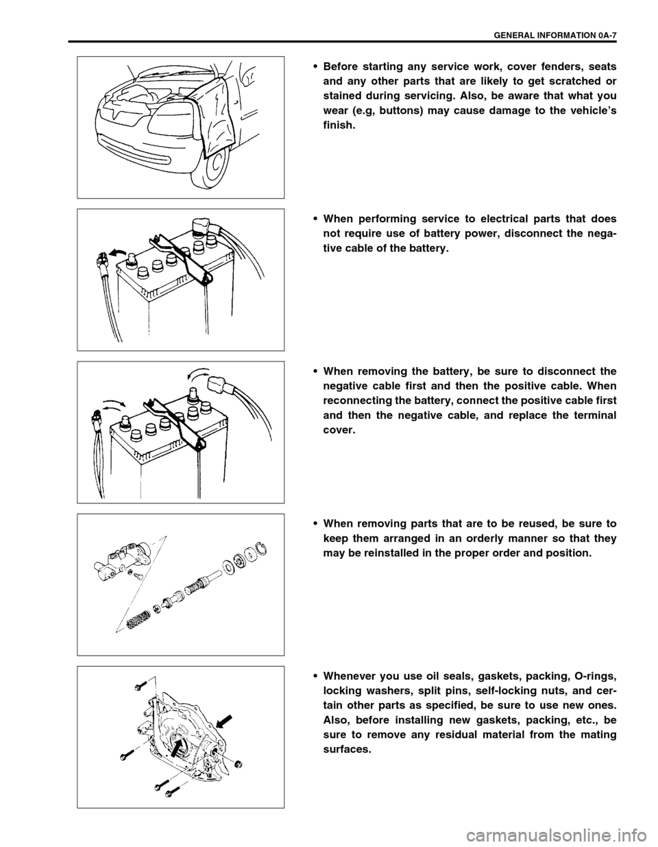
Before starting any service work, cover fenders, seats
and any other parts that are likely to get scratched or
stained during servicing. Also, be aware that what you
wear (e.g, buttons) may cause damage to the vehicle’s
finish.
When performing service to electrical parts that does
not require use of battery power, disconnect the nega-
tive cable of the battery.
When removing the battery, be sure to disconnect the
negative cable first and then the positive cable. When
reconnecting the battery, connect the positive cable first
and then the negative cable, and replace the terminal
cover.
When removing parts that are to be reused, be sure to
keep them arranged in an orderly manner so that they
may be reinstalled in the proper order and position.
Whenever you use oil seals, gaskets, packing, O-rings,
locking washers, split pins, self-locking nuts, and cer-
tain other parts as specified, be sure to use new ones.
Also, before installing new gaskets, packing, etc., be
sure to remove any residual material from the mating
surfaces.
Page 14 of 698
GENERAL INFORMATION 0A-11
PRECAUTIONS FOR ELECTRICAL CIRCUIT
SERVICE
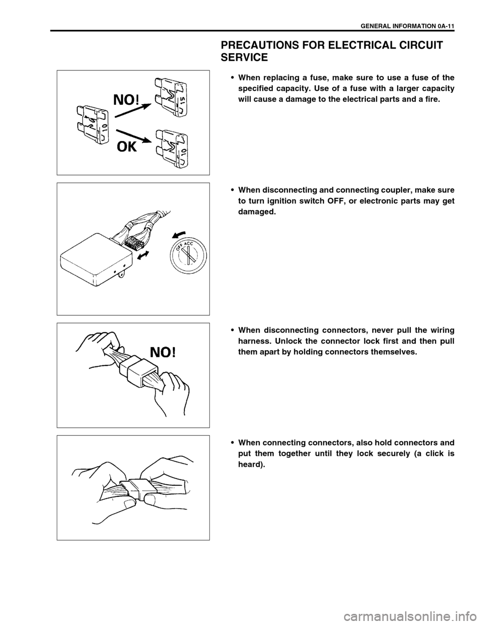
When replacing a fuse, make sure to use a fuse of the
specified capacity. Use of a fuse with a larger capacity
will cause a damage to the electrical parts and a fire.
When disconnecting and connecting coupler, make sure
to turn ignition switch OFF, or electronic parts may get
damaged.
When disconnecting connectors, never pull the wiring
harness. Unlock the connector lock first and then pull
them apart by holding connectors themselves.
When connecting connectors, also hold connectors and
put them together until they lock securely (a click is
heard).
Page 16 of 698
GENERAL INFORMATION 0A-13
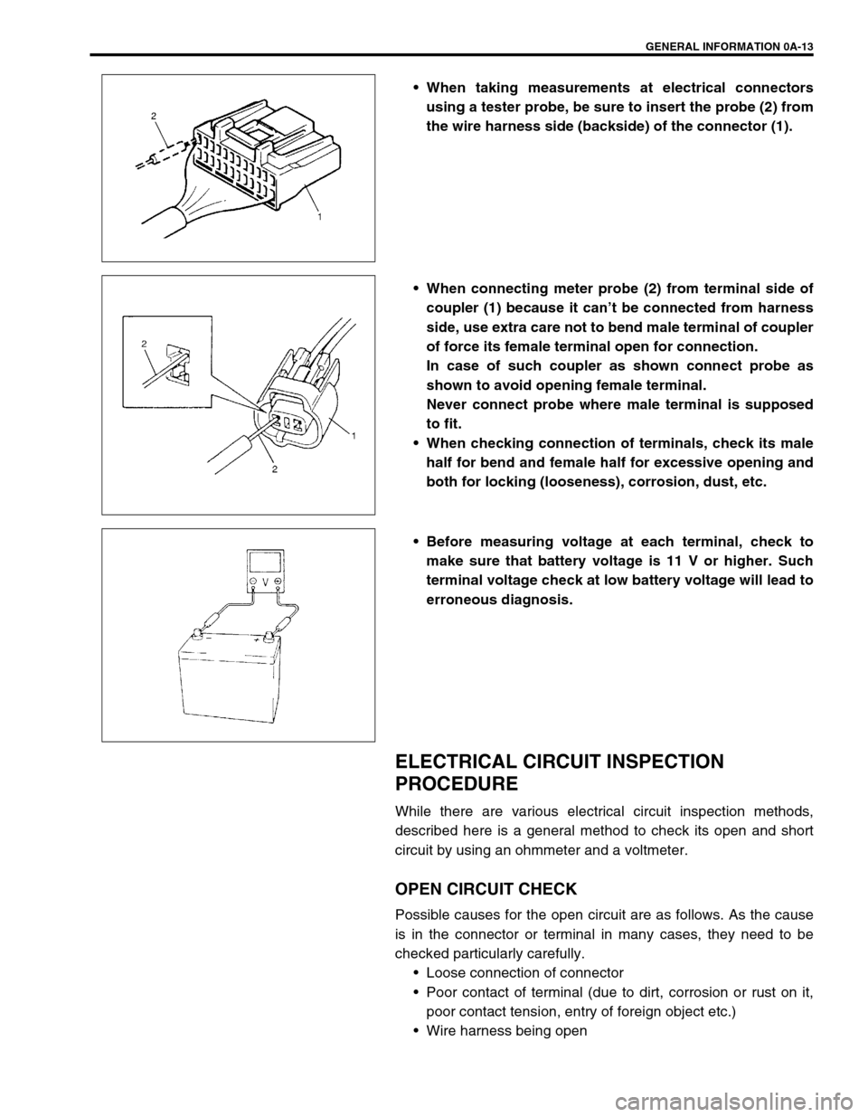
When taking measurements at electrical connectors
using a tester probe, be sure to insert the probe (2) from
the wire harness side (backside) of the connector (1).
When connecting meter probe (2) from terminal side of
coupler (1) because it can’t be connected from harness
side, use extra care not to bend male terminal of coupler
of force its female terminal open for connection.
In case of such coupler as shown connect probe as
shown to avoid opening female terminal.
Never connect probe where male terminal is supposed
to fit.
When checking connection of terminals, check its male
half for bend and female half for excessive opening and
both for locking (looseness), corrosion, dust, etc.
Before measuring voltage at each terminal, check to
make sure that battery voltage is 11 V or higher. Such
terminal voltage check at low battery voltage will lead to
erroneous diagnosis.
ELECTRICAL CIRCUIT INSPECTION
PROCEDURE
While there are various electrical circuit inspection methods,
described here is a general method to check its open and short
circuit by using an ohmmeter and a voltmeter.
OPEN CIRCUIT CHECK
Possible causes for the open circuit are as follows. As the cause
is in the connector or terminal in many cases, they need to be
checked particularly carefully.
Loose connection of connector
Poor contact of terminal (due to dirt, corrosion or rust on it,
poor contact tension, entry of foreign object etc.)
Wire harness being open
Page 17 of 698
0A-14 GENERAL INFORMATION
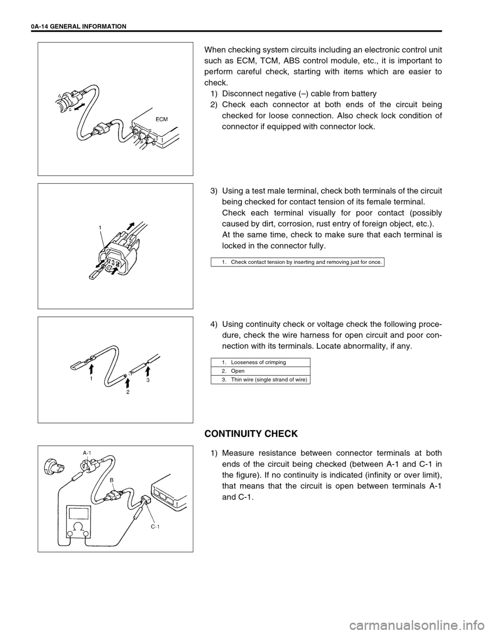
When checking system circuits including an electronic control unit
such as ECM, TCM, ABS control module, etc., it is important to
perform careful check, starting with items which are easier to
check.
1) Disconnect negative (–) cable from battery
2) Check each connector at both ends of the circuit being
checked for loose connection. Also check lock condition of
connector if equipped with connector lock.
3) Using a test male terminal, check both terminals of the circuit
being checked for contact tension of its female terminal.
Check each terminal visually for poor contact (possibly
caused by dirt, corrosion, rust entry of foreign object, etc.).
At the same time, check to make sure that each terminal is
locked in the connector fully.
4) Using continuity check or voltage check the following proce-
dure, check the wire harness for open circuit and poor con-
nection with its terminals. Locate abnormality, if any.
CONTINUITY CHECK
1) Measure resistance between connector terminals at both
ends of the circuit being checked (between A-1 and C-1 in
the figure). If no continuity is indicated (infinity or over limit),
that means that the circuit is open between terminals A-1
and C-1.
1. Check contact tension by inserting and removing just for once.
1. Looseness of crimping
2. Open
3. Thin wire (single strand of wire)
Page 21 of 698
0A-18 GENERAL INFORMATION
IDENTIFICATION INFORMATION
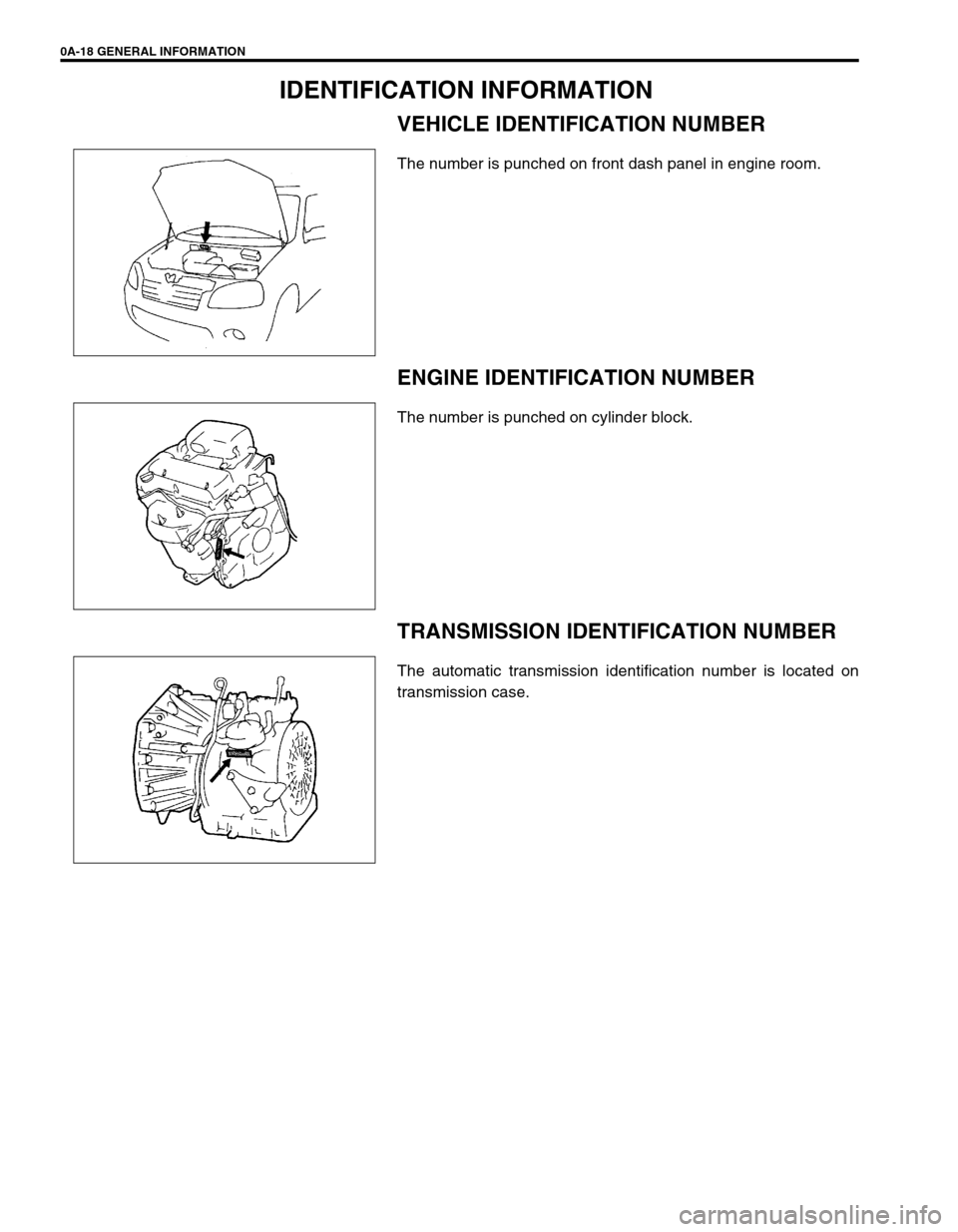
VEHICLE IDENTIFICATION NUMBER
The number is punched on front dash panel in engine room.
ENGINE IDENTIFICATION NUMBER
The number is punched on cylinder block.
TRANSMISSION IDENTIFICATION NUMBER
The automatic transmission identification number is located on
transmission case.
Page 23 of 698
0A-20 GENERAL INFORMATION
VEHICLE LIFTING POINTS
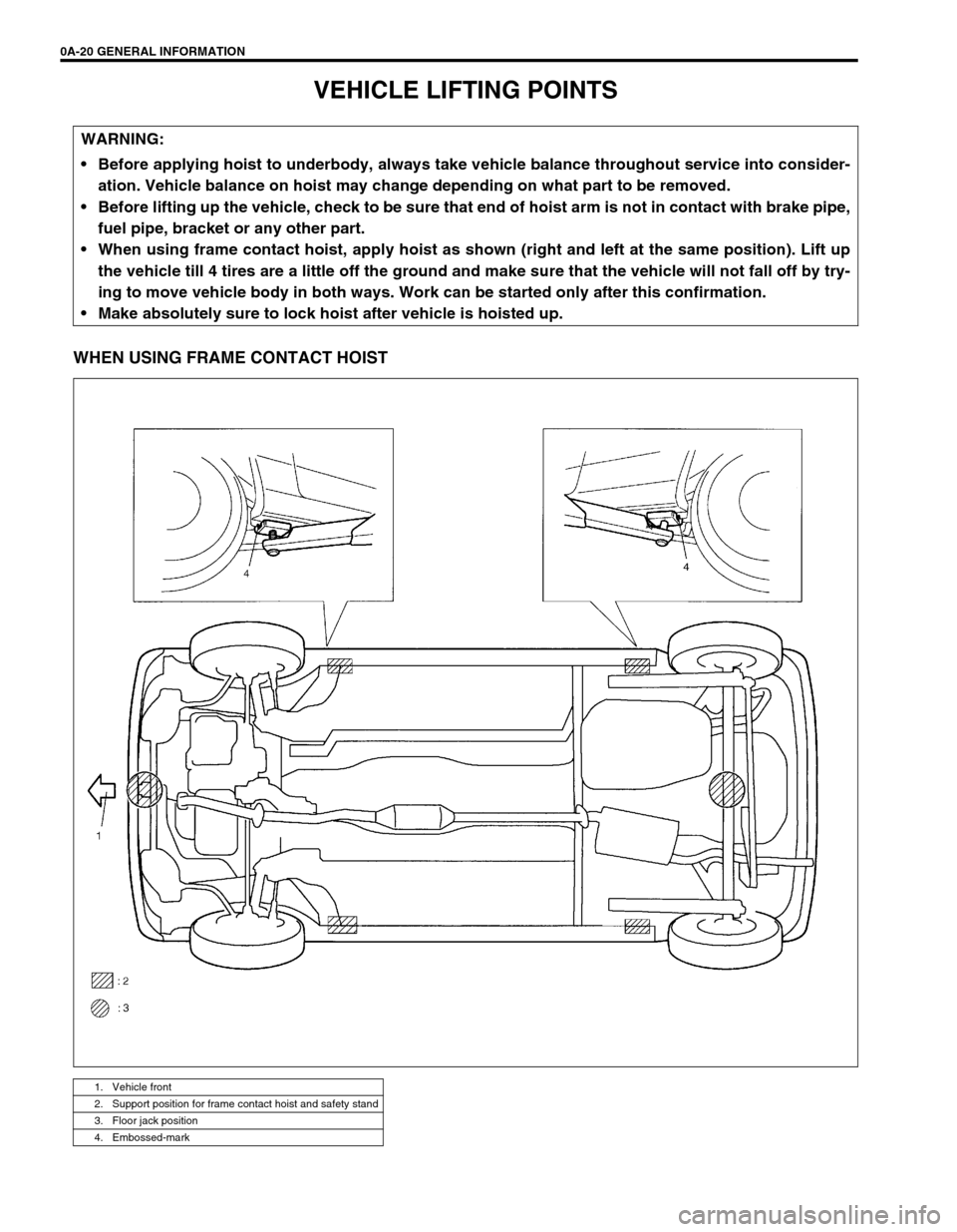
WHEN USING FRAME CONTACT HOIST
WARNING:
Before applying hoist to underbody, always take vehicle balance throughout service into consider-
ation. Vehicle balance on hoist may change depending on what part to be removed.
Before lifting up the vehicle, check to be sure that end of hoist arm is not in contact with brake pipe,
fuel pipe, bracket or any other part.
When using frame contact hoist, apply hoist as shown (right and left at the same position). Lift up
the vehicle till 4 tires are a little off the ground and make sure that the vehicle will not fall off by try-
ing to move vehicle body in both ways. Work can be started only after this confirmation.
Make absolutely sure to lock hoist after vehicle is hoisted up.
1. Vehicle front
2. Support position for frame contact hoist and safety stand
3. Floor jack position
4. Embossed-mark
Page 24 of 698
GENERAL INFORMATION 0A-21
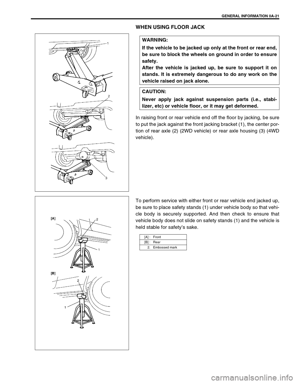
WHEN USING FLOOR JACK
In raising front or rear vehicle end off the floor by jacking, be sure
to put the jack against the front jacking bracket (1), the center por-
tion of rear axle (2) (2WD vehicle) or rear axle housing (3) (4WD
vehicle).
To perform service with either front or rear vehicle end jacked up,
be sure to place safety stands (1) under vehicle body so that vehi-
cle body is securely supported. And then check to ensure that
vehicle body does not slide on safety stands (1) and the vehicle is
held stable for safety’s sake. WARNING:
If the vehicle to be jacked up only at the front or rear end,
be sure to block the wheels on ground in order to ensure
safety.
After the vehicle is jacked up, be sure to support it on
stands. It is extremely dangerous to do any work on the
vehicle raised on jack alone.
CAUTION:
Never apply jack against suspension parts (i.e., stabi-
lizer, etc) or vehicle floor, or it may get deformed.
[A] : Front
[B] : Rear
2. Embossed mark
Page 25 of 698
0A-22 GENERAL INFORMATION
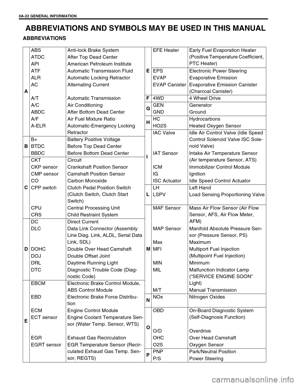
ABBREVIATIONS AND SYMBOLS MAY BE USED IN THIS MANUAL
ABBREVIATIONS
AABS Anti-lock Brake System
EEFE Heater Early Fuel Evaporation Heater
(Positive Temperature Coefficient,
PTC Heater) ATDC After Top Dead Center
API American Petroleum Institute
ATF Automatic Transmission Fluid EPS Electronic Power Steering
ALR Automatic Locking Retractor EVAP Evaporative Emission
AC Alternating Current EVAP Canister Evaporative Emission Canister
(Charcoal Canister)
A/T Automatic TransmissionF
4WD 4 Wheel Drive
A/C Air Conditioning
GGEN Generator
ABDC After Bottom Dead Center GND Ground
A/F Air Fuel Mixture Ratio
HHC Hydrocarbons
A-ELR Automatic-Emergency Locking
RetractorHO2S Heated Oxygen Sensor
IIAC Valve Idle Air Control Valve (Idle Speed
Control Solenoid Valve ISC Sole-
noid Valve)
BB+ Battery Positive Voltage
BTDC Before Top Dead Center
BBDC Before Bottom Dead Center IAT Sensor Intake Air Temperature Sensor
(Air temperature Sensor, ATS)
CCKT Circuit
CKP sensor Crankshaft Position Sensor ICM Immobilizer Control Module
CMP sensor Camshaft Position Sensor IG Ignition
CO Carbon Monoxide ISC Actuator Idle Speed Control Actuator
CPP switch Clutch Pedal Position Switch
(Clutch Switch, Clutch Start
Switch)LLH Left Hand
LSPV Load Sensing Proportioning Valve
CPU Central Processing Unit
MMAF Sensor Mass Air Flow Sensor (Air Flow
Sensor, AFS, Air Flow Meter,
AFM) CRS Child Restraint System
DDC Direct Current
DLC Data Link Connector (Assembly
Line Diag. Link, ALDL, Serial Data
Link, SDL)MAP Sensor Manifold Absolute Pressure Sen-
sor (Pressure Sensor, PS)
Max Maximum
DOHC Double Over Head Camshaft MFI Multiport Fuel Injection
(Multipoint Fuel Injection)
DOJ Double Offset Joint
DRL Daytime Running Light MIN Minimum
DTC Diagnostic Trouble Code (Diag-
nostic Code)MIL Malfunction Indicator Lamp
(“SERVICE ENGINE SOON”
Light)
EEBCM Electronic Brake Control Module,
ABS Control Module M/T Manual Transmission
EBD Electronic Brake Force Distribu-
tionNNOx Nitrogen Oxides
ECM Engine Control Module
OOBD On-Board Diagnostic System
(Self-Diagnosis Function)
ECT sensor Engine Coolant Temperature Sen-
sor (Water Temp. Sensor, WTS)
O/D Overdrive
EGR Exhaust Gas Recirculation OHC Over Head Camshaft
EGRT sensor EGR Temperature Sensor (Recir-
culated Exhaust Gas Temp. Sen-
sor, REGTS)O2S Oxygen Sensor
PPNP Park/Neutral Position
P/S Power Steering
Page 27 of 698
0A-24 GENERAL INFORMATION
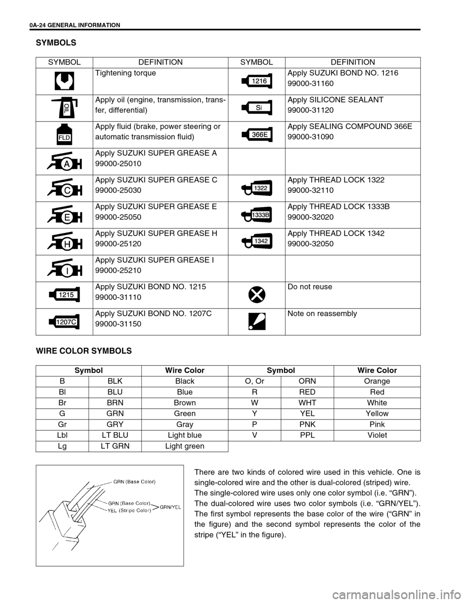
SYMBOLS
WIRE COLOR SYMBOLS
There are two kinds of colored wire used in this vehicle. One is
single-colored wire and the other is dual-colored (striped) wire.
The single-colored wire uses only one color symbol (i.e. “GRN”).
The dual-colored wire uses two color symbols (i.e. “GRN/YEL”).
The first symbol represents the base color of the wire (“GRN” in
the figure) and the second symbol represents the color of the
stripe (“YEL” in the figure). SYMBOL DEFINITION SYMBOL DEFINITION
Tightening torque Apply SUZUKI BOND NO. 1216
99000-31160
Apply oil (engine, transmission, trans-
fer, differential)Apply SILICONE SEALANT
99000-31120
Apply fluid (brake, power steering or
automatic transmission fluid)Apply SEALING COMPOUND 366E
99000-31090
Apply SUZUKI SUPER GREASE A
99000-25010
Apply SUZUKI SUPER GREASE C
99000-25030Apply THREAD LOCK 1322
99000-32110
Apply SUZUKI SUPER GREASE E
99000-25050Apply THREAD LOCK 1333B
99000-32020
Apply SUZUKI SUPER GREASE H
99000-25120Apply THREAD LOCK 1342
99000-32050
Apply SUZUKI SUPER GREASE I
99000-25210
Apply SUZUKI BOND NO. 1215
99000-31110Do not reuse
Apply SUZUKI BOND NO. 1207C
99000-31150Note on reassembly
Symbol Wire Color Symbol Wire Color
B BLK Black O, Or ORN Orange
Bl BLU Blue R RED Red
Br BRN Brown W WHT White
GGRN Green Y YEL Yellow
Gr GRY Gray P PNK Pink
Lbl LT BLU Light blue V PPL Violet
Lg LT GRN Light green