clutch SUZUKI SWIFT 2000 1.G Transmission Service User Guide
[x] Cancel search | Manufacturer: SUZUKI, Model Year: 2000, Model line: SWIFT, Model: SUZUKI SWIFT 2000 1.GPages: 447, PDF Size: 10.54 MB
Page 47 of 447

AUTOMATIC TRANSMISSION (4 A/T) 7B-5
FUNCTIONS
TABLE OF COMPONENT OPERATION
TABLE OF SHIFT SOLENOID VALVE OPERATION
NOTE:
For operation of each part, refer to TABLE OF COMPONENT OPERATION.
PART NAME FUNCTION
Rear clutch Meshes input shaft and rear sun gear through one-way clutch.
Front clutch Meshes input shaft and front internal gear and rear carrier.
Overdrive brake Fixes rear sun gear.
1st & 2nd brake Fixes front sun gear.
Reverse brake Fixes front internal gear and rear carrier.
Direct clutch Meshes input shaft and rear sun gear.
Selector
positionGear
positionPar t
P
R
N
1st
2nd
3rd
4th(O/D)
1st
2nd
1st D
2
LRear
clutchFront
clutchOverdrive
brake1st & 2nd
brakeReverse
brakeDirect
clutchOne-way
clutch
:Operating:Not operating
:Operating:Not operating Range & Gear
P, N
R
D, 21st gear of,
L
1st gear of
2nd gear
3rd gear
4th gearShift Solenoid Valve
A (No.1) B (No.2) C (No.3) D (No.4) E (No.5)
Page 48 of 447
7B-6 AUTOMATIC TRANSMISSION (4 A/T)
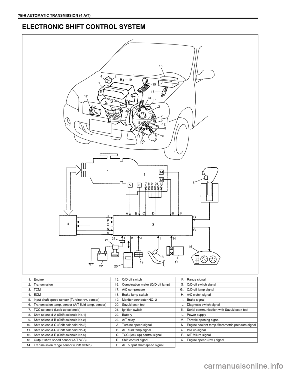
ELECTRONIC SHIFT CONTROL SYSTEM
1. Engine 15. O/D off switch F. Range signal
2. Transmission 16. Combination meter (O/D off lamp) G. O/D off switch signal
3. TCM 17. A/C compressor G’. O/D off lamp signal
4. ECM 18. Brake lamp switch H. A/C clutch signal
5. Input shaft speed sensor (Turbine rev. sensor) 19. Monitor connector NO. 2 I. Brake signal
6. Transmission temp. sensor (A/T fluid temp. sensor) 20. Suzuki scan tool J. Diagnosis switch signal
7. TCC solenoid (Lock-up solenoid) 21. Ignition switch K. Serial communication with Suzuki scan tool
8. Shift solenoid-A (Shift solenoid No.1) 22. Battery L. Power supply
9. Shift solenoid-B (Shift solenoid No.2) 23. A/T relay M. Throttle opening signal
10. Shift solenoid-C (Shift solenoid No.3) A. Turbine speed signal N. Engine coolant temp./Barometric pressure signal
11. Shift solenoid-D (Shift solenoid No.4) B. A/T fluid temp signal O. Idle up signal
12. Shift solenoid-E (Shift solenoid No.5) C. TCC (lock-up) control signal P. A/T failure signal
13. Output shaft speed sensor (A/T VSS) D. Shift control signal Q. Engine speed (rev.) signal.
14. Transmission range sensor (Shift switch) E. A/T output shaft speed signal
14
3
19
15
1816
14 13 5
2
7
9
12
8
6
10 17
11
Page 49 of 447
AUTOMATIC TRANSMISSION (4 A/T) 7B-7
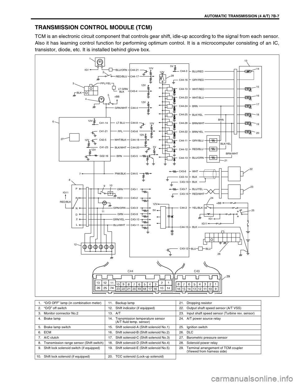
TRANSMISSION CONTROL MODULE (TCM)
TCM is an electronic circuit component that controls gear shift, idle-up according to the signal from each sensor.
Also it has learning control function for performing optimum control. It is a microcomputer consisting of an IC,
transistor, diode, etc. It is installed behind glove box.
1.“O/D OFF” lamp (in combination meter) 11. Backup lamp 21. Dropping resistor
2.“O/D” off switch 12. Shift indicator (if equipped) 22. Output shaft speed sensor (A/T VSS)
3. Monitor connector No.2 13. A/T 23. Input shaft speed sensor (Turbine rev. sensor)
4. Brake lamp 14. Transmission temperature sensor
(A/T fluid temp. sensor)24. A/T power source relay
5. Brake lamp switch 15. Shift solenoid-A (Shift solenoid No.1) 25. Ignition switch
6. ECM 16. Shift solenoid-B (Shift solenoid No.2) 26. DLC
7. A/C clutch 17. Shift solenoid-C (Shift solenoid No.3) 27. Barometric pressure sensor
8. Transmission range sensor (Shift switch) 18. Shift solenoid-D (Shift solenoid No.4) 28. Solenoid power relay
9. Shift lock solenoid switch (if equipped) 19. Shift solenoid-E (Shift solenoid No.5) 29. Terminal arrangement of TCM coupler
(Viewed from harness side)
10. Shift lock solenoid (if equipped) 20. TCC solenoid (Lock-up solenoid)
C41-14
C41-21
C42-5
C41-23
G02-16
BLKBLKLT GRN/ RED/BLU BLU/ORN
PPL/YEL
3
45
+BB
GRN/WHT
LT BLU
PPL
WHT/BLK
BLK/WHT
BRN
PNK/BLK 6
7
8
C44-8
C43-8
C44-18
C44-20
C43-5
C44-5
910
ORN
RED
GRN/ORN RED/BLK
GRNC43-1
C43-2
C43-3
C43-9
C43-10
C43-11 GRN/YEL
BLU/WHT P
R
N
D
2
L11
12C44-21
C44-17
C43-4
C44-4
12V 12V
12V
12V
12V IG1
IG115V
5VC44-3
C44-16
C44-10
C44-23
C44-24
C44-25
C44-26
C44-22
C44-11
C44-12
C44-13
C43-6
C43-14
C43-13
C43-7
C43-15
C44-2
C44-15
C43-12
BLU BLUBLK
BLK BLK
BLU/YEL
YEL/BLK RED/WHT WHT BLU/ORN RED/BLU GRY/BLU
BLK/YEL WHT/BLU
BRN/WHT BRN/WHT BRN WHT/RED
BLK/YEL
BRN/YEL BLU/RED
GRY/RED13
14
15
16
17
19
20 BRN
21
22
23
+BB 24
25
26
12V
12V
12V
12V
18
12V
IG1
IG11
5V
1
2
28
27
Page 61 of 447
AUTOMATIC TRANSMISSION (4 A/T) 7B-19
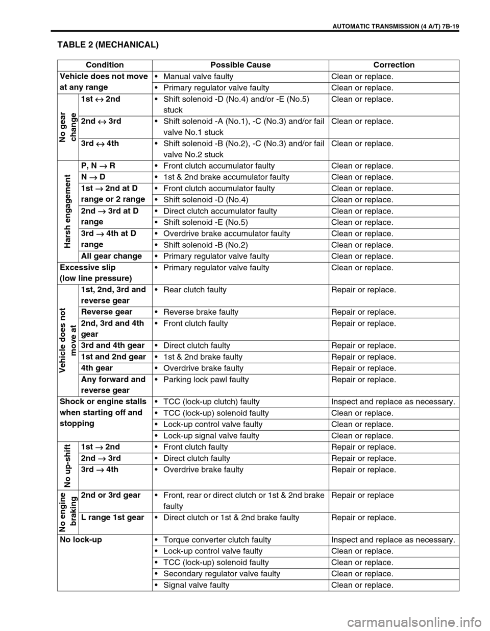
TABLE 2 (MECHANICAL)
Condition Possible Cause Correction
Vehicle does not move
at any rangeManual valve faulty Clean or replace.
Primary regulator valve faulty Clean or replace.
No gear
change
1st
↔
↔↔ ↔ 2nd
Shift solenoid -D (No.4) and/or -E (No.5)
stuck Clean or replace.
2nd
↔
↔↔ ↔ 3rd
Shift solenoid -A (No.1), -C (No.3) and/or fail
valve No.1 stuckClean or replace.
3rd
↔
↔↔ ↔ 4th
Shift solenoid -B (No.2), -C (No.3) and/or fail
valve No.2 stuckClean or replace.
Harsh engagement
P, N
→
→→ → R
Front clutch accumulator faulty Clean or replace.
N
→
→→ → D
1st & 2nd brake accumulator faulty Clean or replace.
1st
→
→→ → 2nd at D
range or 2 rangeFront clutch accumulator faulty Clean or replace.
Shift solenoid -D (No.4) Clean or replace.
2nd
→
→→ → 3rd at D
rangeDirect clutch accumulator faulty Clean or replace.
Shift solenoid -E (No.5) Clean or replace.
3rd
→
→→ → 4th at D
rangeOverdrive brake accumulator faulty Clean or replace.
Shift solenoid -B (No.2) Clean or replace.
All gear change
Primary regulator valve faulty Clean or replace.
Excessive slip
(low line pressure)Primary regulator valve faulty Clean or replace.
Vehicle does not
move at
1st, 2nd, 3rd and
reverse gearRear clutch faulty Repair or replace.
Reverse gear
Reverse brake faulty Repair or replace.
2nd, 3rd and 4th
gearFront clutch faulty Repair or replace.
3rd and 4th gear
Direct clutch faulty Repair or replace.
1st and 2nd gear
1st & 2nd brake faulty Repair or replace.
4th gear
Overdrive brake faulty Repair or replace.
Any forward and
reverse gearParking lock pawl faulty Repair or replace.
Shock or engine stalls
when starting off and
stoppingTCC (lock-up clutch) faulty Inspect and replace as necessary.
TCC (lock-up) solenoid faulty Clean or replace.
Lock-up control valve faulty Clean or replace.
Lock-up signal valve faulty Clean or replace.
No up-shift
1st
→
→→ → 2nd
Front clutch faulty Repair or replace.
2nd
→
→→ → 3rd
Direct clutch faulty Repair or replace.
3rd
→
→→ → 4th
Overdrive brake faulty Repair or replace.
No engine
braking
2nd or 3rd gear
Front, rear or direct clutch or 1st & 2nd brake
faultyRepair or replace
L range 1st gear
Direct clutch or 1st & 2nd brake faulty Repair or replace.
No lock-up
Torque converter clutch faulty Inspect and replace as necessary.
Lock-up control valve faulty Clean or replace.
TCC (lock-up) solenoid faulty Clean or replace.
Secondary regulator valve faulty Clean or replace.
Signal valve faulty Clean or replace.
Page 62 of 447
7B-20 AUTOMATIC TRANSMISSION (4 A/T)
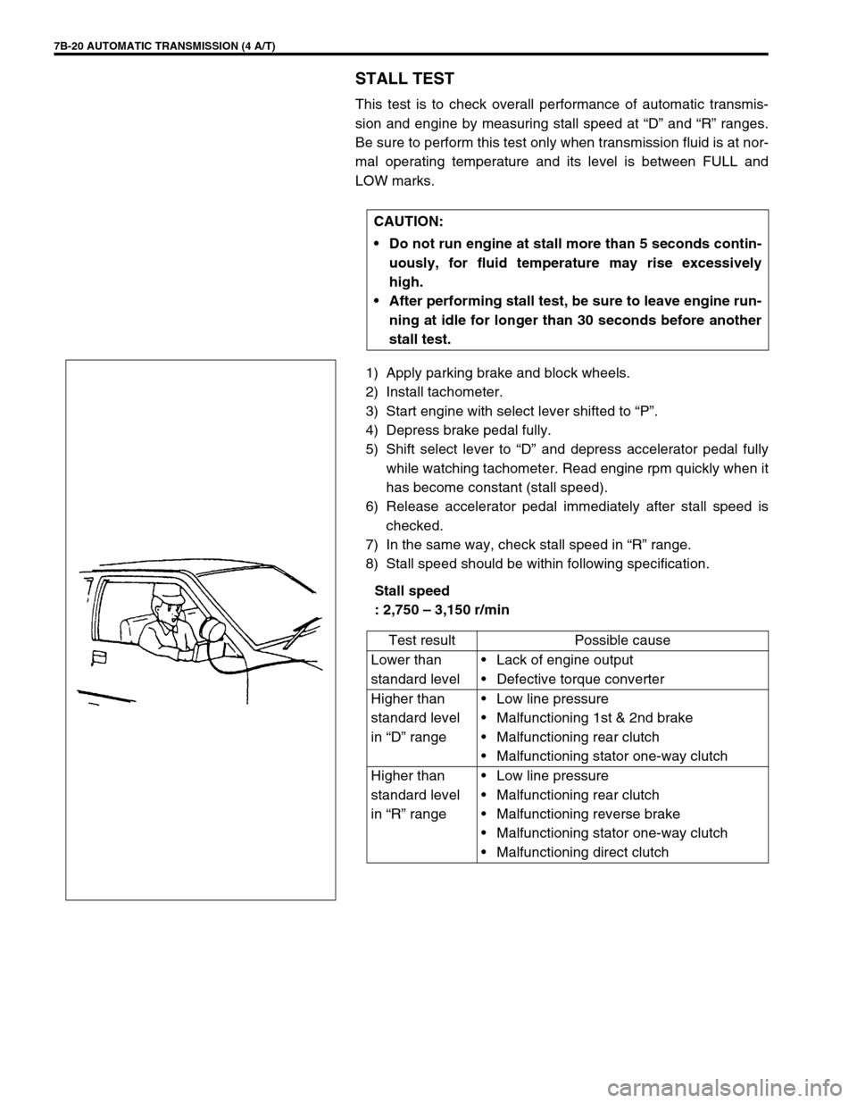
STALL TEST
This test is to check overall performance of automatic transmis-
sion and engine by measuring stall speed at “D” and “R” ranges.
Be sure to perform this test only when transmission fluid is at nor-
mal operating temperature and its level is between FULL and
LOW marks.
1) Apply parking brake and block wheels.
2) Install tachometer.
3) Start engine with select lever shifted to “P”.
4) Depress brake pedal fully.
5) Shift select lever to “D” and depress accelerator pedal fully
while watching tachometer. Read engine rpm quickly when it
has become constant (stall speed).
6) Release accelerator pedal immediately after stall speed is
checked.
7) In the same way, check stall speed in “R” range.
8) Stall speed should be within following specification.
Stall speed
: 2,750 – 3,150 r/min CAUTION:
Do not run engine at stall more than 5 seconds contin-
uously, for fluid temperature may rise excessively
high.
After performing stall test, be sure to leave engine run-
ning at idle for longer than 30 seconds before another
stall test.
Test result Possible cause
Lower than
standard levelLack of engine output
Defective torque converter
Higher than
standard level
in “D” rangeLow line pressure
Malfunctioning 1st & 2nd brake
Malfunctioning rear clutch
Malfunctioning stator one-way clutch
Higher than
standard level
in “R” rangeLow line pressure
Malfunctioning rear clutch
Malfunctioning reverse brake
Malfunctioning stator one-way clutch
Malfunctioning direct clutch
Page 63 of 447
AUTOMATIC TRANSMISSION (4 A/T) 7B-21
TIME LAG TEST
This test is to check conditions of clutch, reverse brake and fluid
pressure. “Time lag” means time elapsed since select lever is
shifted with engine idling till shock is felt.
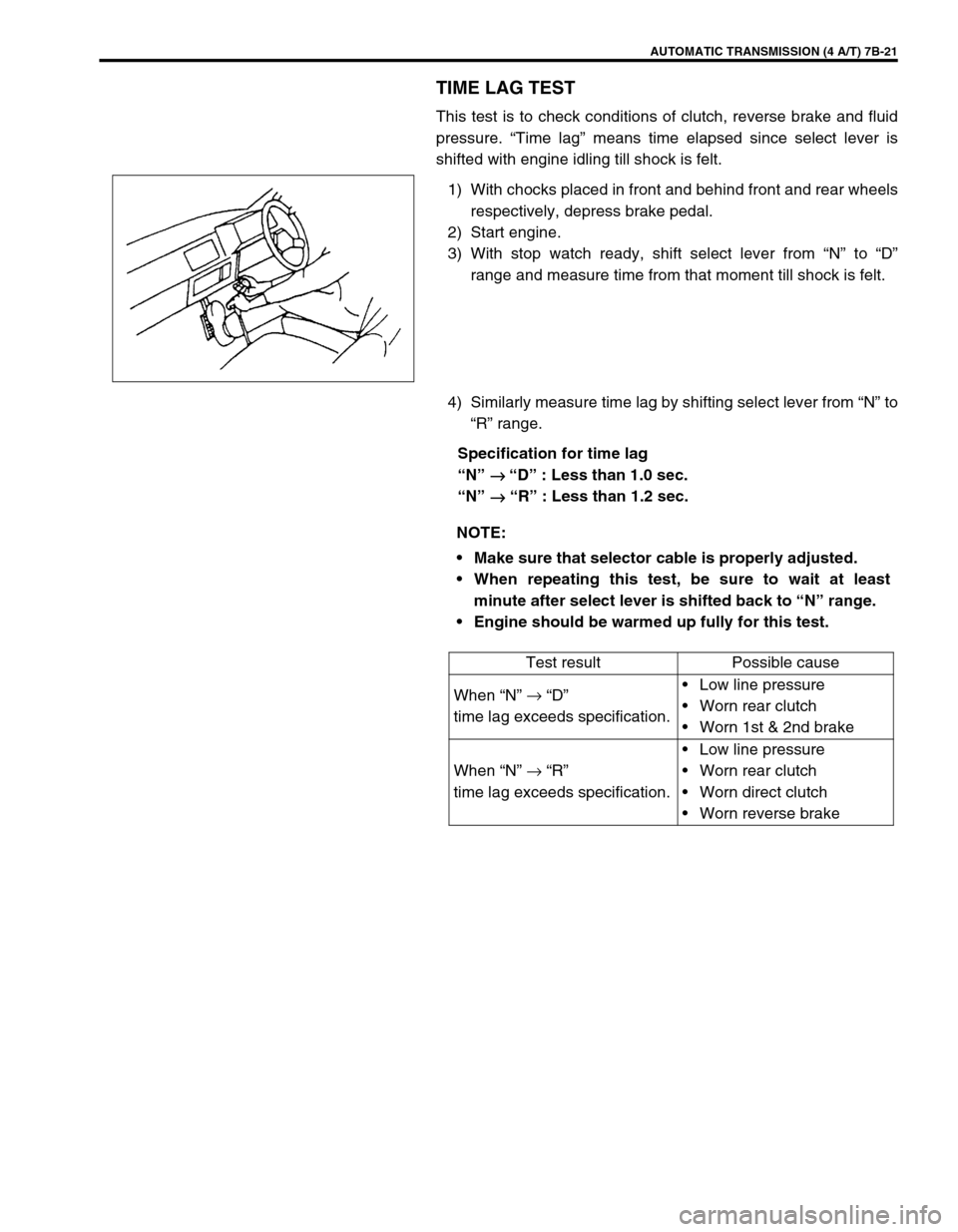
1) With chocks placed in front and behind front and rear wheels
respectively, depress brake pedal.
2) Start engine.
3) With stop watch ready, shift select lever from “N” to “D”
range and measure time from that moment till shock is felt.
4) Similarly measure time lag by shifting select lever from “N” to
“R” range.
Specification for time lag
“N”
→
→ → → “D” : Less than 1.0 sec.
“N”
→
→→ → “R” : Less than 1.2 sec.
NOTE:
Make sure that selector cable is properly adjusted.
When repeating this test, be sure to wait at least
minute after select lever is shifted back to “N” range.
Engine should be warmed up fully for this test.
Test result Possible cause
When “N” →
“D”
time lag exceeds specification.Low line pressure
Worn rear clutch
Worn 1st & 2nd brake
When “N” →
“R”
time lag exceeds specification.Low line pressure
Worn rear clutch
Worn direct clutch
Worn reverse brake
Page 64 of 447
7B-22 AUTOMATIC TRANSMISSION (4 A/T)
LINE PRESSURE TEST
Purpose of this test is to check operating conditions of each part
by measuring fluid pressure in fluid pressure line.
Line pressure test requires following conditions.
Automatic fluid is at normal operating temperature (70 –
80°C /158 – 176°F).
Fluid is filled to proper level (between FULL and LOW on
dipstick).
1) Apply parking brake securely and place chocks against
wheels.
2) Remove fluid pressure check hole plug bolt.
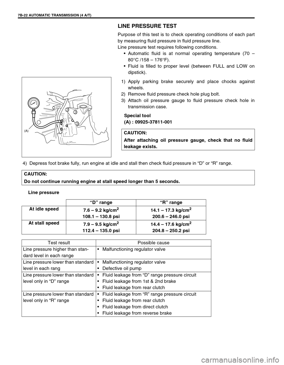
3) Attach oil pressure gauge to fluid pressure check hole in
transmission case.
Special tool
(A) : 09925-37811-001
4) Depress foot brake fully, run engine at idle and stall then check fluid pressure in “D” or “R” range.
Line pressureCAUTION:
After attaching oil pressure gauge, check that no fluid
leakage exists.
(A)
CAUTION:
Do not continue running engine at stall speed longer than 5 seconds.
“D” range “R” range
At idle speed
7.6 – 9.2 kg/cm
2
108.1 – 130.8 psi14.1 – 17.3 kg/cm
2
200.6 – 246.0 psi
At stall speed
7.9 – 9.5 kg/cm
2
112.4 – 135.0 psi14.4 – 17.6 kg/cm
2
204.8 – 250.2 psi
Test result Possible cause
Line pressure higher than stan-
dard level in each rangeMalfunctioning regulator valve
Line pressure lower than standard
level in each rangMalfunctioning regulator valve
Defective oil pump
Line pressure lower than standard
level only in “D” rangeFluid leakage from “D” range pressure circuit
Fluid leakage from 1st & 2nd brake
Fluid leakage from rear clutch
Line pressure lower than standard
level only in “R” rangeFluid leakage from “R” range pressure circuit
Fluid leakage from rear clutch
Fluid leakage from direct clutch
Fluid leakage from reverse brake
Page 65 of 447
AUTOMATIC TRANSMISSION (4 A/T) 7B-23
ENGINE BRAKE TEST
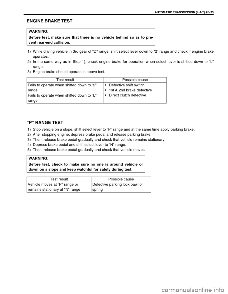
1) While driving vehicle in 3rd gear of “D” range, shift select lever down to “2” range and check if engine brake
operates.
2) In the same way as in Step 1), check engine brake for operation when select lever is shifted down to “L”
range.
3) Engine brake should operate in above test.
“P” RANGE TEST
1) Stop vehicle on a slope, shift select lever to “P” range and at the same time apply parking brake.
2) After stopping engine, depress brake pedal and release parking brake.
3) Then, release brake pedal gradually and check that vehicle remains stationary.
4) Depress brake pedal and shift select lever to “N” range.
5) Then, release brake pedal gradually and check that vehicle moves.WARNING:
Before test, make sure that there is no vehicle behind so as to pre-
vent rear-end collision.
Test result Possible cause
Fails to operate when shifted down to “2”
rangeDefective shift switch
1st & 2nd brake defective
Direct clutch defective
Fails to operate when shifted down to “L”
range
WARNING:
Before test, check to make sure no one is around vehicle or
down on a slope and keep watchful for safety during test.
Test result Possible cause
Vehicle moves at “P” range or
remains stationary at “N” rangeDefective parking lock pawl or
spring
Page 70 of 447

7B-28 AUTOMATIC TRANSMISSION (4 A/T)
DTC TABLE
DTC NO.
“O/D OFF” Lamp
Flashing Pattern of DTC
(Not using scan tool)DETECTING ITEMSMIL
Using
scan toolNot using
scan toolVehicle
equipped
with
immobi-
lizer indi-
cator lampVehicle
equipped
without
immobi-
lizer indi-
cator lamp
–12 Normal––
P0715 14Input/Turbine speed sensor circuit
malfunction1 driving
cycleNot
applicable
P0730 18 Incorrect gear ratio2 driving
cyclesNot
applicable
P075321
Shift solenoid-A (No.1) electrical1 driving
cycleNot
applicable
22
P075823
Shift solenoid-B (No.2) electrical1 driving
cycleNot
applicable
24
P0763 43 Shift solenoid-C (No.3) electrical1 driving
cycleNot
applicable
P0768 45 Shift solenoid-D (No.4) electrical1 driving
cycleNot
applicable
P0773 48 Shift solenoid-E (No.5) electrical1 driving
cycleNot
applicable
P074325
Torque converter clutch (lock-up)
system electrical1 driving
cycleNot
applicable
26
Page 71 of 447
AUTOMATIC TRANSMISSION (4 A/T) 7B-29
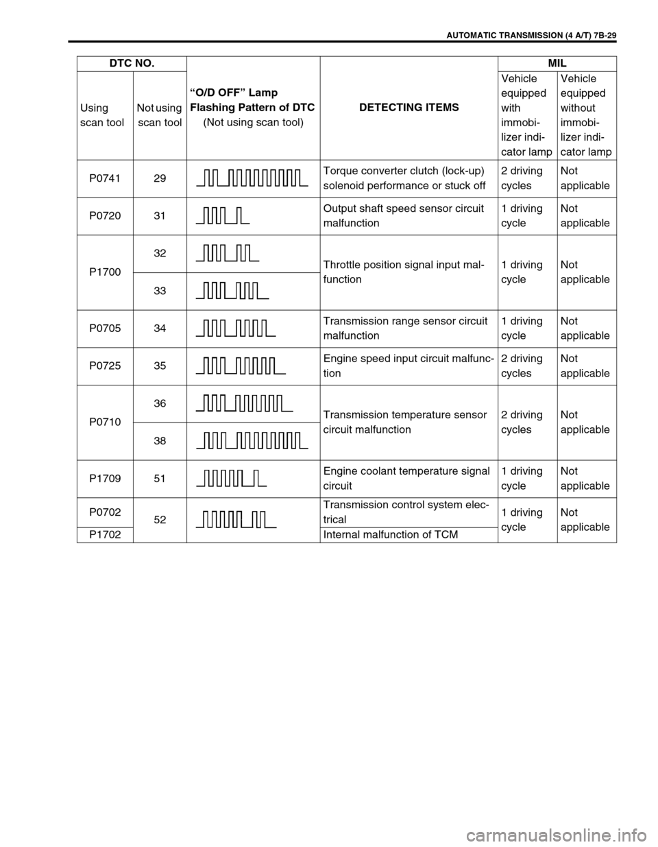
P0741 29Torque converter clutch (lock-up)
solenoid performance or stuck off2 driving
cyclesNot
applicable
P0720 31Output shaft speed sensor circuit
malfunction1 driving
cycleNot
applicable
P170032
Throttle position signal input mal-
function1 driving
cycleNot
applicable
33
P0705 34Transmission range sensor circuit
malfunction1 driving
cycleNot
applicable
P0725 35Engine speed input circuit malfunc-
tion2 driving
cyclesNot
applicable
P071036
Transmission temperature sensor
circuit malfunction2 driving
cyclesNot
applicable
38
P1709 51Engine coolant temperature signal
circuit1 driving
cycleNot
applicable
P0702
52Transmission control system elec-
trical1 driving
cycleNot
applicable
P1702 Internal malfunction of TCMDTC NO.
“O/D OFF” Lamp
Flashing Pattern of DTC
(Not using scan tool)DETECTING ITEMSMIL
Using
scan toolNot using
scan toolVehicle
equipped
with
immobi-
lizer indi-
cator lampVehicle
equipped
without
immobi-
lizer indi-
cator lamp