brake SUZUKI SWIFT 2000 1.G Transmission Service Owner's Guide
[x] Cancel search | Manufacturer: SUZUKI, Model Year: 2000, Model line: SWIFT, Model: SUZUKI SWIFT 2000 1.GPages: 447, PDF Size: 10.54 MB
Page 163 of 447

AUTOMATIC TRANSMISSION (4 A/T) 7B-121
12) Measure 1st & 2nd brake (B1) stroke and clearance in fol-
lowing manner.
Set the dial gauge (1) to 1st & 2nd brake (B1) piston as
shown. Blow compressed air into hole (4) shown in figure.
Then measure the difference as the compressed air is blown
in.
1st & 2nd brake (B1) piston stroke
Standard : 1.79 – 2.01 mm (0.0705 – 0.0791 in.)
Set the dial gauge (1) on the top-most brake disc (5).
Blow compressed air into the hole (4) shown in figure.
Measure the difference. Call this value (A).
If the measured value (s) is (are) out of specification, replace
brake discs, plates and flange.
1st & 2nd brake (B1) disc clearance
Standard : 1.31 – 1.96 mm (0.0516 – 0.0772 in.)
\
13) Install O/D brake (B0) return spring seat (4), return spring (3)
and then retainer (2).
14) While compressing retainer (2), install snap ring (1).
2. Tip of dial gauge on B1 brake piston
3. Air gun
CAUTION:
Position return spring (3) to be centered so that rear
cover not be caught.
Page 164 of 447

7B-122 AUTOMATIC TRANSMISSION (4 A/T)
15) Install thrust needle roller bearing (1) and planetary sun gear
No.2 (2). Turn planetary sun gear No.2 (2) right and left to
match the brake discs and the spline of planetary sun gear
No.2.
16) Install thrust needle roller bearing (3) and planetary set (4).
Turn planetary set (4) right and left to match the gears of the
planetary sun gear No.2 (2) and the gears of the planetary
set (4).
17) Install thrust needle roller bearing (5) and planetary sun gear
No.1 assembly (6). Turn planetary sun gear No.1 assembly
(6) right and left to match the gears of planetary set (4) and
the gears of planetary sun gear No.1 assembly (6).
18) Install O/D brake (B0) discs (1) and plates (2).
Page 165 of 447

AUTOMATIC TRANSMISSION (4 A/T) 7B-123
19) Measure the clearance of O/D brake (B0) in the following
manner.
Blow compressed air into hole (4) shown in figure to activate
1st & 2nd brake (B1) piston, then measure the distance
between the top of O/D brake (B0) plate and the transmis-
sion case – rear cover mating surface.
Call this value (A).
((A) = The value on vernier caliper – width of straight edge )
Measure the distance from top of O/D brake (B0) piston (on
rear cover) to rear cover – transmission case mating surface.
Call this value (B).
Clearance = (A) – (B) + 0.4
O/D brake (B0) clearance
Standard : 0.80 – 1.40 mm (0.0315 – 0.0551 in.)
20) If the obtained value is out of standard value, replace brake
disc and plate.
21) Install O/D brake piston adapter (1) thrust needle roller bear-
ing (2) and direct clutch (C0) assembly (3).
1. Straight edge
2. Vernier caliper
3. Rear cover assembly (with B0 piston)
5. Air gun
6. O/D brake piston adapter
Page 168 of 447

7B-126 AUTOMATIC TRANSMISSION (4 A/T)
32) Install parking lock pawl (2).
33) Install parking lock pawl shaft (4), torsional spring (3), and
cover (1), then hold them with 2 bolts.
Tightening torque
Parking lock pawl bolts (a) : 11 N·m (1.1 kg-m, 8.0 lb-ft)
34) Install reverse brake (B2) plates, discs, flange and cushion
plate in following order :
(1) Cushion plate →
(2) Plate →
(3) Disc →
(4) Plate →
(5)
Disc →
(6) Plate →
(7) Disc →
(8) Plate →
(9) Disc →
(10)
Flange
35) Hold above parts with snap ring.
NOTE:
Note the direction of cushion plate (1).
Make sure that the plates are fitted into groove of
transmission case as shown in figure.
2. Brake plate side
3. Transmission case side
Page 169 of 447
AUTOMATIC TRANSMISSION (4 A/T) 7B-127
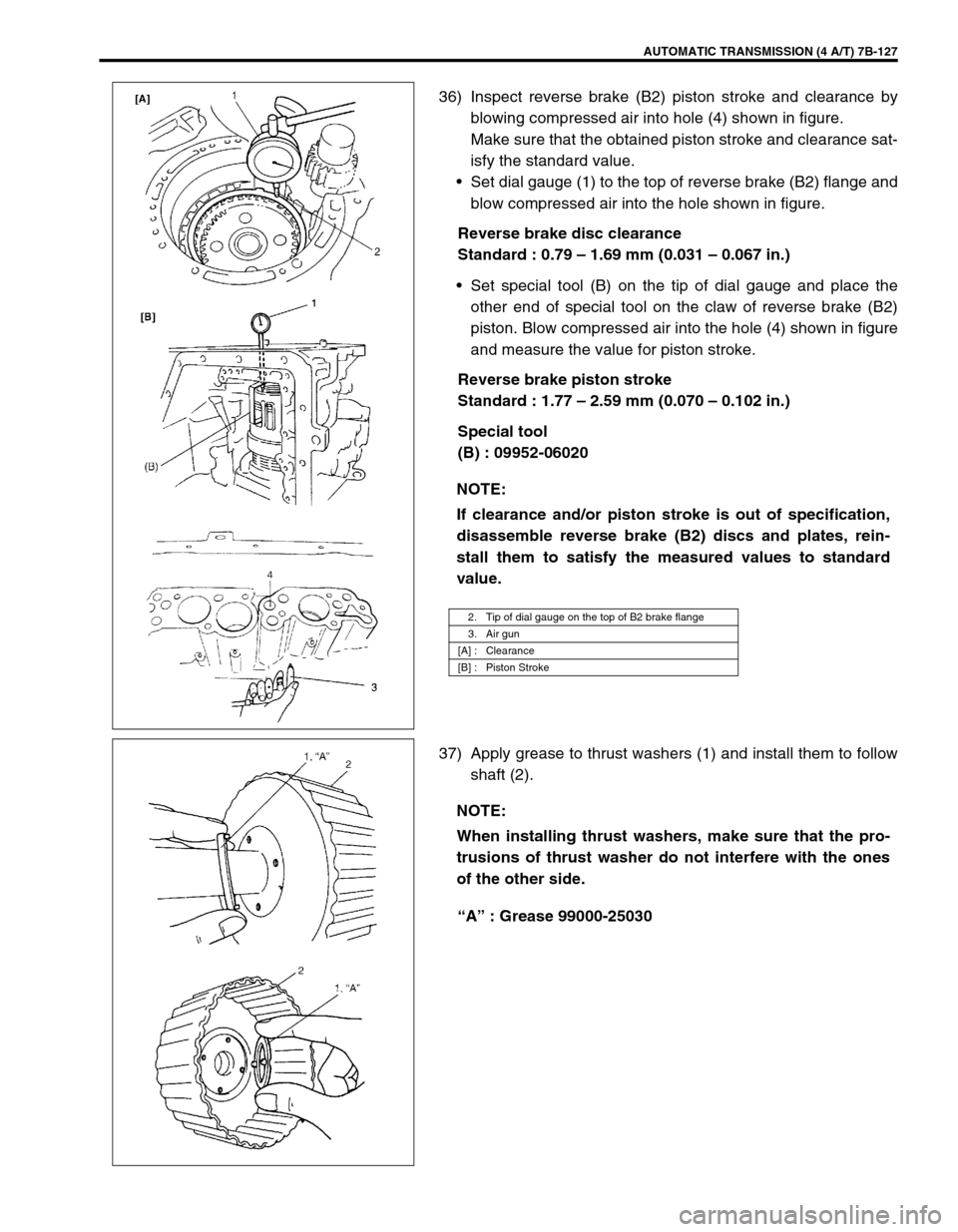
36) Inspect reverse brake (B2) piston stroke and clearance by
blowing compressed air into hole (4) shown in figure.
Make sure that the obtained piston stroke and clearance sat-
isfy the standard value.
Set dial gauge (1) to the top of reverse brake (B2) flange and
blow compressed air into the hole shown in figure.
Reverse brake disc clearance
Standard : 0.79 – 1.69 mm (0.031 – 0.067 in.)
Set special tool (B) on the tip of dial gauge and place the
other end of special tool on the claw of reverse brake (B2)
piston. Blow compressed air into the hole (4) shown in figure
and measure the value for piston stroke.
Reverse brake piston stroke
Standard : 1.77 – 2.59 mm (0.070 – 0.102 in.)
Special tool
(B) : 09952-06020
37) Apply grease to thrust washers (1) and install them to follow
shaft (2).
“A” : Grease 99000-25030 NOTE:
If clearance and/or piston stroke is out of specification,
disassemble reverse brake (B2) discs and plates, rein-
stall them to satisfy the measured values to standard
value.
2. Tip of dial gauge on the top of B2 brake flange
3. Air gun
[A] : Clearance
[B] : Piston Stroke
NOTE:
When installing thrust washers, make sure that the pro-
trusions of thrust washer do not interfere with the ones
of the other side.
Page 170 of 447

7B-128 AUTOMATIC TRANSMISSION (4 A/T)
38) Install follow shaft (1) to transmission case.
Turn it right and left to match the reverse brake (B2) discs
and the spline of follow shaft.
39) Install thrust needle roller bearing (1) to intermediate shaft
(2).
40) Install intermediate shaft (1) to transmission case.
41) Install rear clutch assembly (1) by turning it right and left to
match the clutch disc of rear clutch assembly and the spline
of intermediate shaft.
42) Install thrust bearing race (2).
“A” : Grease 99000-25030
43) Install front clutch assembly (1) by turning it right and left to
match the clutch of disc clutch assembly and the spline of
follow shaft. NOTE:
When installing follow shaft, do not let the thrust washer
fall off from follow shaft.
Page 189 of 447
CLUTCH 7C-7
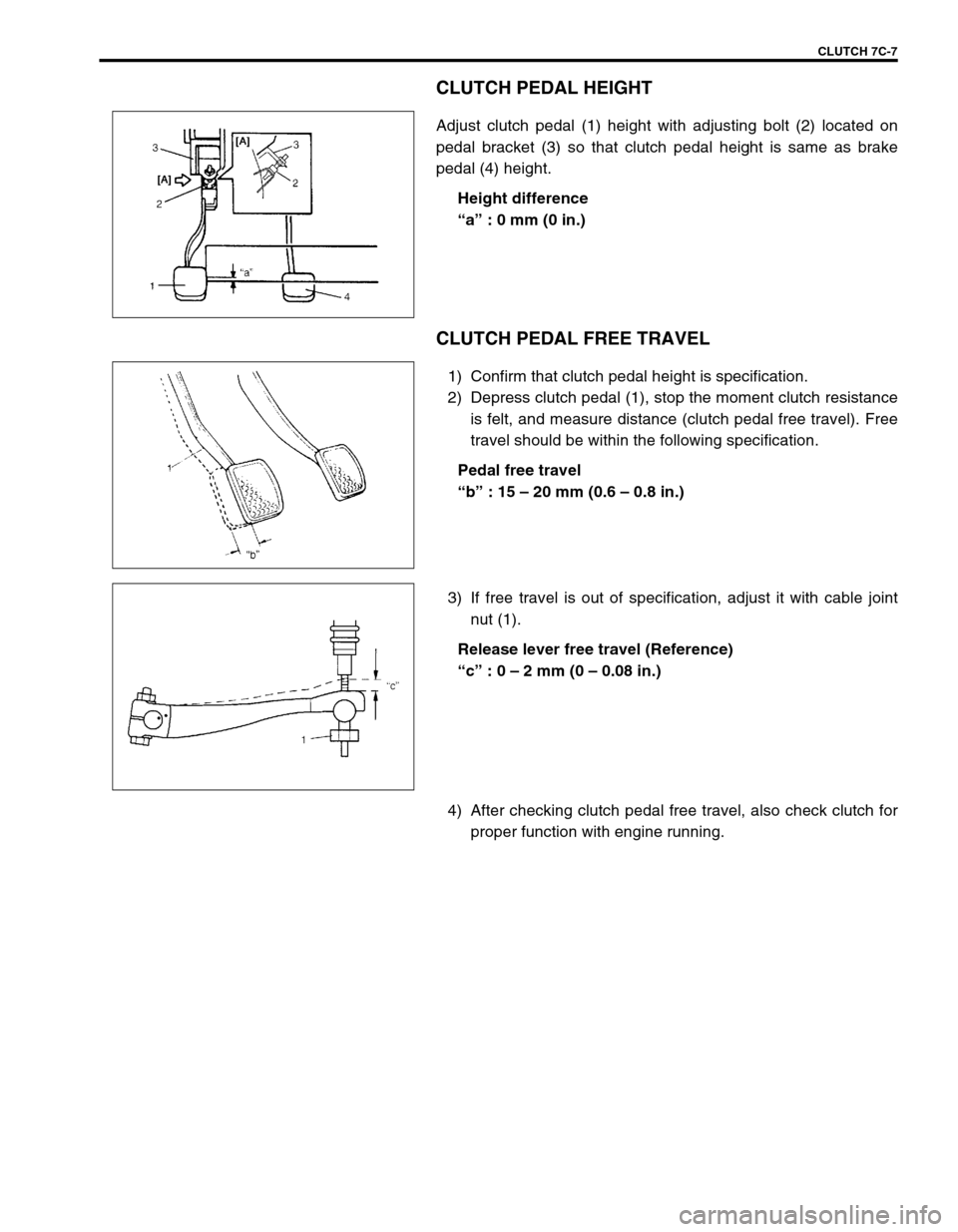
CLUTCH PEDAL HEIGHT
Adjust clutch pedal (1) height with adjusting bolt (2) located on
pedal bracket (3) so that clutch pedal height is same as brake
pedal (4) height.
Height difference
“a” : 0 mm (0 in.)
CLUTCH PEDAL FREE TRAVEL
1) Confirm that clutch pedal height is specification.
2) Depress clutch pedal (1), stop the moment clutch resistance
is felt, and measure distance (clutch pedal free travel). Free
travel should be within the following specification.
Pedal free travel
“b” : 15 – 20 mm (0.6 – 0.8 in.)
3) If free travel is out of specification, adjust it with cable joint
nut (1).
Release lever free travel (Reference)
“c” : 0 – 2 mm (0 – 0.08 in.)
4) After checking clutch pedal free travel, also check clutch for
proper function with engine running.
Page 228 of 447
7F-6 REAR DIFFERENTIAL
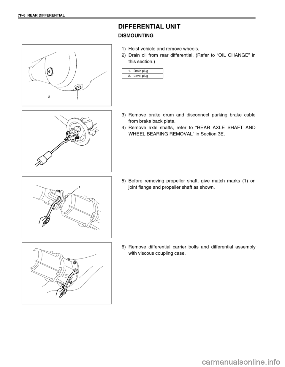
DIFFERENTIAL UNIT
DISMOUNTING
1) Hoist vehicle and remove wheels.
2) Drain oil from rear differential. (Refer to “OIL CHANGE” in
this section.)
3) Remove brake drum and disconnect parking brake cable
from brake back plate.
4) Remove axle shafts, refer to “REAR AXLE SHAFT AND
WHEEL BEARING REMOVAL” in Section 3E.
5) Before removing propeller shaft, give match marks (1) on
joint flange and propeller shaft as shown.
6) Remove differential carrier bolts and differential assembly
with viscous coupling case.
1. Drain plug
2. Level plug
1
Page 229 of 447
REAR DIFFERENTIAL 7F-7
REMOUNTING
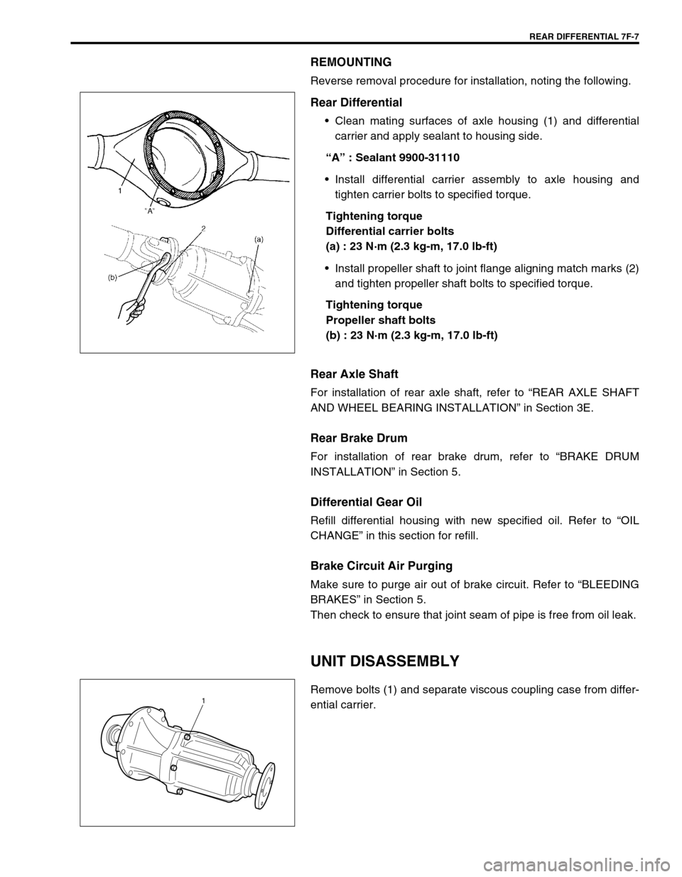
Reverse removal procedure for installation, noting the following.
Rear Differential
Clean mating surfaces of axle housing (1) and differential
carrier and apply sealant to housing side.
“A” : Sealant 9900-31110
Install differential carrier assembly to axle housing and
tighten carrier bolts to specified torque.
Tightening torque
Differential carrier bolts
(a) : 23 N·m (2.3 kg-m, 17.0 lb-ft)
Install propeller shaft to joint flange aligning match marks (2)
and tighten propeller shaft bolts to specified torque.
Tightening torque
Propeller shaft bolts
(b) : 23 N·m (2.3 kg-m, 17.0 lb-ft)
Rear Axle Shaft
For installation of rear axle shaft, refer to “REAR AXLE SHAFT
AND WHEEL BEARING INSTALLATION” in Section 3E.
Rear Brake Drum
For installation of rear brake drum, refer to “BRAKE DRUM
INSTALLATION” in Section 5.
Differential Gear Oil
Refill differential housing with new specified oil. Refer to “OIL
CHANGE” in this section for refill.
Brake Circuit Air Purging
Make sure to purge air out of brake circuit. Refer to “BLEEDING
BRAKES” in Section 5.
Then check to ensure that joint seam of pipe is free from oil leak.
UNIT DISASSEMBLY
Remove bolts (1) and separate viscous coupling case from differ-
ential carrier.1
Page 245 of 447
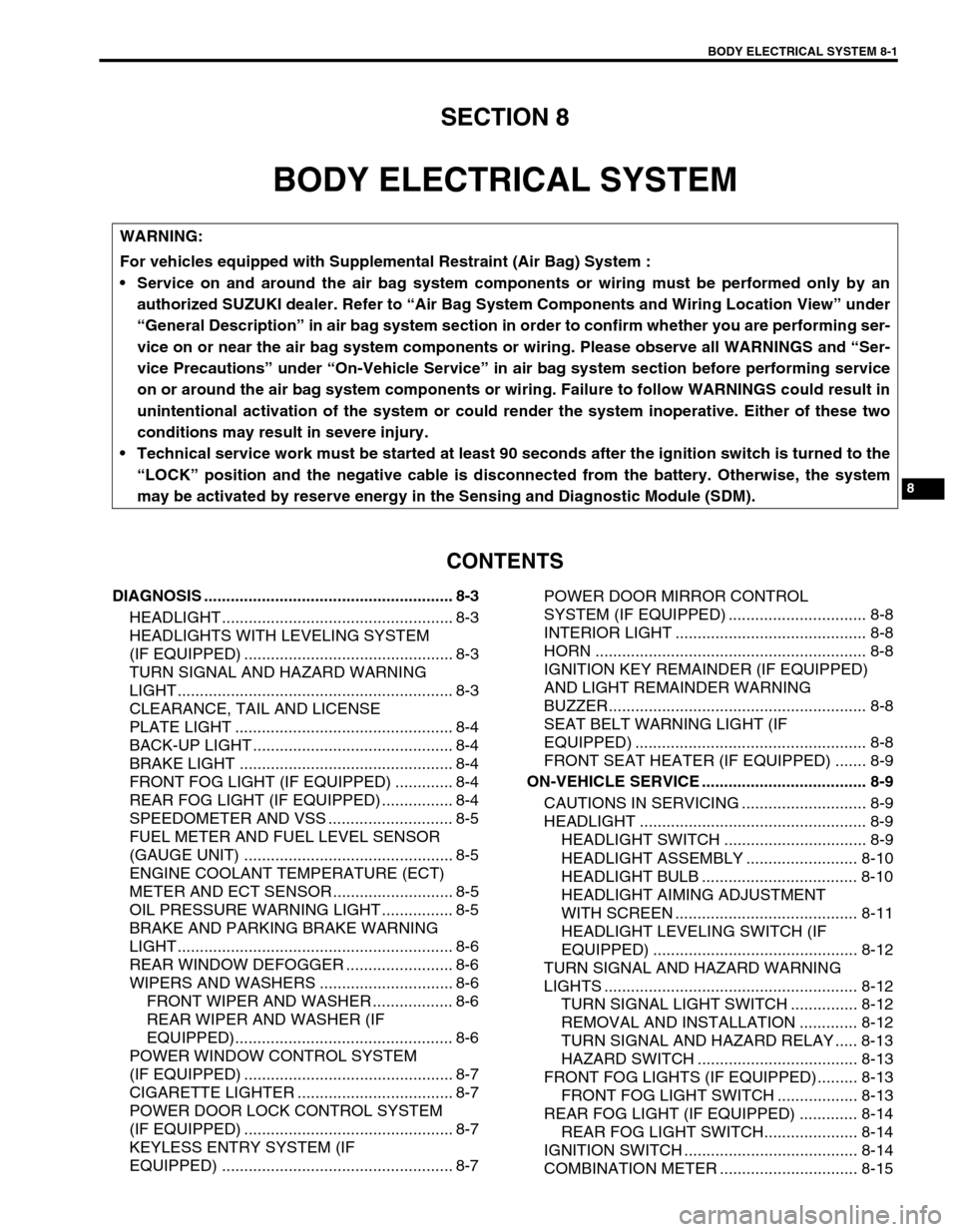
BODY ELECTRICAL SYSTEM 8-1
6F1
6F2
6G
6H
6K
7A
7A1
7B1
7C1
7D
7E
7F
8A
8
8D
8E
9
10
10A
10B
SECTION 8
BODY ELECTRICAL SYSTEM
CONTENTS
DIAGNOSIS ........................................................ 8-3
HEADLIGHT .................................................... 8-3
HEADLIGHTS WITH LEVELING SYSTEM
(IF EQUIPPED) ............................................... 8-3
TURN SIGNAL AND HAZARD WARNING
LIGHT .............................................................. 8-3
CLEARANCE, TAIL AND LICENSE
PLATE LIGHT ................................................. 8-4
BACK-UP LIGHT ............................................. 8-4
BRAKE LIGHT ................................................ 8-4
FRONT FOG LIGHT (IF EQUIPPED) ............. 8-4
REAR FOG LIGHT (IF EQUIPPED) ................ 8-4
SPEEDOMETER AND VSS ............................ 8-5
FUEL METER AND FUEL LEVEL SENSOR
(GAUGE UNIT) ............................................... 8-5
ENGINE COOLANT TEMPERATURE (ECT)
METER AND ECT SENSOR ........................... 8-5
OIL PRESSURE WARNING LIGHT ................ 8-5
BRAKE AND PARKING BRAKE WARNING
LIGHT .............................................................. 8-6
REAR WINDOW DEFOGGER ........................ 8-6
WIPERS AND WASHERS .............................. 8-6
FRONT WIPER AND WASHER .................. 8-6
REAR WIPER AND WASHER (IF
EQUIPPED)................................................. 8-6
POWER WINDOW CONTROL SYSTEM
(IF EQUIPPED) ............................................... 8-7
CIGARETTE LIGHTER ................................... 8-7
POWER DOOR LOCK CONTROL SYSTEM
(IF EQUIPPED) ............................................... 8-7
KEYLESS ENTRY SYSTEM (IF
EQUIPPED) .................................................... 8-7POWER DOOR MIRROR CONTROL
SYSTEM (IF EQUIPPED) ............................... 8-8
INTERIOR LIGHT ........................................... 8-8
HORN ............................................................. 8-8
IGNITION KEY REMAINDER (IF EQUIPPED)
AND LIGHT REMAINDER WARNING
BUZZER.......................................................... 8-8
SEAT BELT WARNING LIGHT (IF
EQUIPPED) .................................................... 8-8
FRONT SEAT HEATER (IF EQUIPPED) ....... 8-9
ON-VEHICLE SERVICE ..................................... 8-9
CAUTIONS IN SERVICING ............................ 8-9
HEADLIGHT ................................................... 8-9
HEADLIGHT SWITCH ................................ 8-9
HEADLIGHT ASSEMBLY ......................... 8-10
HEADLIGHT BULB ................................... 8-10
HEADLIGHT AIMING ADJUSTMENT
WITH SCREEN ......................................... 8-11
HEADLIGHT LEVELING SWITCH (IF
EQUIPPED) .............................................. 8-12
TURN SIGNAL AND HAZARD WARNING
LIGHTS ......................................................... 8-12
TURN SIGNAL LIGHT SWITCH ............... 8-12
REMOVAL AND INSTALLATION ............. 8-12
TURN SIGNAL AND HAZARD RELAY ..... 8-13
HAZARD SWITCH .................................... 8-13
FRONT FOG LIGHTS (IF EQUIPPED)......... 8-13
FRONT FOG LIGHT SWITCH .................. 8-13
REAR FOG LIGHT (IF EQUIPPED) ............. 8-14
REAR FOG LIGHT SWITCH..................... 8-14
IGNITION SWITCH ....................................... 8-14
COMBINATION METER ............................... 8-15 WARNING:
For vehicles equipped with Supplemental Restraint (Air Bag) System :
Service on and around the air bag system components or wiring must be performed only by an
authorized SUZUKI dealer. Refer to “Air Bag System Components and Wiring Location View” under
“General Description” in air bag system section in order to confirm whether you are performing ser-
vice on or near the air bag system components or wiring. Please observe all WARNINGS and “Ser-
vice Precautions” under “On-Vehicle Service” in air bag system section before performing service
on or around the air bag system components or wiring. Failure to follow WARNINGS could result in
unintentional activation of the system or could render the system inoperative. Either of these two
conditions may result in severe injury.
Technical service work must be started at least 90 seconds after the ignition switch is turned to the
“LOCK” position and the negative cable is disconnected from the battery. Otherwise, the system
may be activated by reserve energy in the Sensing and Diagnostic Module (SDM).