brake SUZUKI SWIFT 2000 1.G Transmission Service Service Manual
[x] Cancel search | Manufacturer: SUZUKI, Model Year: 2000, Model line: SWIFT, Model: SUZUKI SWIFT 2000 1.GPages: 447, PDF Size: 10.54 MB
Page 246 of 447
8-2 BODY ELECTRICAL SYSTEM
CIRCUIT.................................................... 8-15
FUEL METER AND FUEL LEVEL
SENSOR (GAUGE UNIT) ............................. 8-16
FUEL LEVEL METER ............................... 8-16
FUEL LEVEL SENSOR (GAUGE UNIT) ... 8-17
SPEED METER AND VSS ........................... 8-17
VSS ........................................................... 8-17
ENGINE COOLANT TEMPERATURE (ECT)
METER AND SENSOR................................. 8-17
ENGINE COOLANT TEMPERATURE
(ECT) METER ........................................... 8-17
ECT SENSOR ........................................... 8-18
OIL PRESSURE WARNING LIGHT ............. 8-18
OIL PRESSURE SWITCH ........................ 8-18
BRAKE FLUID LEVEL AND PARKING
BRAKE WARNING LIGHT ............................ 8-18
BRAKE FLUID LEVEL SWITCH ............... 8-18
PARKING BRAKE SWITCH...................... 8-19
REAR WINDOW DEFOGGER...................... 8-19
DEFOGGER SWITCH .............................. 8-19
DEFOGGER WIRE ................................... 8-19
WIPERS AND WASHERS ............................ 8-21
COMPONENTS ........................................ 8-21
FRONT WIPER AND WASHER
SWITCH .................................................... 8-21
FRONT WIPER MOTOR........................... 8-23
WASHER TANK AND WASHER
PUMP ........................................................ 8-24
REAR WIPER AND WASHER SWITCH
(IF EQUIPPED) ......................................... 8-25REAR WIPER MOTOR .............................. 8-25
IGNITION KEY REMAINDER (IF EQUIPPED)
AND LIGHT REMAINDER WARNING
BUZZER ........................................................ 8-25
POWER WINDOW CONTROL SYSTEM
(IF EQUIPPED).............................................. 8-26
POWER WINDOW MAIN SWITCH ........... 8-26
POWER WINDOW SUB SWITCH ............. 8-27
DOOR SWITCH ............................................. 8-27
STOP LAMP (BRAKE) SWITCH ................... 8-27
POWER DOOR LOCK SYSTEM (IF
EQUIPPED) ................................................... 8-28
DOOR LOCK CONTROLLER .................... 8-28
DRIVER’S DOOR KNOB SWITCH ............ 8-28
DOOR LOCK ACTUATOR......................... 8-29
KEYLESS ENTRY SYSTEM (IF
EQUIPPED) ................................................... 8-29
DOOR LOCK CONTROLLER .................... 8-29
DOOR LOCK ACTUATOR......................... 8-29
RECEIVER................................................. 8-30
TRANSMITTER ......................................... 8-30
POWER DOOR MIRROR CONTROL
SYSTEM (IF EQUIPPED) .............................. 8-31
MIRROR SWITCH ..................................... 8-31
DOOR MIRROR ACTUATOR .................... 8-32
FRONT SEAT HEATER (IF EQUIPPED) ...... 8-32
SEAT HEATER SWITCH (DRIVER AND
PASSENGER SIDE) .................................. 8-32
SEAT HEATER WIRE................................ 8-33
Page 248 of 447
8-4 BODY ELECTRICAL SYSTEM
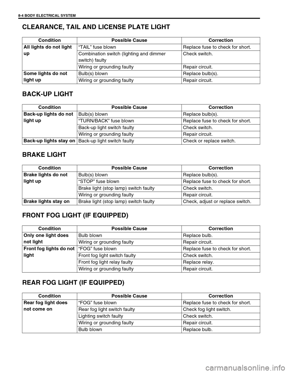
CLEARANCE, TAIL AND LICENSE PLATE LIGHT
BACK-UP LIGHT
BRAKE LIGHT
FRONT FOG LIGHT (IF EQUIPPED)
REAR FOG LIGHT (IF EQUIPPED)
Condition Possible Cause Correction
All lights do not light
up“TAlL” fuse blown Replace fuse to check for short.
Combination switch (lighting and dimmer
switch) faultyCheck switch.
Wiring or grounding faulty Repair circuit.
Some lights do not
light upBulb(s) blown Replace bulb(s).
Wiring or grounding faulty Repair circuit.
Condition Possible Cause Correction
Back-up lights do not
light upBulb(s) blown Replace bulb(s).
“TURN/BACK” fuse blown Replace fuse to check for short.
Back-up light switch faulty Check switch.
Wiring or grounding faulty Repair circuit.
Back-up lights stay on
Back-up light switch faulty Check or replace switch.
Condition Possible Cause Correction
Brake lights do not
light upBulb(s) blown Replace bulb(s).
“STOP” fuse blown Replace fuse to check for short.
Brake light (stop lamp) switch faulty Check switch.
Wiring or grounding faulty Repair circuit.
Brake lights stay on
Brake light (stop lamp) switch faulty Check, adjust or replace switch.
Condition Possible Cause Correction
Only one light does
not lightBulb blown Replace bulb.
Wiring or grounding faulty Repair circuit.
Front fog lights do not
light“FOG” fuse blown Replace fuse to check for short.
Front fog light switch faulty Check switch.
Front fog light relay faulty Replace relay.
Wiring or grounding faulty Repair circuit.
Condition Possible Cause Correction
Rear fog light does
not come on“FOG” fuse blown Replace fuse to check for short.
Rear fog light switch faulty Check fog light switch.
Lighting switch faulty Check switch.
Wiring or grounding faulty Repair circuit.
Bulb blown Replace bulb.
Page 250 of 447
8-6 BODY ELECTRICAL SYSTEM
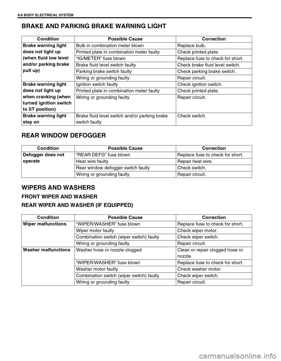
BRAKE AND PARKING BRAKE WARNING LIGHT
REAR WINDOW DEFOGGER
WIPERS AND WASHERS
FRONT WIPER AND WASHER
REAR WIPER AND WASHER (IF EQUIPPED)
Condition Possible Cause Correction
Brake warning light
does not light up
(when fluid low level
and/or parking brake
pull up)Bulb in combination meter blown Replace bulb.
Printed plate in combination meter faulty Check printed plate.
“IG/METER” fuse blown Replace fuse to check for short.
Brake fluid level switch faulty Check brake fluid level switch.
Parking brake switch faulty Check parking brake switch.
Wiring or grounding faulty Repair circuit.
Brake warning light
does not light up
when cranking (when
turned ignition switch
to ST position)Ignition switch faulty Check ignition switch.
Printed plate in combination meter faulty Check printed plate.
Wiring or grounding faulty Repair circuit.
Brake warning light
stay onBrake fluid level switch and/or parking brake
switch faultyCheck switch.
Condition Possible Cause Correction
Defogger does not
operate“REAR DEFG” fuse blown Replace fuse to check for short.
Heat wire faulty Repair heat wire.
Rear window defogger switch faulty Check switch.
Wiring or grounding faulty Repair circuit.
Condition Possible Cause Correction
Wiper malfunctions
“WIPER/WASHER” fuse blown Replace fuse to check for short.
Wiper motor faulty Check wiper motor.
Combination switch (wiper switch) faulty Check wiper switch.
Wiring or grounding faulty Repair circuit.
Washer malfunctions
Washer hose or nozzle clogged Clean or repair clogged hose or
nozzle.
“WIPER/WASHER” fuse blown Replace fuse to check for short.
Washer motor faulty Check washer motor.
Combination switch (wiper switch) faulty Check wiper switch.
Wiring or grounding faulty Repair circuit.
Page 259 of 447
BODY ELECTRICAL SYSTEM 8-15
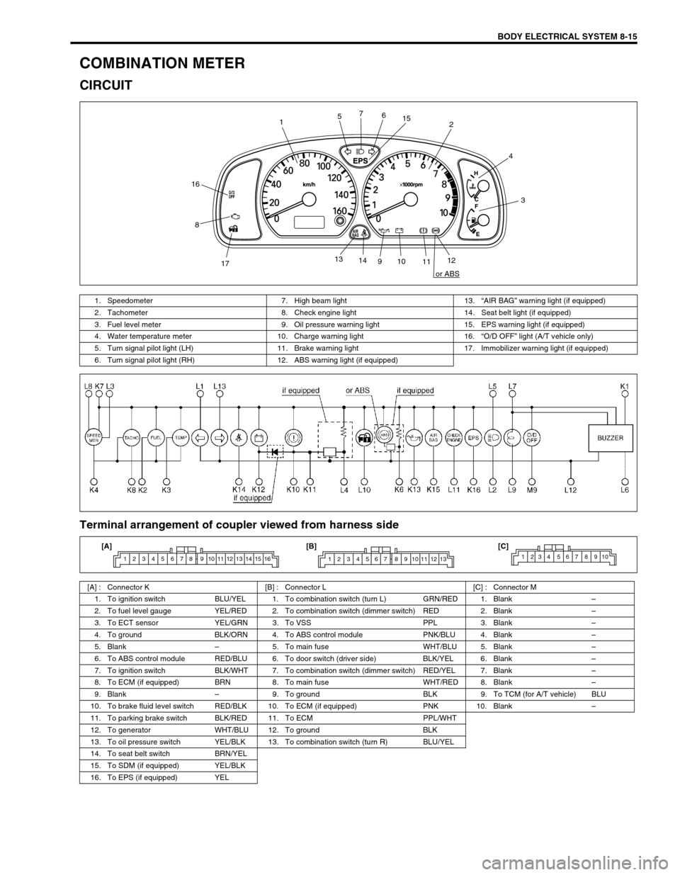
COMBINATION METER
CIRCUIT
Terminal arrangement of coupler viewed from harness side
12
3 4
56 7
8
910
1112 13
14
1715
16
or ABS
1. Speedometer 7. High beam light 13.“AIR BAG” warning light (if equipped)
2. Tachometer 8. Check engine light 14. Seat belt light (if equipped)
3. Fuel level meter 9. Oil pressure warning light 15. EPS warning light (if equipped)
4. Water temperature meter 10. Charge warning light 16.“O/D OFF” light (A/T vehicle only)
5. Turn signal pilot light (LH) 11. Brake warning light 17. Immobilizer warning light (if equipped)
6. Turn signal pilot light (RH) 12. ABS warning light (if equipped)
[A] : Connector K [B] : Connector L [C] : Connector M
1. To ignition switch BLU/YEL 1. To combination switch (turn L) GRN/RED 1. Blank–
2. To fuel level gauge YEL/RED 2. To combination switch (dimmer switch) RED 2. Blank–
3. To ECT sensor YEL/GRN 3. To VSS PPL 3. Blank–
4. To ground BLK/ORN 4. To ABS control module PNK/BLU 4. Blank–
5. Blank–5. To main fuse WHT/BLU 5. Blank–
6. To ABS control module RED/BLU 6. To door switch (driver side) BLK/YEL 6. Blank–
7. To ignition switch BLK/WHT 7. To combination switch (dimmer switch) RED/YEL 7. Blank–
8. To ECM (if equipped) BRN 8. To main fuse WHT/RED 8. Blank–
9. Blank–9. To ground BLK 9. To TCM (for A/T vehicle) BLU
10. To brake fluid level switch RED/BLK 10. To ECM (if equipped) PNK 10. Blank–
11. To parking brake switch BLK/RED 11. To ECM PPL/WHT
12. To generator WHT/BLU 12. To ground BLK
13. To oil pressure switch YEL/BLK 13. To combination switch (turn R) BLU/YEL
14. To seat belt switch BRN/YEL
15. To SDM (if equipped) YEL/BLK
16. To EPS (if equipped) YEL
1 2 3 4 5 6 7 8 9 10 11 12 13 14 15 161 2 3 4 5 6 7 8 9 10 11 12 131234 567 8910[A] [B] [C]
Page 262 of 447
8-18 BODY ELECTRICAL SYSTEM
ECT SENSOR
REMOVAL, INSTALLATION AND INSPECTION
Refer to “ECT SENSOR” in Section 6E1.
OIL PRESSURE WARNING LIGHT
OIL PRESSURE SWITCH
ON-VEHICLE INSPECTION
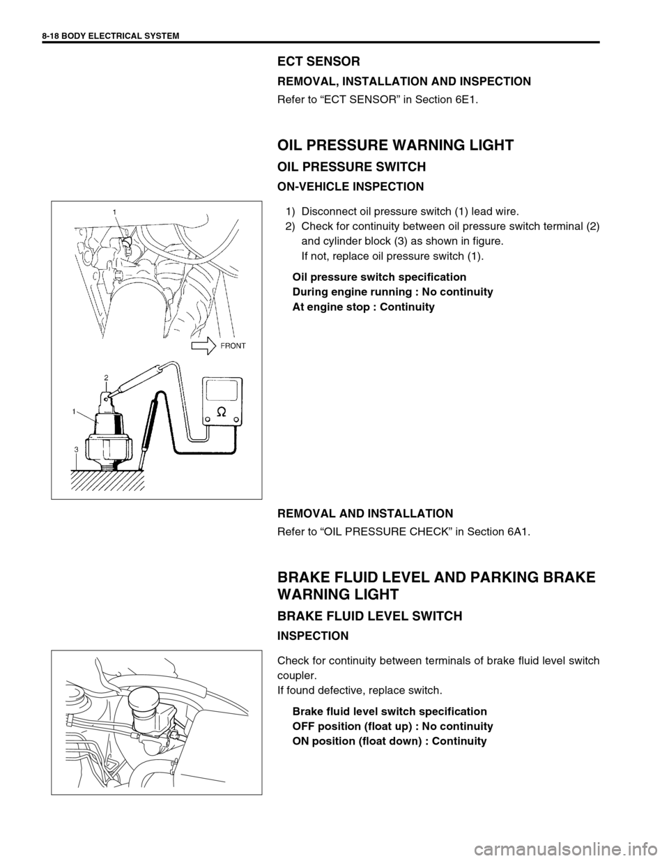
1) Disconnect oil pressure switch (1) lead wire.
2) Check for continuity between oil pressure switch terminal (2)
and cylinder block (3) as shown in figure.
If not, replace oil pressure switch (1).
Oil pressure switch specification
During engine running : No continuity
At engine stop : Continuity
REMOVAL AND INSTALLATION
Refer to “OIL PRESSURE CHECK” in Section 6A1.
BRAKE FLUID LEVEL AND PARKING BRAKE
WARNING LIGHT
BRAKE FLUID LEVEL SWITCH
INSPECTION
Check for continuity between terminals of brake fluid level switch
coupler.
If found defective, replace switch.
Brake fluid level switch specification
OFF position (float up) : No continuity
ON position (float down) : Continuity
Page 263 of 447
BODY ELECTRICAL SYSTEM 8-19
PARKING BRAKE SWITCH
INSPECTION
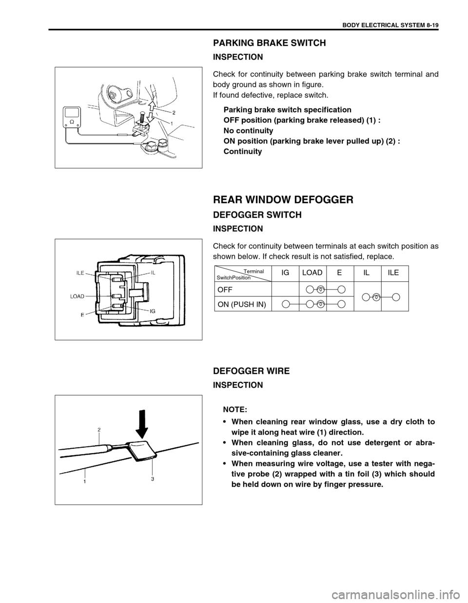
Check for continuity between parking brake switch terminal and
body ground as shown in figure.
If found defective, replace switch.
Parking brake switch specification
OFF position (parking brake released) (1) :
No continuity
ON position (parking brake lever pulled up) (2) :
Continuity
REAR WINDOW DEFOGGER
DEFOGGER SWITCH
INSPECTION
Check for continuity between terminals at each switch position as
shown below. If check result is not satisfied, replace.
DEFOGGER WIRE
INSPECTION
SwitchPositionTerminal
ON (PUSH IN)IG LOAD E IL ILE
OFF
NOTE:
When cleaning rear window glass, use a dry cloth to
wipe it along heat wire (1) direction.
When cleaning glass, do not use detergent or abra-
sive-containing glass cleaner.
When measuring wire voltage, use a tester with nega-
tive probe (2) wrapped with a tin foil (3) which should
be held down on wire by finger pressure.
Page 271 of 447
BODY ELECTRICAL SYSTEM 8-27
POWER WINDOW SUB SWITCH
INSPECTION
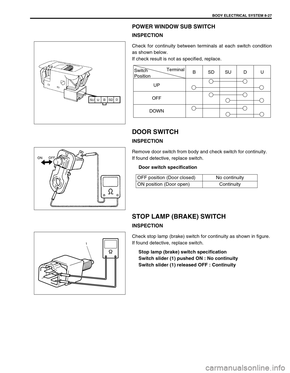
Check for continuity between terminals at each switch condition
as shown below.
If check result is not as specified, replace.
DOOR SWITCH
INSPECTION
Remove door switch from body and check switch for continuity.
If found detective, replace switch.
Door switch specification
STOP LAMP (BRAKE) SWITCH
INSPECTION
Check stop lamp (brake) switch for continuity as shown in figure.
If found detective, replace switch.
Stop lamp (brake) switch specification
Switch slider (1) pushed ON : No continuity
Switch slider (1) released OFF : Continuity
Terminal
Switch
Position
UPBSDSUD U
OFF
DOWN
OFF position (Door closed) No continuity
ON position (Door open) Continuity
1
Page 335 of 447
![SUZUKI SWIFT 2000 1.G Transmission Service Service Manual BODY SERVICE 9-31
SIDE BODY
Hole to hole distance
[A] : 3 door model f. Front shoulder adjuster installation upper hole
a. Door upper hinge installation hole g. Door switch installation hole
b. Door l SUZUKI SWIFT 2000 1.G Transmission Service Service Manual BODY SERVICE 9-31
SIDE BODY
Hole to hole distance
[A] : 3 door model f. Front shoulder adjuster installation upper hole
a. Door upper hinge installation hole g. Door switch installation hole
b. Door l](/img/20/7605/w960_7605-334.png)
BODY SERVICE 9-31
SIDE BODY
Hole to hole distance
[A] : 3 door model f. Front shoulder adjuster installation upper hole
a. Door upper hinge installation hole g. Door switch installation hole
b. Door lower hinge installation hole h. Side sill scuff installation hole
c. Front pillar inner trim installation lower hole i. Parking brake cable bracket installation rear hole
d. Front pillar inner trim installation upper hole
e. Assistant grip installation front hole
a-g : 1168 mm (45.98 in.) d-h : 1015 mm (39.96 in.) d-o : 1252 mm (49.29 in.)
a-h : 852 mm (33.54 in.) e-h : 1087 mm (42.80 in.) e-o : 1244 mm (48.98 in.)
b-g : 1188 mm (46.77 in.) f-h : 1091 mm (42.95 in.) f-o : 1173 mm (46.18 in.)
c-h : 924 mm (36.38 in.) a-o : 1317 mm (51.85 in.) g-o : 799 mm (31.46 in.)
d-f : 720 mm (28.35 in.) b-o : 1222 mm (48.11 in.) h-o : 816 mm (32.13 in.)
d-g : 933 mm (36.73 in.) c-o : 1283 mm (50.51 in.)
f
ge
d
c
a
b
h
f
ge
d
c
a
b
h o
o [A]
Page 336 of 447
![SUZUKI SWIFT 2000 1.G Transmission Service Service Manual 9-32 BODY SERVICE
Hole to hole distance
[B] : 5 door model f. Side sill scuff installation rear hole l. Rear door rear notch
a. Front door upper hinge installation hole g. Front shoulder adjuster inst SUZUKI SWIFT 2000 1.G Transmission Service Service Manual 9-32 BODY SERVICE
Hole to hole distance
[B] : 5 door model f. Side sill scuff installation rear hole l. Rear door rear notch
a. Front door upper hinge installation hole g. Front shoulder adjuster inst](/img/20/7605/w960_7605-335.png)
9-32 BODY SERVICE
Hole to hole distance
[B] : 5 door model f. Side sill scuff installation rear hole l. Rear door rear notch
a. Front door upper hinge installation hole g. Front shoulder adjuster installation upper
holem. Rear door switch installation hole
b. Front door lower hinge installation hole h. Rear door upper hinge installation hole n. Side soil scuff installation rear hole
c. Front pillar inner trim installation lower hole i. Front door switch installation hole o. Parking brake cable bracket installation rear
hole
d. Front pillar inner trim installation upper hole j. Rear door lower hinge installation hole p. Steering support member installation hole
e. Assistant grip installation front hole k. Assistant grip installation hole
a-g : 1166 mm (45.90 in.) d-i : 820 mm (32.28 in.) i-o : 742 mm (29.21 in.)
a-h : 942 mm (37.09 in.) d-o : 1252 mm (49.29 in.) j-m : 895 mm (35.24 in.)
a-i : 901 mm (35.47 in.) e- f : 1077 mm (42.40 in.) k-n : 1089 mm (42.87 in.)
b-i : 891 mm (35.08 in.) e-o : 1244 mm (48.98 in.) k-o : 1321 mm (52.01 in.)
b-j : 902 mm (35.51 in.) f-g: 1048 mm (41.26 in.) l-n : 948 mm (37.32 in.)
b-o : 1222 mm (48.11 in.) f-o 785 mm (30.91 in.) l-o : 1323 mm (52.09 in.)
c-f : 884 mm (34.80 in.) g-l : 621 mm (24.45 in.) m-o : 1111 mm (43.74 in.)
c-o: 1282 mm (50.47 in.) g-o : 1147 mm (45.16 in.) n-o : 813 mm (32.00 in.)
d-f : 993 mm (39.09 in.) h-l : 846 mm (33.31 in.) o-p : 1229 mm (48.39 in.)
d-g : 580 mm (22.83 in.) h-m : 813 mm (32.01 in.)
a
c
gd
ek
l
m
n
i
h
bf
j
a
c
dl
k
g
e
n
m
i
f
b o
o [B]
Page 337 of 447
![SUZUKI SWIFT 2000 1.G Transmission Service Service Manual BODY SERVICE 9-33
Hole to hole distance
[A] : 3 door model f. Quarter window lower side rear mounting hole (5.1 x 8.6 mm)
[B] : 5 door model g. Quarter window lower side front mounting hole (5.1 x 8.6 SUZUKI SWIFT 2000 1.G Transmission Service Service Manual BODY SERVICE 9-33
Hole to hole distance
[A] : 3 door model f. Quarter window lower side rear mounting hole (5.1 x 8.6 mm)
[B] : 5 door model g. Quarter window lower side front mounting hole (5.1 x 8.6](/img/20/7605/w960_7605-336.png)
BODY SERVICE 9-33
Hole to hole distance
[A] : 3 door model f. Quarter window lower side rear mounting hole (5.1 x 8.6 mm)
[B] : 5 door model g. Quarter window lower side front mounting hole (5.1 x 8.6 mm)
a (a’). Front end of front windshield upper installation section h. Quarter window upper notch
b (b). Front end of front windshield lower installation section i. Quarter window rear notch
c. Garnish installation center hole (φ5
mm) j. Quarter window lower mounting hole (5.1 x 8.6 mm)
d. Quarter window upper side front notch k. Parking brake cable bracket installation rear hole
e. Quarter window rear notch
a-a’ : 1047 mm (41.22 in.) b-k : 1411 mm (55.55 in.) f-k : 1373 mm (54.06 in.)
a-b : 688 mm (27.01 in.) d-e : 577 mm (22.72 in.) g-k : 1092 mm (42.99 in.)
a-b’ : 1356 mm (53.39 in.) d-f : 623 mm (24.53 in.) h-i : 237 mm (9.33 in.)
a-c : 1032 mm (40.63 in.) d-g : 363 mm (14.29 in.) h-k : 1430 mm (56.30 in.)
a-k : 1282 mm (50.47 in.) d-k : 1271 mm (50.04 in.) i-j : 242 mm (9.53 in.)
b-b’ : 1305 mm (51.38 in.) e-k : 1474 mm (58.03 in.) j-k : 1413 mm (55.63 in.)
[A]
[B]e
f
gd
a
a
a’
a’
b
b
k
hi
j
k
b’
b’
c
c
k