PS control module SUZUKI SWIFT 2008 2.G Service Workshop Manual
[x] Cancel search | Manufacturer: SUZUKI, Model Year: 2008, Model line: SWIFT, Model: SUZUKI SWIFT 2008 2.GPages: 1496, PDF Size: 34.44 MB
Page 891 of 1496
Downloaded from www.Manualslib.com manuals search engine Power Assisted Steering System: 6C-9
3) Start engine.
4) Read DTC according to the instructions displayed on
SUZUKI scan tool. For further details, refer to
operator’s manual for SUZUKI scan tool.
NOTE
• If communication between SUZUKI scan tool and the vehicle can not be
established, perform “Serial Data Link
Circuit Check”.
• DTC C1122 (engine speed signal failure) is indicated when ignition switch is at ON
position and engine is not running, but it
means there is nothing abnormal if
indication changes to a normal one when
engine is started.
5) After completing the check, turn ignition switch to
OFF position and disconnect SUZUKI scan tool from
DLC.
DTC ClearanceS7RS0B6304004
1) Turn ignition switch to OFF position.
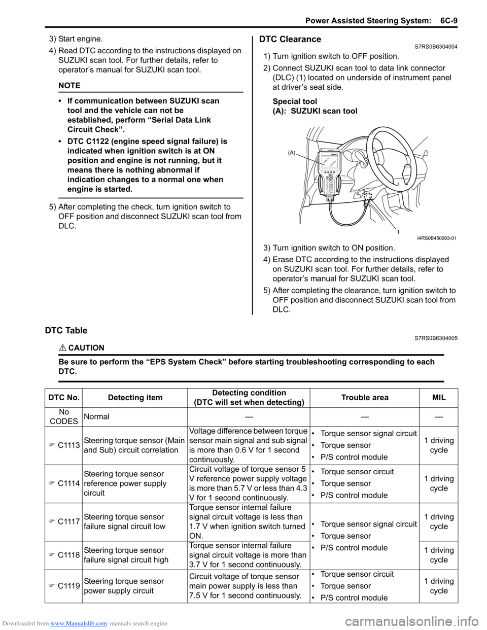
2) Connect SUZUKI scan tool to data link connector (DLC) (1) located on underside of instrument panel
at driver’s seat side.
Special tool
(A): SUZUKI scan tool
3) Turn ignition switch to ON position.
4) Erase DTC according to the instructions displayed on SUZUKI scan tool. For further details, refer to
operator’s manual for SUZUKI scan tool.
5) After completing the clearance, turn ignition switch to OFF position and disconnect SUZUKI scan tool from
DLC.
DTC TableS7RS0B6304005
CAUTION!
Be sure to perform the “EPS Syst em Check” before starting troubleshooting corresponding to each
DTC.
(A)
1
I4RS0B450003-01
DTC No. Detecting item Detecting condition
(DTC will set when detecting) Trouble area MIL
No
CODES Normal — — —
�) C1113 Steering torque sensor (Main
and Sub) circuit correlation Voltage difference between torque
sensor main signal and sub signal
is more than 0.6 V for 1 second
continuously. • Torque sensor signal circuit
• Torque sensor
• P/S control module
1 driving
cycle
�) C1114 Steering torque sensor
reference power supply
circuit Circuit voltage of torque sensor 5
V reference power supply voltage
is more than 5.7 V or less than 4.3
V for 1 second continuously. • Torque sensor circuit
• Torque sensor
• P/S control module
1 driving
cycle
�) C1117 Steering torque sensor
failure signal circuit low Torque sensor internal failure
signal circuit voltage is less than
1.7 V when ignition switch turned
ON.
• Torque sensor signal circuit
• Torque sensor
• P/S control module1 driving
cycle
�) C1118 Steering torque sensor
failure signal circuit high Torque sensor internal failure
signal circuit voltage is more than
3.7 V for 1 second continuously. 1 driving
cycle
�) C1119 Steering torque sensor
power supply circuit Circuit voltage of torque sensor
main power supply
is less than
7.5 V for 1 second continuously. • Torque sensor circuit
• Torque sensor
• P/S control module
1 driving
cycle
Page 892 of 1496

Downloaded from www.Manualslib.com manuals search engine 6C-10 Power Assisted Steering System:
�) C1121 No vehicle speed signal
(60 seconds or more) Vehicle speed signal is 0 km/h
even though engine speed is
more than 4000 rpm for more than
60 seconds continuously (before
elapse of 5 min from engine start)
or vehicle speed signal is 0 km/h
even though engine speed is
more than 2500 rpm for more than
60 seconds continuously (after
elapse of 5 min for engine start). • Vehicle speed signal circuit
• Wheel speed sensor
•ECM
• P/S control module
• ABS control module
• CAN communication circuit
Not
applicable
�) C1122 Engine speed signal Engine speed signal is less than
220 rpm for more than 0.8
seconds.
or
Engine speed signal is less than
220 rpm for more than 20
seconds continuously even
though vehicle speed signal is
more than 50 km/h.• Engine speed signal circuit
•ECM
• P/S control module
• Vehicle speed signal
1 driving
cycle
�) C1123 No vehicle speed signal
(30 seconds or more) Vehicle speed signal is 0 km/h
with continuously more than 3
driving cycles even though engine
speed is more than 4000 rpm for
more than 30 seconds
continuously (before elapse of 5
min from engine start).
or
vehicle speed signal is 0 km/h
with continuously more than 3
driving cycles even though engine
speed is more than 2500 rpm for
more than 30 seconds
continuously (after elapse of 5 min
for engine start). • Vehicle speed signal circuit
• Wheel speed sensor
•ECM
• P/S control module
• ABS control module
• CAN communication circuit
3 driving
cycles
�) C1124 Vehicle speed performance
(Impossible deceleration) Vehicle speed signal is less than 5
km/h for more
than 5 seconds
continuously with more than
specified deceleration speed (–20
m/s
2) from over 20 km/h. Not
applicable
�) C1141 P/S motor circuit voltage Voltage between both motor drive
circuits is more than 8.5 V or less
than 0.2 V for 0.5 seconds
continuously while motor is not
drived.
• P/S motor circuit
• P/S motor
• P/S control module1 driving
cycle
�) C1142 P/S motor circuit range /
performance Measured motor drive current is
more than 10 A as compared with
target motor drive current. 1 driving
cycle
DTC No. Detecting item
Detecting condition
(DTC will set when detecting) Trouble area MIL
Page 893 of 1496
Downloaded from www.Manualslib.com manuals search engine Power Assisted Steering System: 6C-11
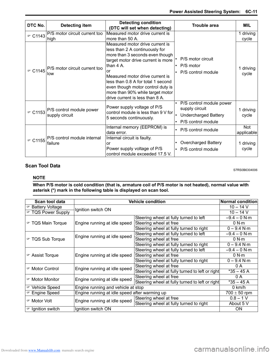
Scan Tool DataS7RS0B6304006
NOTE
When P/S motor is cold condition (that is, armature coil of P/S motor is not heated), normal value with
asterisk (*) mark in the following table is displayed on scan tool.
�) C1143 P/S motor circuit current too
high Measured motor drive current is
more than 50 A.
• P/S motor circuit
• P/S motor
• P/S control module1 driving
cycle
�) C1145 P/S motor circuit current too
low Measured motor drive current is
less than 2 A continuously for
more than 3 seconds even though
target motor drive current is more
than 4 A.
or
Measured motor drive current is
less than 0.8 A for total 1 second
even though motor control duty is
more than 90% while target motor
drive current is less than 8 A. 1 driving
cycle
�) C1153 P/S control module power
supply circuit Power supply voltage of P/S
control module is less than 9 V for
5 seconds continuously. • P/S control module power
supply circuit
• Undercharged Battery
• P/S control module 1 driving
cycle
�) C1155 P/S control module internal
failure Internal memory (EEPROM) is
data error.
• P/S control moduleNot
applicable
Internal circuit is faulty.
or
Power supply voltage of P/S
control module exceeded 17.5 V. • Overcharged Battery
• P/S control module
1 driving
cycle
DTC No. Detecting item
Detecting condition
(DTC will set when detecting) Trouble area MIL
Scan tool data
Vehicle conditionNormal condition
�) Battery Voltage
Ignition switch ON 10 – 14 V
�) TQS Power Supply 10 – 14 V
�) TQS Main Torque Engine running at idle speed Steering wheel at fully turned to left –9.4 – 0 N
⋅m
Steering wheel at free 0 N⋅m
Steering wheel at fully turned to right 0 – 9.4 N ⋅m
�) TQS Sub Torque Engine running at idle speed Steering wheel at fully turned to left –9.4 – 0 N
⋅m
Steering wheel at free 0 N⋅m
Steering wheel at fully turned to right 0 – 9.4 N ⋅m
�) Assist Torque Engine running at idle speed Steering wheel at fully turned to left –9.4 – 0 N
⋅m
Steering wheel at free 0 N⋅m
Steering wheel at fully turned to right 0 – 9.4 N ⋅m
�) Motor Control Engine running at idle speed Steering wheel at free
0 A
Steering wheel at fully turned to left or right *35 – 45 A
�) Motor Monitor Engine running at idle speed Steering wheel at free
0 A
Steering wheel at fully turned to left or right *35 – 45 A
�) Vehicle Speed Engine running and vehicle at stop 0 km/h
�) Engine Speed Engine running at idle speed after warming up 700 ± 50 rpm
�) Motor Volt Engine running at idle speed Steering wheel at free
0.8 – 1 V
Steering wheel at fully turned to right About 5 V
�) Ignition switch Ignition switch ON ON
Page 894 of 1496
Downloaded from www.Manualslib.com manuals search engine 6C-12 Power Assisted Steering System:
Scan Tool Data Definitions
Battery Voltage
This parameter indicates battery positive voltage.
TQS Power Supply (Torque Sensor Power Supply, V)
This parameter indicates the power supply voltage which
the P/S control module supplies to the torque sensor.
TQS Main Torque (Torque Sensor Main Torque, N ⋅m)
The torque sensor is installed to detect the steering force
and the steering directio n. It consists of two
potentiometers and the main torque sensor is one of
these.
TQS Sub Torque (Torque Sensor Sub Torque, N ⋅m)
The torque sensor is installed to detect the steering force
and the steering directio n. It consists of two
potentiometers and the sub-torque sensor is one of
these. Its output characteristics are compared with those
of the main torque sensor.
Assist Torque (N ⋅m)
This parameter is an internal parameter of the P/S
control module. It is obtained by computing the torque
sensor input signal. Motor Control (Motor Control Current, A)
Based on the input signal, the P/S control module
determines the assist amount
and controls the current to
the motor suitable for that a ssist amount. This parameter
indicates that control value.
Motor Monitor (Motor Monitor Current, A)
This parameter indicates the actually measured value of
the current flowing to the motor. The motor circuit
condition is diagnosed by co mparing this parameter with
“Motor Control” parameter described previously.
Vehicle Speed (km/h, MPH)
Vehicle speed signal is fed from BCM. P/S control
module determines the amount of power assist based on
this vehicle speed signal and the torque sensor signal.
Engine Speed (rpm)
Engine speed signal is fed from the ECM so that it can
be used for trouble diagnos is of the electric power
steering system.
Motor Volt (V)
This parameter indicates the voltage between motor
terminals.
Ignition switch (ON, OFF)
This parameter indicates the condition of the power
supply through the ignition switch.
Visual InspectionS7RS0B6304007
Visually check the following pats and system.
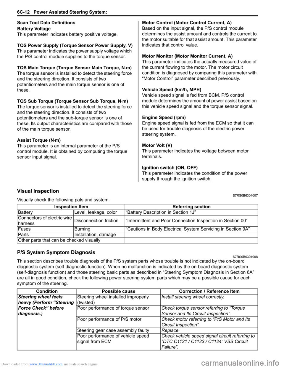
P/S System Symptom DiagnosisS7RS0B6304008
This section describes trouble diagnosis of the P/S system parts whose trouble is not indicated by the on-board
diagnostic system (self-diagnostic functi on). When no malfunction is indicated by the on-board diagnostic system
(self-diagnosis function) and those stee ring basic parts as described in “Steering Symptom Diagnosis in Section 6A”
are all in good condition, check the following power steer ing system parts which may be a possible cause for each
symptom of the steering. Inspection Item Referring section
Battery Level, leakage, color “Batte ry Description in Section 1J”
Connectors of electric wire
harness Disconnection friction “Intermittent and Poor
Connection Inspection in Section 00”
Fuses Burning “Cautions in Body Electric al System Servicing in Section 9A”
Parts Installation, damage
Other parts that can be checked visually
Condition Possible cause Correction / Reference Item
Steering wheel feels
heavy (Perform “Steering
Force Check” before
diagnosis.) Steering wheel installed improperly
(twisted)
Install steering wheel correctly.
Poor performance of torque sensor Check torque sensor referring to “Torque
Sensor and Its Circuit Inspection”.
Poor performance of P/S motor Check motor referring to “P/S Motor and Its
Circuit Inspection”.
Steering gear case assembly faulty Replace.
Poor performance of vehicle speed
signal from ECM Check vehicle speed signal circuit referring to
“DTC C1121 / C1123 / C1124: VSS Circuit
Failure”.
Page 895 of 1496
Downloaded from www.Manualslib.com manuals search engine Power Assisted Steering System: 6C-13
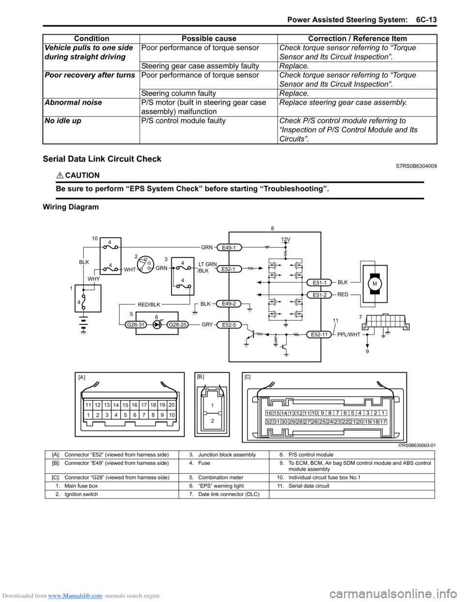
Serial Data Link Circuit CheckS7RS0B6304009
CAUTION!
Be sure to perform “EPS System Check” before starting “Troubleshooting”.
Wiring DiagramVehicle pulls to one side
during straight driving
Poor performance of torque sensor
Check torque sensor referring to “Torque
Sensor and Its Circuit Inspection”.
Steering gear case assembly faulty Replace.
Poor recovery after turns Poor performance of torque sensor Check torque sensor referring to “Torque
Sensor and Its Circuit Inspection”.
Steering column faulty Replace.
Abnormal noise P/S motor (built in steering gear case
assembly) malfunction Replace steering gear case assembly.
No idle up P/S control module faulty Check P/S control module referring to
“Inspection of P/S Control Module and Its
Circuits”.
Condition Possible cause Correction / Reference Item
MBLK
RED
E52-11 E51-1
E51-2PPL/WHT
[A ]
12
3
4 5 67
89
11
10
12 13
141516
17 18 19 2010 9 8 7654 3 21
16 15 14 13 12 11
26 25 24 2322 21 20 19 18 17
32 31 30 29 28 27
[C]
8
79
12V
[B ]
11
12
GRY
LT GRN
/BLK
E52-1
E52-5
E49-1
GRNGRNWHTBLK
WHY
G28-25G28-31
RED/BLK
10
3
4
4
5 6
4
4
1 2
4
E49-2BLK
I7RS0B630003-01
[A]: Connector “E52” (viewed from harness side) 3. Junction block assembly 8. P/S control module
[B]: Connector “E49” (viewed from harness side) 4. Fuse 9. T o ECM, BCM, Air bag SDM control module and ABS control
module assembly
[C]: Connector “G28” (viewed from harness side) 5. Comb ination meter 10. Individual circuit fuse box No.1
1. Main fuse box 6. “EPS” warning light 11. Serial data circuit
2. Ignition switch 7. Date link connector (DLC)
Page 896 of 1496
Downloaded from www.Manualslib.com manuals search engine 6C-14 Power Assisted Steering System:
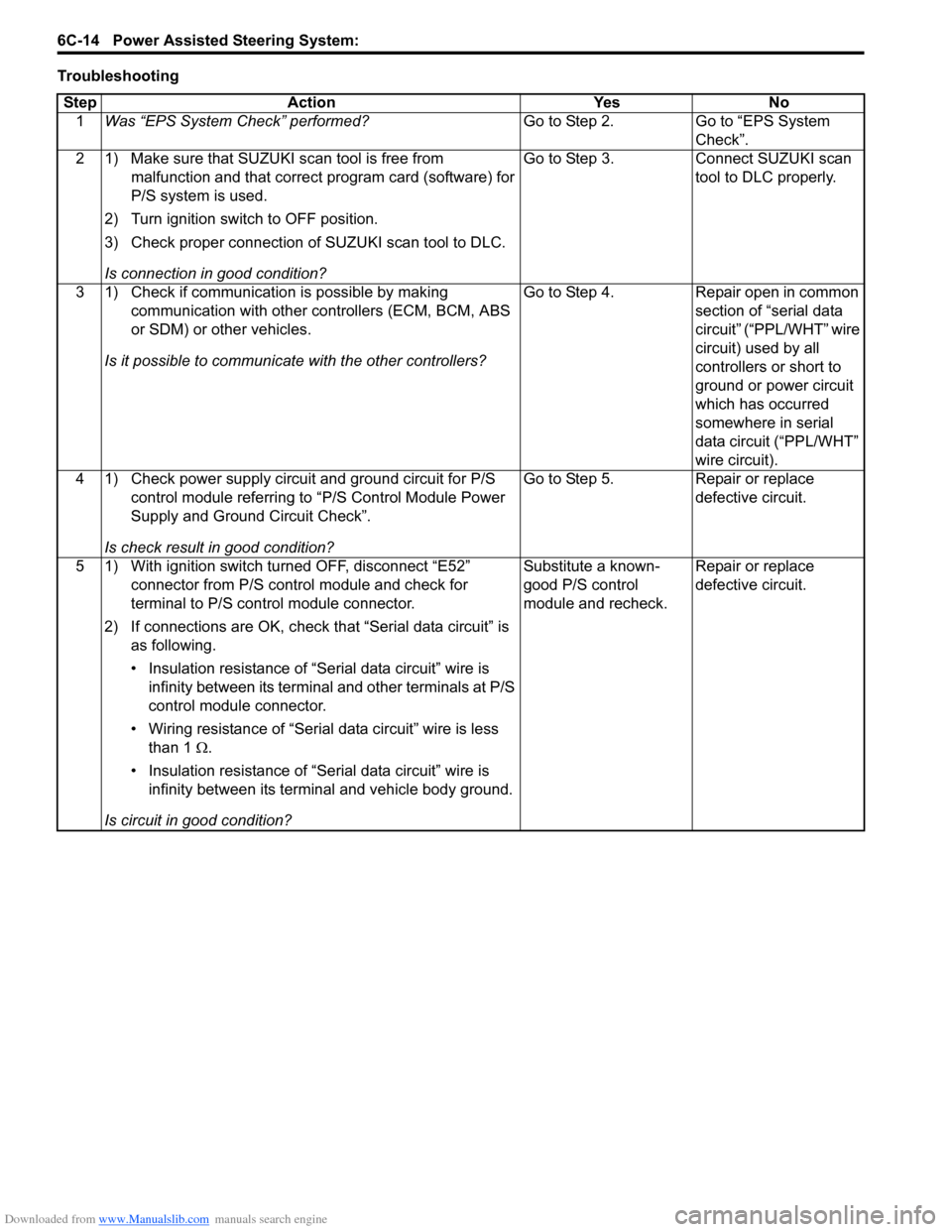
TroubleshootingStep Action Yes No 1 Was “EPS System Check” performed? Go to Step 2. Go to “EPS System
Check”.
2 1) Make sure that SUZUKI scan tool is free from malfunction and that correct program card (software) for
P/S system is used.
2) Turn ignition switch to OFF position.
3) Check proper connection of SUZUKI scan tool to DLC.
Is connection in good condition? Go to Step 3. Connect SUZUKI scan
tool to DLC properly.
3 1) Check if communication is possible by making communication with other controllers (ECM, BCM, ABS
or SDM) or other vehicles.
Is it possible to communic ate with the other controllers? Go to Step 4. Repair open in common
section of “serial data
circuit” (“PPL/WHT” wire
circuit) used by all
controllers or short to
ground or power circuit
which has occurred
somewhere in serial
data circuit (“PPL/WHT”
wire circuit).
4 1) Check power supply circuit and ground circuit for P/S control module referring to “P/S Control Module Power
Supply and Ground Circuit Check”.
Is check result in good condition? Go to Step 5. Repair or replace
defective circuit.
5 1) With ignition switch turned OFF, disconnect “E52” connector from P/S control module and check for
terminal to P/S control module connector.
2) If connections are OK, check t hat “Serial data circuit” is
as following.
• Insulation resistance of “Serial data circuit” wire is infinity between its terminal and other terminals at P/S
control module connector.
• Wiring resistance of “Seria l data circuit” wire is less
than 1 Ω.
• Insulation resistance of “Serial data circuit” wire is infinity between its terminal and vehicle body ground.
Is circuit in good condition? Substitute a known-
good P/S control
module and recheck.
Repair or replace
defective circuit.
Page 897 of 1496
Downloaded from www.Manualslib.com manuals search engine Power Assisted Steering System: 6C-15
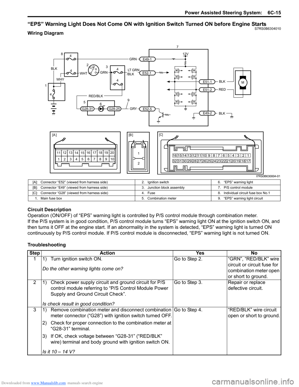
“EPS” Warning Light Does Not Come ON with Ignition Switch Turned ON before Engine StartsS7RS0B6304010
Wiring Diagram
Circuit Description
Operation (ON/OFF) of “EPS” warning light is controlled by P/S control module through combination meter.
If the P/S system is in good condition, P/S control module turns “ EPS” warning light ON at the ignition switch ON, and
then turns it OFF at the engine start. If an abnormality in the system is detected, “EPS” warning light is turned ON
continuously by P/S control module. If P/S control module is disconnected, “EPS” warning light is not turned ON.
Troubleshooting
MBLK
REDE51-1
E51-2
[A ]
12 3
4 5 67
89
11
10
12 13
141516
17 18 19 2010 9 8 7654 3 21
16 15 14 13 12 11
26 25 24 2322 21 20 19 18 17
32 31 30 29 28 27
[C]
7
12V
E49-2BLK
[B ]
1 2
GRY
LT GRN
/BLK
E52-1
E52-5
E49-1
GRNGRNWHTBLK
WHY
G28-25G28-31
RED/BLK
8
3
4
4
5 6
4
4
1 2
4
9
I7RS0B630004-01
[A]: Connector “E52” (viewed from harness side) 2. Ignition switch6. “EPS” warning light
[B]: Connector “E49” (viewed from harness side) 3. Junction block assembly7. P/S control module
[C]: Connector “G28” (viewed from harness si de)4. Fuse 8. Individual circuit fuse box No.1
1. Main fuse box 5. Combination meter9. “EPS” warning light circuit
StepAction YesNo
1 1) Turn ignition switch ON.
Do the other warning lights come on? Go to Step 2.
“GRN”, “RED/BLK” wire
circuit or circuit fuse for
combination meter open
or short to ground.
2 1) Check power supply circuit and ground circuit for P/S control module referring to “P/S Control Module Power
Supply and Ground Circuit Check”.
Is check result in good condition? Go to Step 3.
Repair or replace
defective circuit.
3 1) Remove combination meter and disconnect combination meter connector (“G28”) with ignition switch turned OFF.
2) Check for proper connection to the combination meter at “G28-31” terminal.
3) If OK, check voltage between “G28-31” (“RED/BLK” wire) terminal and body ground with ignition switch ON.
Is it 10 – 14 V? Go to Step 4.
“RED/BLK” wire circuit
open or short to ground.
Page 898 of 1496
Downloaded from www.Manualslib.com manuals search engine 6C-16 Power Assisted Steering System:
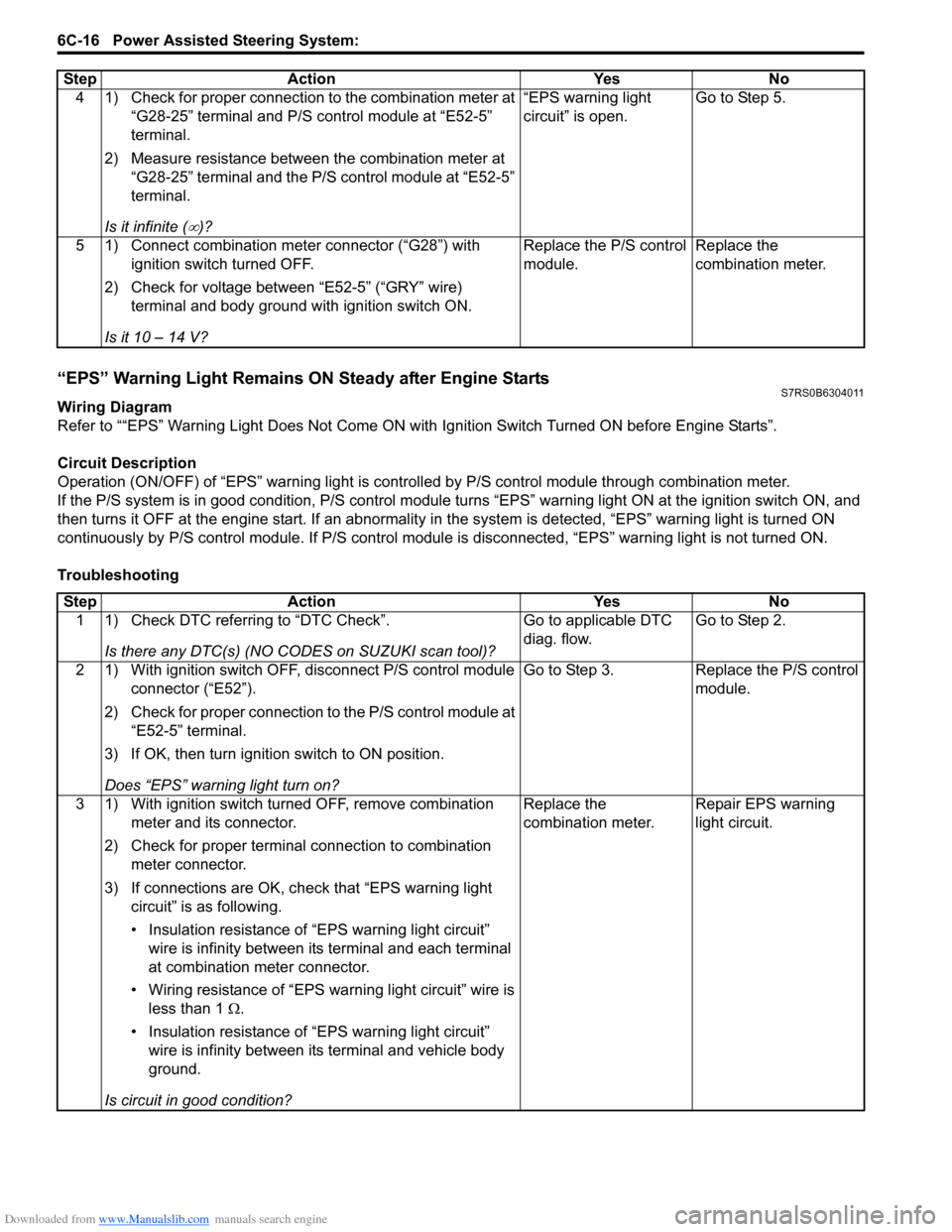
“EPS” Warning Light Remains ON Steady after Engine StartsS7RS0B6304011
Wiring Diagram
Refer to ““EPS” Warning Light Does Not Come ON with Ignition Switch Turned ON before Engine Starts”.
Circuit Description
Operation (ON/OFF) of “EPS” warning light is controlled by P/S c ontrol module through combination meter.
If the P/S system is in good condition, P/S control module tu rns “EPS” warning light ON at the ignition switch ON, and
then turns it OFF at the engine start. If an abnormality in the system is detected, “EPS” warning light is turned ON
continuously by P/S control module. If P/S control module is disconnected, “EPS” warning light is not turned ON.
Troubleshooting 4 1) Check for proper connection to the combination meter at
“G28-25” terminal and P/S control module at “E52-5”
terminal.
2) Measure resistance between the combination meter at “G28-25” terminal and the P/S control module at “E52-5”
terminal.
Is it infinite (
∞)? “EPS warning light
circuit” is open.
Go to Step 5.
5 1) Connect combination meter connector (“G28”) with ignition switch turned OFF.
2) Check for voltage between “E52-5” (“GRY” wire) terminal and body ground with ignition switch ON.
Is it 10 – 14 V? Replace the P/S control
module.
Replace the
combination meter.
Step
Action YesNo
Step Action YesNo
1 1) Check DTC referring to “DTC Check”.
Is there any DTC(s) (NO CODES on SUZUKI scan tool)? Go to applicable DTC
diag. flow.
Go to Step 2.
2 1) With ignition switch OFF, disconnect P/S control module connector (“E52”).
2) Check for proper connection to the P/S control module at “E52-5” terminal.
3) If OK, then turn ignition switch to ON position.
Does “EPS” warning light turn on? Go to Step 3.
Replace the P/S control
module.
3 1) With ignition switch turned OFF, remove combination meter and its connector.
2) Check for proper terminal connection to combination meter connector.
3) If connections are OK, ch eck that “EPS warning light
circuit” is as following.
• Insulation resistance of “EPS warning light circuit” wire is infinity between its terminal and each terminal
at combination meter connector.
• Wiring resistance of “EPS wa rning light circuit” wire is
less than 1 Ω.
• Insulation resistance of “EPS warning light circuit” wire is infinity between its terminal and vehicle body
ground.
Is circuit in good condition? Replace the
combination meter.
Repair EPS warning
light circuit.
Page 899 of 1496
Downloaded from www.Manualslib.com manuals search engine Power Assisted Steering System: 6C-17
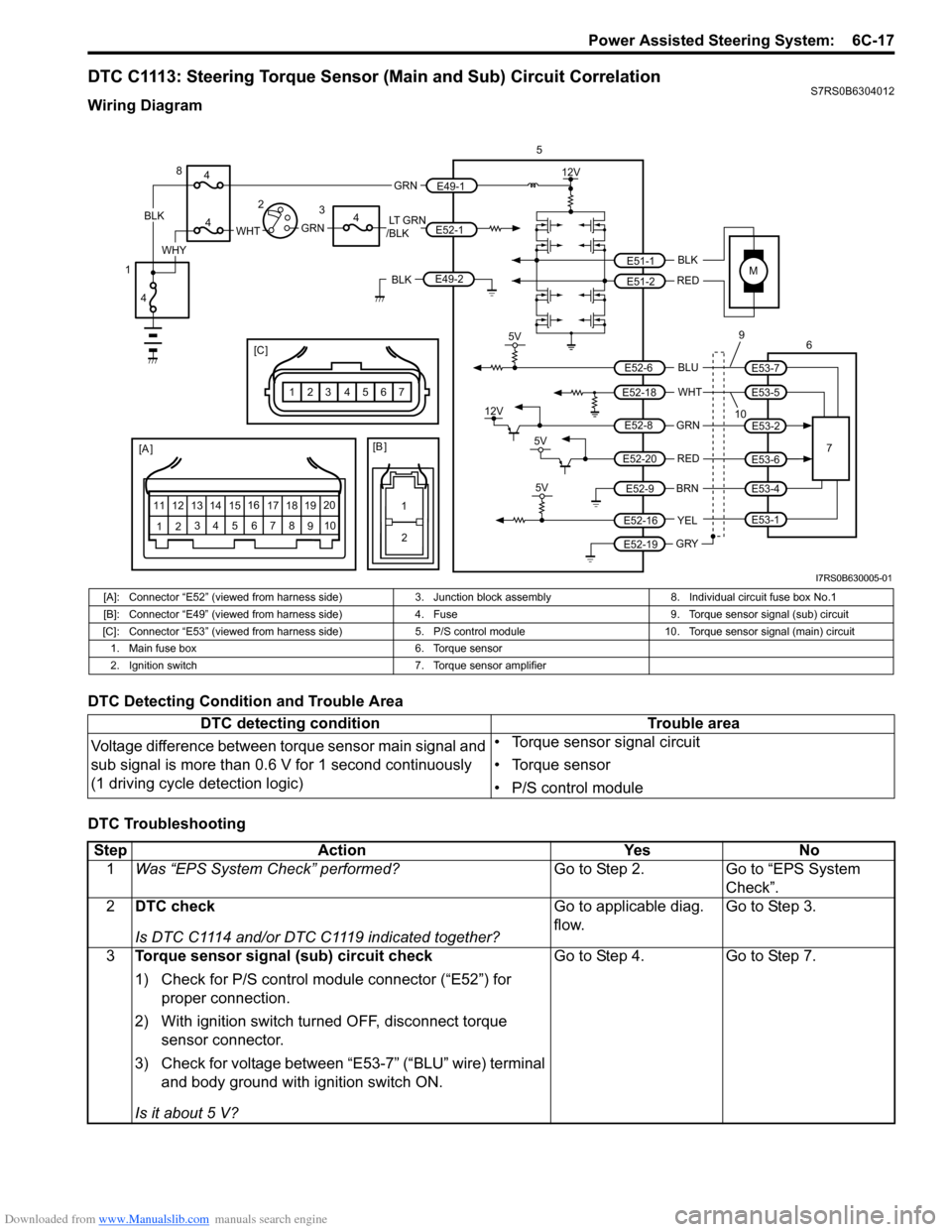
DTC C1113: Steering Torque Sensor (Main and Sub) Circuit CorrelationS7RS0B6304012
Wiring Diagram
DTC Detecting Condition and Trouble Area
DTC Troubleshooting
M
5V
BLK
RED
WHT BLU
GRN
BRN YEL
E51-1
E51-2
E52-18
E53-5
E53-7
E52-6
E52-8
E53-2
E52-9
E52-16
E52-19
GRY
[A ]
12 3
4 5 67
89
11
10
12 13
141516
17 18 19 20
5
67
12V
5V
5V
12V
REDE52-20E53-6
E53-4
E53-1
109
1
2
[B ]
[C ]
7654321
LT GRN
/BLKE52-1 E49-1
GRNGRNWHTBLK
WHY
8
3
4
4
4
4
1 2
E49-2BLK
I7RS0B630005-01
[A]: Connector “E52” (viewed from harness side)
3. Junction block assembly 8. Individual circuit fuse box No.1
[B]: Connector “E49” (viewed from harness side )4. Fuse 9. Torque sensor signal (sub) circuit
[C]: Connector “E53” (viewed from harness side) 5. P/S control module 10. Torque sensor signal (main) circuit
1. Main fuse box 6. Torque sensor
2. Ignition switch 7. Torque sensor amplifier
DTC detecting condition Trouble area
Voltage difference between torque sensor main signal and
sub signal is more than 0.6 V for 1 second continuously
(1 driving cycle detection logic) • Torque sensor signal circuit
• Torque sensor
• P/S control module
Step
Action YesNo
1 Was “EPS System Check” performed? Go to Step 2.Go to “EPS System
Check”.
2 DTC check
Is DTC C1114 and/or DTC C1119 indicated together? Go to applicable diag.
flow.
Go to Step 3.
3 Torque sensor signal (sub) circuit check
1) Check for P/S control module connector (“E52”) for
proper connection.
2) With ignition switch turned OFF, disconnect torque sensor connector.
3) Check for voltage between “E53-7” (“BLU” wire) terminal and body ground with ignition switch ON.
Is it about 5 V? Go to Step 4.
Go to Step 7.
Page 900 of 1496
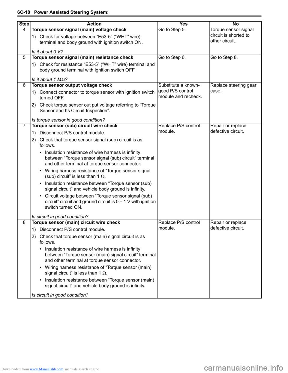
Downloaded from www.Manualslib.com manuals search engine 6C-18 Power Assisted Steering System:
4Torque sensor signal (main) voltage check
1) Check for voltage between “E53-5” (“WHT” wire)
terminal and body ground with ignition switch ON.
Is it about 0 V? Go to Step 5. Torque sensor signal
circuit is shorted to
other circuit.
5 Torque sensor signal (main) resistance check
1) Check for resistance “E53-5” (“WHT” wire) terminal and
body ground terminal with ignition switch OFF.
Is it about 1 M
Ω? Go to Step 6. Go to Step 8.
6 Torque sensor output voltage check
1) Connect connector to torque sensor with ignition switch
turned OFF.
2) Check torque sensor out put voltage referring to “Torque Sensor and Its Circuit Inspection”.
Is torque sensor in good condition? Substitute a known-
good P/S control
module and recheck.
Replace steering gear
case.
7 Torque sensor (sub) circuit wire check
1) Disconnect P/S control module.
2) Check that torque sensor signal (sub) circuit is as
follows.
• Insulation resistance of wire harness is infinity between “Torque sensor signal (sub) circuit” terminal
and other terminal at torque sensor connector.
• Wiring harness resistance of “Torque sensor signal (sub) circuit” is less than 1 Ω.
• Insulation resistance between “Torque sensor (sub) signal circuit” and vehicle body ground is infinity.
• Circuit voltage between “Torque sensor signal (sub) circuit” circuit and ground circuit is 0 – 1 V with ignition
switch turned ON.
Is circuit in good condition? Replace P/S control
module.
Repair or replace
defective circuit.
8 Torque sensor (main) circuit wire check
1) Disconnect P/S control module.
2) Check that torque sensor (main) signal circuit is as
follows.
• Insulation resistance of wire harness is infinity between “Torque sensor (main) signal circuit” terminal
and other terminal at torque sensor connector.
• Wiring harness resistance of “Torque sensor (main) signal circuit” is less than 1 Ω.
• Insulation resistance between “Torque sensor (main) signal circuit” and vehicle body ground is infinity.
Is circuit in good condition? Replace P/S control
module.
Repair or replace
defective circuit.
Step Action Yes No