PS control module SUZUKI SWIFT 2008 2.G Service Workshop Manual
[x] Cancel search | Manufacturer: SUZUKI, Model Year: 2008, Model line: SWIFT, Model: SUZUKI SWIFT 2008 2.GPages: 1496, PDF Size: 34.44 MB
Page 901 of 1496
Downloaded from www.Manualslib.com manuals search engine Power Assisted Steering System: 6C-19
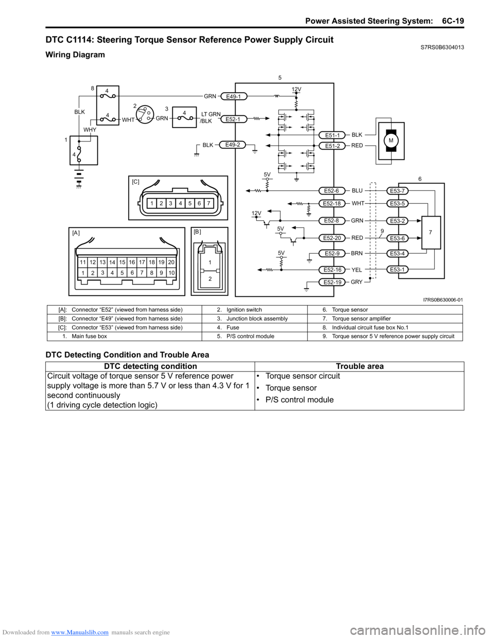
DTC C1114: Steering Torque Sensor Reference Power Supply CircuitS7RS0B6304013
Wiring Diagram
DTC Detecting Condition and Trouble Area
M
5V
BLK
RED
WHT BLU
GRN
BRN YEL
E51-1
E51-2
E52-18
E53-5
E53-7
E52-6
E52-8
E53-2
E52-9
E52-16
E52-19
GRY
5
67
12V
5V
5V
12V
REDE52-20E53-6
E53-4
E53-1
9[A ]
12 3
4 5 67
89
11
10
12 13
141516
17 18 19 20
1
2
[B ]
[C ]
7654321
LT GRN
/BLKE52-1 E49-1
GRNGRNWHTBLK
WHY
8
3
4
4
4
4
1 2
E49-2BLK
I7RS0B630006-01
[A]: Connector “E52” (viewed from harness side)
2. Ignition switch6. Torque sensor
[B]: Connector “E49” (viewed from harness side) 3. Junction block assembly 7. Torque sensor amplifier
[C]: Connector “E53” (viewed from harness si de)4. Fuse 8. Individual circuit fuse box No.1
1. Main fuse box 5. P/S control module9. Torque sensor 5 V reference power supply circuit
DTC detecting condition Trouble area
Circuit voltage of torque sensor 5 V reference power
supply voltage is more than 5.7 V or less than 4.3 V for 1
second continuously
(1 driving cycle detection logic) • Torque sensor circuit
• Torque sensor
• P/S control module
Page 902 of 1496
Downloaded from www.Manualslib.com manuals search engine 6C-20 Power Assisted Steering System:
DTC TroubleshootingStep Action Yes No 1 Was “EPS System Check” performed? Go to Step 2. Go to “EPS System
Check”.
2 DTC check
Is DTC C1153 and/or DTC C1155 indicated together? Go to applicable DTC
diag. flow.
Go to Step 3.
3 Torque sensor 5 V reference power supply circuit
voltage check
1) With ignition switch turned OFF, disconnect torque
sensor connector and check for proper terminal
connection to torque sensor connector.
2) If connections are OK, check for voltage between “E53- 6” (“RED” wire) terminal and body ground with ignition
switch ON.
Is it approx. 5 V? Go to Step 4. Go to Step 5.
4 Torque sensor 5 V reference power supply circuit check
1) With ignition switch turned OFF, connect torque sensor
connector.
2) Check for P/S control module connector (“E52”) for proper connection.
3) Turn ignition switch ON.
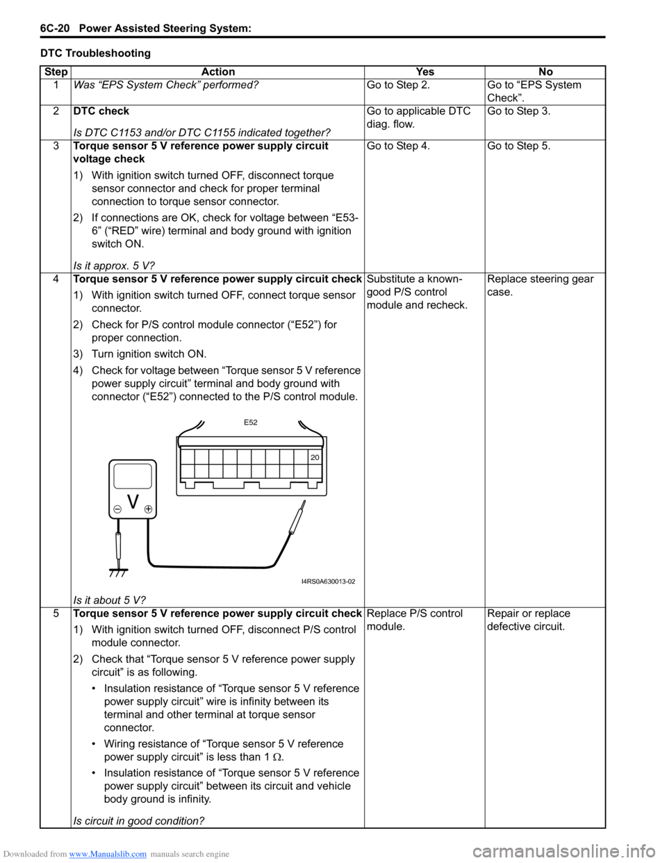
4) Check for voltage between “Torque sensor 5 V reference power supply circuit” terminal and body ground with
connector (“E52”) connected to the P/S control module.
Is it about 5 V? Substitute a known-
good P/S control
module and recheck.
Replace steering gear
case.
5 Torque sensor 5 V reference power supply circuit check
1) With ignition switch turned OFF, disconnect P/S control
module connector.
2) Check that “Torque sensor 5 V reference power supply circuit” is as following.
• Insulation resistance of “Torque sensor 5 V reference power supply circuit” wire is infinity between its
terminal and other terminal at torque sensor
connector.
• Wiring resistance of “Torque sensor 5 V reference power supply circuit” is less than 1 Ω.
• Insulation resistance of “Torque sensor 5 V reference power supply circuit” between its circuit and vehicle
body ground is infinity.
Is circuit in good condition? Replace P/S control
module.
Repair or replace
defective circuit.
20
E52
I4RS0A630013-02
Page 903 of 1496
Downloaded from www.Manualslib.com manuals search engine Power Assisted Steering System: 6C-21
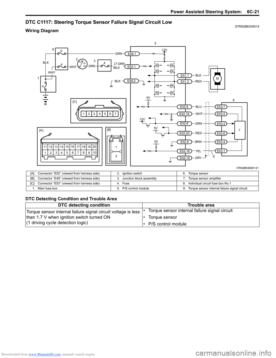
DTC C1117: Steering Torque Sensor Failure Signal Circuit LowS7RS0B6304014
Wiring Diagram
DTC Detecting Condition and Trouble Area
M
5V
BLK
RED
WHT BLU
GRN
BRN YEL
E51-1
E51-2
E52-18
E53-5
E53-7
E52-6
E52-8
E53-2
E52-9
E52-16
E52-19
GRY
[A ]
12 3
4 5 67
89
11
10
12 13
141516
17 18 19 20
5
67
12V
5V
5V
12V
REDE52-20E53-6
E53-4
E53-1
9
12
[B]
[C ]
7654321
LT GRN
/BLKE52-1 E49-1
GRNGRNWHTBLK
WHY
8
3
4
4
4
4
1 2
E49-2BLK
I7RS0B630007-01
[A]: Connector “E52” (viewed from harness side)
2. Ignition switch6. Torque sensor
[B]: Connector “E49” (viewed from harness side) 3. Junction block assembly7. Torque sensor amplifier
[C]: Connector “E53” (viewed from harness side) 4. Fuse8. Individual circuit fuse box No.1
1. Main fuse box 5. P/S control module9. Torque sensor internal failure signal circuit
DTC detecting condition Trouble area
Torque sensor internal failure signal circuit voltage is less
than 1.7 V when ignition switch turned ON
(1 driving cycle detection logic) • Torque sensor internal failure signal circuit
• Torque sensor
• P/S control module
Page 904 of 1496
Downloaded from www.Manualslib.com manuals search engine 6C-22 Power Assisted Steering System:
DTC Troubleshooting
DTC C1118: Steering Torque Sensor Failure Signal Circuit HighS7RS0B6304015
Wiring Diagram
Refer to “DTC C1117: Steering Torque Sensor Failure Signal Circuit Low”.
DTC Detecting Condition and Trouble AreaStep Action Yes No
1 Was “EPS System Check” performed? Go to Step 2. Go to “EPS System
Check”.
2 DTC check
Is DTC C1113, C1114 and/or DTC C1119 indicated together? Go to applicable diag.
flow.
Go to Step 3.
3 Torque sensor internal failure signal circuit check
1) Check for P/S control module connector (“E52”) for
proper connection.
2) With ignition switch turned OFF, disconnect torque sensor connector.
3) Check for voltage between “E53-1” (“YEL” wire) terminal and body ground with ignition switch ON.
Is it about 5 V? Go to Step 4. Go to Step 5.
4 Torque sensor internal failure signal circuit check
1) With ignition switch turned OFF, connect torque sensor
connector.
2) Check that voltage between “E52-16” (“YEL” wire) terminal and body ground is about 5V at the moment of
ignition switch turned ON.
Is it about 5 V? Substitute a known-
good P/S control
module and recheck.
Replace steering gear
case.
5 Torque sensor internal failure signal circuit wire check
1) Disconnect P/S control module.
2) Check that torque sensor failure signal circuit is as
follows.
• Insulation resistance of wire harness is infinity between “Torque sensor internal failure signal circuit”
terminal and other terminal at torque sensor
connector.
• Insulation resistance between “Torque sensor internal failure signal circuit” and vehicle body ground is
infinity.
Is circuit in good condition? Substitute a known-
good P/S control
module and recheck.
Repair or replace
defective circuit.
DTC detecting condition
Trouble area
Torque sensor internal failure signal circuit voltage is more
than 3.7 V for 1 second continuously
(1 driving cycle detection logic) • Torque sensor signal circuit
• Torque sensor internal failure signal circuit
• Torque sensor
• P/S control module
Page 905 of 1496
Downloaded from www.Manualslib.com manuals search engine Power Assisted Steering System: 6C-23
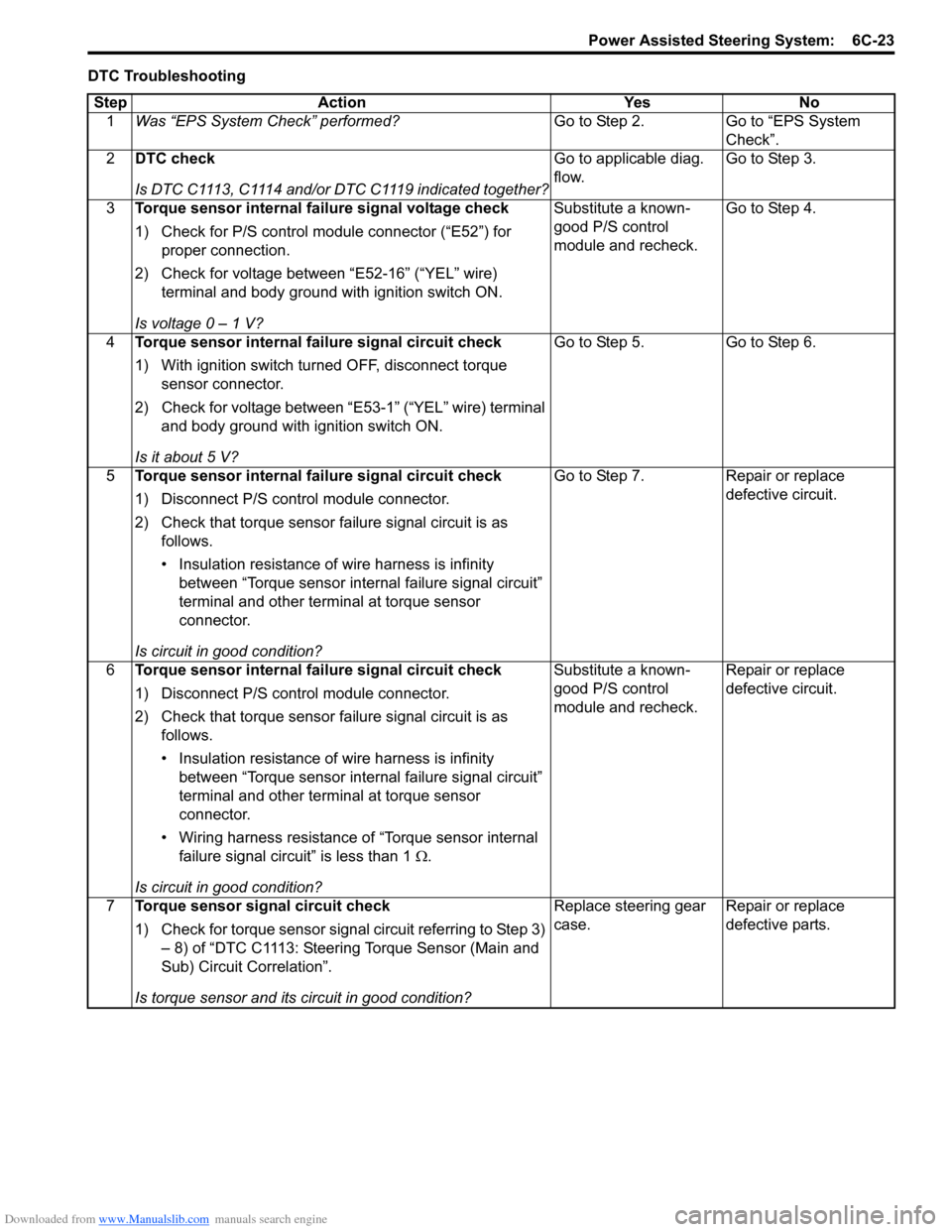
DTC TroubleshootingStep Action Yes No 1 Was “EPS System Check” performed? Go to Step 2. Go to “EPS System
Check”.
2 DTC check
Is DTC C1113, C1114 and/or DTC C1119 indicated together? Go to applicable diag.
flow.
Go to Step 3.
3 Torque sensor internal failure signal voltage check
1) Check for P/S control module connector (“E52”) for
proper connection.
2) Check for voltage between “E52-16” (“YEL” wire) terminal and body ground with ignition switch ON.
Is voltage 0 – 1 V? Substitute a known-
good P/S control
module and recheck.
Go to Step 4.
4 Torque sensor internal failure signal circuit check
1) With ignition switch turned OFF, disconnect torque
sensor connector.
2) Check for voltage between “E53-1” (“YEL” wire) terminal and body ground with ignition switch ON.
Is it about 5 V? Go to Step 5. Go to Step 6.
5 Torque sensor internal failure signal circuit check
1) Disconnect P/S control module connector.
2) Check that torque sensor failure signal circuit is as
follows.
• Insulation resistance of wire harness is infinity between “Torque sensor internal failure signal circuit”
terminal and other terminal at torque sensor
connector.
Is circuit in good condition? Go to Step 7. Repair or replace
defective circuit.
6 Torque sensor internal failure signal circuit check
1) Disconnect P/S control module connector.
2) Check that torque sensor failure signal circuit is as
follows.
• Insulation resistance of wire harness is infinity between “Torque sensor internal failure signal circuit”
terminal and other terminal at torque sensor
connector.
• Wiring harness resistance of “Torque sensor internal failure signal circuit” is less than 1 Ω.
Is circuit in good condition? Substitute a known-
good P/S control
module and recheck.
Repair or replace
defective circuit.
7 Torque sensor signal circuit check
1) Check for torque sensor signal circuit referring to Step 3)
– 8) of “DTC C1113: Steering Torque Sensor (Main and
Sub) Circuit Correlation”.
Is torque sensor and its circuit in good condition? Replace steering gear
case.
Repair or replace
defective parts.
Page 906 of 1496
Downloaded from www.Manualslib.com manuals search engine 6C-24 Power Assisted Steering System:
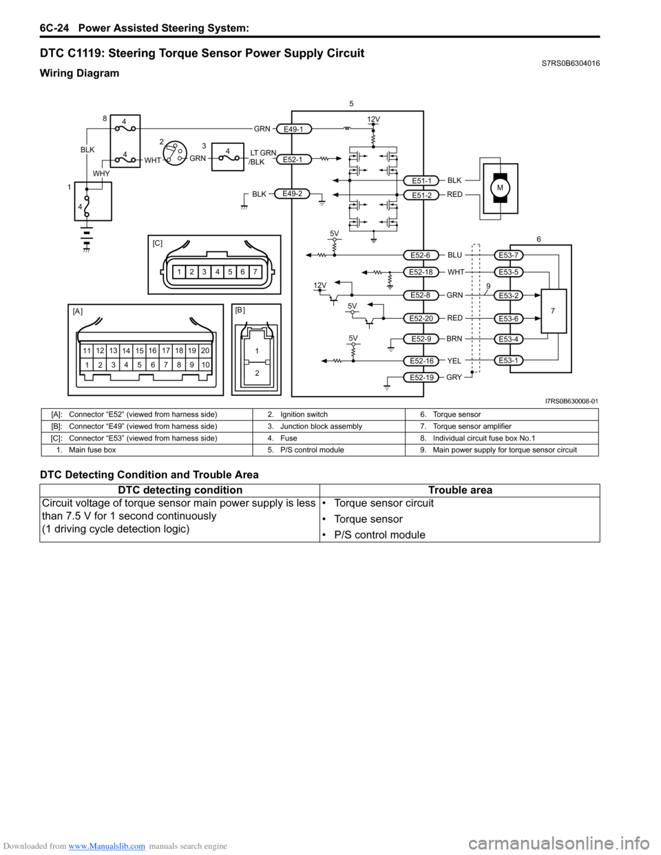
DTC C1119: Steering Torque Sensor Power Supply CircuitS7RS0B6304016
Wiring Diagram
DTC Detecting Condition and Trouble Area
M
5V
BLK
RED
WHT BLU
GRN
BRN YEL
E51-1
E51-2
E52-18
E53-5
E53-7
E52-6
E52-8
E53-2
E52-9
E52-16
E52-19
GRY
5
67
12V
5V
5V
12V
REDE52-20E53-6
E53-4
E53-1
9
[A ]
12 3
4 5 67
89
11
10
12 13
141516
17 18 19 20
1
2
[B ]
[C ]
7654321
LT GRN
/BLKE52-1 E49-1
GRNGRNWHTBLK
WHY
8
3
4
4
4
4
1 2
E49-2BLK
I7RS0B630008-01
[A]: Connector “E52” (viewed from harness side)
2. Ignition switch6. Torque sensor
[B]: Connector “E49” (viewed from harness side) 3. Junction block assembly7. Torque sensor amplifier
[C]: Connector “E53” (viewed from harness si de)4. Fuse 8. Individual circuit fuse box No.1
1. Main fuse box 5. P/S control module9. Main power supply for torque sensor circuit
DTC detecting condition Trouble area
Circuit voltage of torque sensor main power supply is less
than 7.5 V for 1 second continuously
(1 driving cycle detection logic) • Torque sensor circuit
• Torque sensor
• P/S control module
Page 907 of 1496
Downloaded from www.Manualslib.com manuals search engine Power Assisted Steering System: 6C-25
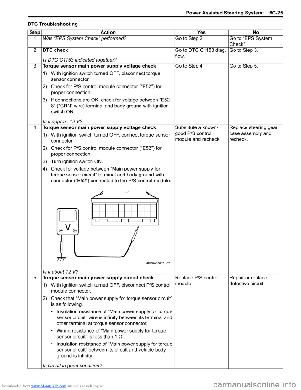
DTC TroubleshootingStep Action Yes No 1 Was “EPS System Check” performed? Go to Step 2. Go to “EPS System
Check”.
2 DTC check
Is DTC C1153 indicated together? Go to DTC C1153 diag.
flow.
Go to Step 3.
3 Torque sensor main power supply voltage check
1) With ignition switch turned OFF, disconnect torque
sensor connector.
2) Check for P/S control module connector (“E52”) for proper connection.
3) If connections are OK, check for voltage between “E52- 8” (“GRN” wire) terminal and body ground with ignition
switch ON.
Is it approx. 12 V? Go to Step 4. Go to Step 5.
4 Torque sensor main power supply voltage check
1) With ignition switch turned OFF, connect torque sensor
connector.
2) Check for P/S control module connector (“E52”) for proper connection.
3) Turn ignition switch ON.
4) Check for voltage between “Main power supply for torque sensor circuit” terminal and body ground with
connector (“E52”) connected to the P/S control module.
Is it about 12 V? Substitute a known-
good P/S control
module and recheck.
Replace steering gear
case assembly and
recheck.
5 Torque sensor main power supply circuit check
1) With ignition switch turned OFF, disconnect P/S control
module connector.
2) Check that “Main power supply for torque sensor circuit” is as following.
• Insulation resistance of “Main power supply for torque sensor circuit” wire is infinity between its terminal and
other terminal at torque sensor connector.
• Wiring resistance of “Main power supply for torque sensor circuit” is less than 1 Ω .
• Insulation resistance of “Main power supply for torque sensor circuit” between its circuit and vehicle body
ground is infinity.
Is circuit in good condition? Replace P/S control
module.
Repair or replace
defective circuit.
8
E52
I4RS0A630021-02
Page 908 of 1496
Downloaded from www.Manualslib.com manuals search engine 6C-26 Power Assisted Steering System:
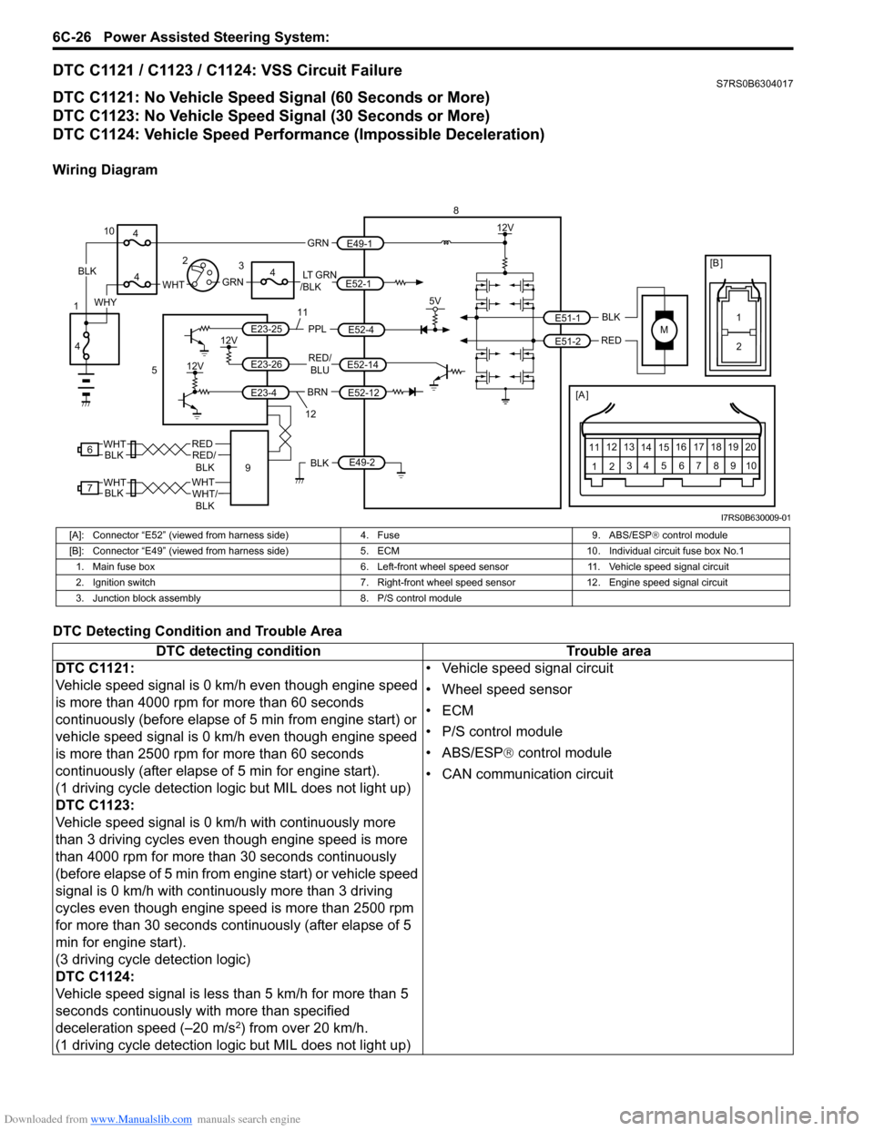
DTC C1121 / C1123 / C1124: VSS Circuit FailureS7RS0B6304017
DTC C1121: No Vehicle Speed Signal (60 Seconds or More)
DTC C1123: No Vehicle Speed Signal (30 Seconds or More)
DTC C1124: Vehicle Speed Performance (Impossible Deceleration)
Wiring Diagram
DTC Detecting Condition and Trouble Area
M
BRNRED/
BLU
BLK
RED
E52-14
E52-12
E23-4
E23-26
E23-25 E51-1
E51-2
[A ]
12
3
4 5 67
89
11
10
12 13
141516
17 18 19 20
5V
PPL
E52-4
8
5
12V
E49-2BLK
12V
12V
6REDRED/ BLKWHT
7WHTWHT/BLKWHTBLK BLK
111
2
[B ]
9
LT GRN
/BLKE52-1 E49-1
GRNGRNWHTBLK
WHY
10
3
4
4
4
4
1 2
12
I7RS0B630009-01
[A]: Connector “E52” (viewed from harness side)
4. Fuse9. ABS/ESP® control module
[B]: Connector “E49” (viewed from harness si de)5. ECM 10. Individual circuit fuse box No.1
1. Main fuse box 6. Left-front wheel speed sensor11. Vehicle speed signal circuit
2. Ignition switch 7. Right-front wheel speed sensor 12. Engine speed signal circuit
3. Junction block assembly 8. P/S control module
DTC detecting condition Trouble area
DTC C1121:
Vehicle speed signal is 0 km/h even though engine speed
is more than 4000 rpm for more than 60 seconds
continuously (before elapse of 5 min from engine start) or
vehicle speed signal is 0 km/h even though engine speed
is more than 2500 rpm for more than 60 seconds
continuously (after elapse of 5 min for engine start).
(1 driving cycle detection logic but MIL does not light up)
DTC C1123:
Vehicle speed signal is 0 km/h with continuously more
than 3 driving cycles even though engine speed is more
than 4000 rpm for more than 30 seconds continuously
(before elapse of 5 min from engine start) or vehicle speed
signal is 0 km/h with continuously more than 3 driving
cycles even though engine speed is more than 2500 rpm
for more than 30 seconds continuously (after elapse of 5
min for engine start).
(3 driving cycle detection logic)
DTC C1124:
Vehicle speed signal is less than 5 km/h for more than 5
seconds continuously with more than specified
deceleration speed (–20 m/s
2) from over 20 km/h.
(1 driving cycle detection logic but MIL does not light up) • Vehicle speed signal circuit
• Wheel speed sensor
•ECM
• P/S control module
• ABS/ESP®
control module
• CAN communication circuit
Page 909 of 1496
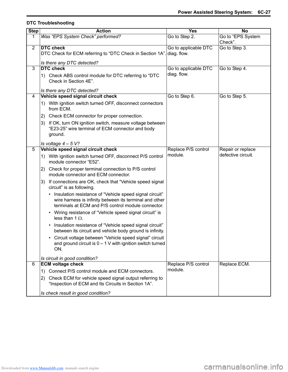
Downloaded from www.Manualslib.com manuals search engine Power Assisted Steering System: 6C-27
DTC TroubleshootingStep Action Yes No 1 Was “EPS System Check” performed? Go to Step 2. Go to “EPS System
Check”.
2 DTC check
DTC Check for ECM referring to “DTC Check in Section 1A”.
Is there any DTC detected? Go to applicable DTC
diag. flow.
Go to Step 3.
3 DTC check
1) Check ABS control module for DTC referring to “DTC
Check in Section 4E”.
Is there any DTC detected? Go to applicable DTC
diag. flow.
Go to Step 4.
4 Vehicle speed signal circuit check
1) With ignition switch turned OFF, disconnect connectors
from ECM.
2) Check ECM connector for proper connection.
3) If OK, turn ON ignition switch, measure voltage between “E23-25” wire terminal of ECM connector and body
ground.
Is voltage 4 – 5 V? Go to Step 6.
Go to Step 5.
5 Vehicle speed signal circuit check
1) With ignition switch turned OFF, disconnect P/S control
module connector “E52”.
2) Check for proper terminal connection to P/S control module connector and ECM connector.
3) If connections are OK, chec k that “Vehicle speed signal
circuit” is as following.
• Insulation resistance of “Vehicle speed signal circuit” wire harness is infinity between its terminal and other
terminals at ECM and P/S control module connector.
• Wiring resistance of “Vehicle speed signal circuit” is less than 1 Ω.
• Insulation resistance of “Vehicle speed signal circuit” between its circuit and vehicle body ground is infinity.
• Circuit voltage between “Vehicle speed signal” circuit and ground circuit is 0 – 1 V with ignition switch turned
ON.
Is circuit in good condition? Replace P/S control
module.
Repair or replace
defective circuit.
6 ECM voltage check
1) Connect P/S control mo dule and ECM connectors.
2) Check ECM for vehicle speed signal output referring to “Inspection of ECM and Its Circuits in Section 1A”.
Is check result in good condition? Replace P/S control
module.
Replace ECM.
Page 910 of 1496
Downloaded from www.Manualslib.com manuals search engine 6C-28 Power Assisted Steering System:
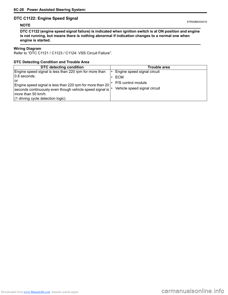
DTC C1122: Engine Speed SignalS7RS0B6304018
NOTE
DTC C1122 (engine speed signal failure) is indicated when ignition switch is at ON position and engine
is not running, but means there is nothing abnormal if indication changes to a normal one when
engine is started.
Wiring Diagram
Refer to “DTC C1121 / C1123 / C1124: VSS Circuit Failure”.
DTC Detecting Condition and Trouble Area DTC detecting condition Trouble area
Engine speed signal is less than 220 rpm for more than
0.8 seconds.
or
Engine speed signal is less than 220 rpm for more than 20
seconds continuously even though vehicle speed signal is
more than 50 km/h.
(1 driving cycle detection logic) • Engine speed signal circuit
•ECM
• P/S control module
• Vehicle speed signal circuit