SUZUKI SWIFT 2017 5.G Owners Manual
Manufacturer: SUZUKI, Model Year: 2017, Model line: SWIFT, Model: SUZUKI SWIFT 2017 5.GPages: 336, PDF Size: 6.24 MB
Page 211 of 336
7-20
INSPECTION AND MAINTENANCE
74LH0-74E
Temporary Spare Tire (if equipped)Your vehicle comes equipped with the tem-
porary spare tire. It is only intended for
temporary emergency use, until the con-
ventional tire can be repaired or replaced.
The inflation pressure of the temporary
spare tire should be checked at least
monthly. At the same time, check that the
tire is stored securely. If it is not, tighten it.
Note that two or more temporary spare
tires should not be used on one vehicle
simultaneously.
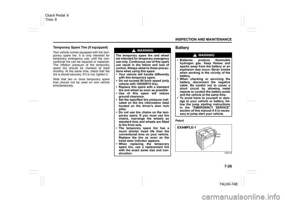
BatteryPetrol
54G118
WA R N I N G
The temporary spare tire and wheel
are intended for temporary emergency
use only. Continuous use of this spare
can result in tire failure and loss of
control. Always observe these precau-
tions when using this spare: Your vehicle will handle differently
with this temporary spare.
Do not exceed 80 km/h speed (only
vehicle with 185/65R15 tire).
Replace this spare with a standard
tire and wheel as soon as possible.
Use of this spare will reduce
ground clearance.
Set the specified tire pressure indi-
cated on the tire information label
located on the driver’s door lock
pillar.
Do not use tire chains on the tem-
porary spare. If you must use tire
chains, rearrange the wheels so
standard tires and wheels are fitted
to the front axle.
The temporary spare tire has a
much shorter tread life than the
conventional tires on your vehicle.
Replace the tire as soon as the
tread wear indicator appears.
When replacing the temporary
spare tire, use a replacement tire
with the exact same size and con-
struction.
WA R N I N G
Batteries produce flammable
hydrogen gas. Keep flames and
sparks away from the battery or an
explosion may occur. Never smoke
when working in the vicinity of the
battery.
When checking or servicing the
battery, disconnect the negative
cable. Be careful not to cause a
short circuit by allowing metal
objects to contact the battery posts
and the vehicle at the same time.
To avoid harm to yourself or dam-
age to your vehicle or battery, fol-
low the jump starting instructions
in the “EMERGENCY SERVICE”
section of this manual if it is neces-
sary to jump start your vehicle.EXAMPLE-1
Clutch Pedal: 6
Tires: 6
Page 212 of 336
7-21INSPECTION AND MAINTENANCE
74LH0-74E
Diesel
The level of the battery solution must be
kept between the “Max” and the “Min” level
lines at all times. If the level is found to be
below the “Min” level line, add distilled
water to bring level between “Max” and
“Min”. You should, however, periodically
check the battery, battery terminals and
battery hold-down bracket for corrosion.
Remove corrosion using a stiff brush and
ammonia mixed with water, or baking soda
mixed with water. After removing corrosion,
rinse with clean water.
If your vehicle is not going to be driven for
a month or longer, disconnect the cable
from the negative terminal of the battery to
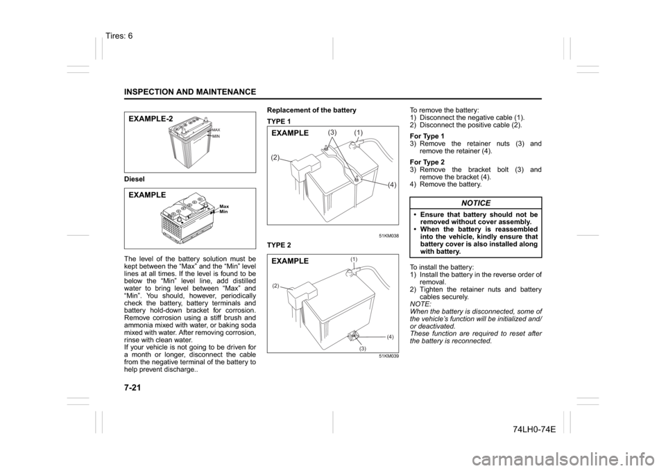
help prevent discharge..Replacement of the battery
TYPE 1
51KM038
TYPE 2
51KM039
To remove the battery:
1) Disconnect the negative cable (1).
2) Disconnect the positive cable (2).
For Type 1
3) Remove the retainer nuts (3) and
remove the retainer (4).
For Type 2
3) Remove the bracket bolt (3) and
remove the bracket (4).
4) Remove the battery.
To install the battery:
1) Install the battery in the reverse order of
removal.
2) Tighten the retainer nuts and battery
cables securely.
NOTE:
When the battery is disconnected, some of
the vehicle’s function will be initialized and/
or deactivated.
These function are required to reset after
the battery is reconnected.
EXAMPLE-2
Max
Min
EXAMPLE
(1)
(2)
(3)
(4)
EXAMPLE
(1)
(2)
(3)
(4)
EXAMPLE
NOTICE
Ensure that battery should not be
removed without cover assembly.
When the battery is reassembled
into the vehicle, kindly ensure that
battery cover is also installed along
with battery.
Tires: 6
Page 213 of 336
7-22
INSPECTION AND MAINTENANCE
74LH0-74E
FusesYour vehicle has three types of fuses, as
described below:
Main fuse
The main fuse takes current directly from
the battery.
Primary fuses
These fuses are between the main fuse
and individual fuses, and are for electrical
load groups.
Individual fuses
These fuses are for individual electrical cir-
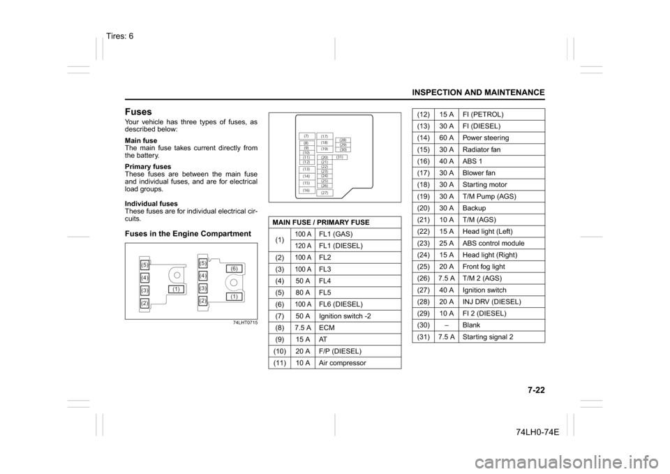
cuits.Fuses in the Engine Compartment
74LHT0715
(5)
(3) (4)
(2)(1)(5)
(4)
(3)
(2)(1) (6)
MAIN FUSE / PRIMARY FUSE
(1)
100 A
FL1 (GAS)
120 A
FL1 (DIESEL)
(2)
100 A
FL2
(3)
100 A
FL3
(4) 50 A FL4
(5) 80 A FL5
(6)
100 A
FL6 (DIESEL)
(7) 50 A Ignition switch -2
(8) 7.5 A ECM
(9) 15 A AT
(10) 20 A F/P (DIESEL)
(11) 10 A Air compressor
(7)
(8)(9)
(10)
(11)
(12)
(13)
(14)
(15)
(16)(17)
(18)
(20) (19)
(21)
(22)
(23)
(25) (24)
(26)
(27)(28)
(29)
(30)
(31)
(12) 15 A FI (PETROL)
(13) 30 A FI (DIESEL)
(14) 60 A Power steering
(15) 30 A Radiator fan
(16) 40 A ABS 1
(17) 30 A Blower fan
(18) 30 A Starting motor
(19) 30 A T/M Pump (AGS)
(20) 30 A Backup
(21) 10 A T/M (AGS)
(22) 15 A Head light (Left)
(23) 25 A ABS control module
(24) 15 A Head light (Right)
(25) 20 A Front fog light
(26) 7.5 A T/M 2 (AGS)
(27) 40 A Ignition switch
(28) 20 A INJ DRV (DIESEL)
(29) 10 A FI 2 (DIESEL)
(30)
Page 214 of 336
7-23INSPECTION AND MAINTENANCE
74LH0-74E
The main fuse, primary fuses and some of
the individual fuses are located in the
engine compartment. If the main fuse
blows, no electrical component will func-
tion. If a primary fuse blows, no electrical
component in the corresponding load
group will function. When replacing the
main fuse, a primary fuse or an individual
fuse, use a MARUTI genuine replacement.
To remove a fuse, use the fuse puller pro-
vided in the fuse box. The amperage of
each fuse is shown in the back of the fuse
box cover.
60G111
NOTE:
Make sure that the fuse box always carries
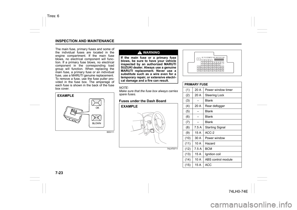
spare fuses.Fuses under the Dash Board
74LHT0711
EXAMPLE
BLOWNOK
WA R N I N G
If the main fuse or a primary fuse
blows, be sure to have your vehicle
inspected by an authorized MARUTI
SUZUKI dealer. Always use a genuine
MARUTI replacement. Never use a
substitute such as a wire even for a
temporary repair, or extensive electri-
cal damage and a fire can result.EXAMPLE
PRIMARY FUSE
(1) 20 A Power window timer
(2) 20 A Steering Lock
(3) – Blank
(4) 20 A Rear defogger
(5) – Blank
(6) – Blank
(7) – Blank
(8) 7.5 A Starting Signal
(9) 15 A ACC-2
(10) 30 A Power window
(11) 10 A Hazard
(12) 7.5 A BCM
(13) 15 A Ignition coil
(14) 10 A ABS control module
(15) 15 A ACC
(3)
(12)(10)
(13)
(36) (1) (2) (4)
(5)(6)
(7) (8)(9)
(11) (14) (15)
(16) (17) (18) (19) (20) (21) (22)
(23) (24) (25) (26) (27) (28) (29)
(30) (31) (32) (33) (34) (35)
Tires: 6
Page 215 of 336
7-24
INSPECTION AND MAINTENANCE
74LH0-74E
81A283
Bulb Replacement
(16) – Blank
(17) 15 A Horn
(18) 10 A Stop light
(19) 10 A Air bag
(20) 10 A Back-up light
(21) 15 A Rear wiper / Washer
(22) 25 A Front wiper
(23) 7.5 A Dome light
(24) – Blank
(25) 7.5 A RR fog lamp
(26) – Blank
(27) 7.5 A Ignition-1 signal
(28) 15 A Radio 2
(29) – Blank
(30) 15 A Radio
(31) 10 A Tail lamp
(32) 20 A D/L
(33) – Blank
(34) 10 A Meter
(35) 7.5 A Ignition-2 signal
(36) – Blank
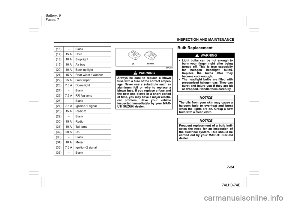
WA R N I N G
Always be sure to replace a blown
fuse with a fuse of the correct amper-
age. Never use a substitute such as
aluminum foil or wire to replace a
blown fuse. If you replace a fuse and
the new one blows in a short period
of time, you may have a major electri-
cal problem. Have your vehicle
inspected immediately by your MAR-
UTI SUZUKI dealer.
OK
BLOWN
WA R N I N G
Light bulbs can be hot enough to
burn your finger right after being
turned off. This is true especially
for halogen headlight bulbs.
Replace the bulbs after they
become cool enough.
The headlight bulbs are filled with
pressurized halogen gas. They can
burst and injure you if they are hit
or dropped. Handle them carefully.
NOTICE
The oils from your skin may cause a
halogen bulb to overheat and burst
when the lights are on. Grasp a new
bulb with a clean cloth.
NOTICE
Frequent replacement of a bulb indi-
cates the need for an inspection of
the electrical system. This should be
carried out by your MARUTI SUZUKI
dealer.
Battery: 9
Fuses: 7
Page 216 of 336
7-25INSPECTION AND MAINTENANCE
74LH0-74E
Interior LightFront
60G114
Center
60G115
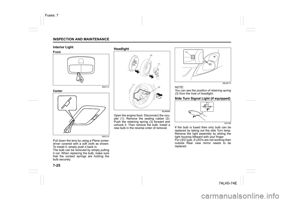
Pull down the lens by using a Plane screw-
driver covered with a soft cloth as shown.
To install it, simply push it back in.
The bulb can be removed by simply pulling
it out. When replacing the bulb, make sure
that the contact springs are holding the
bulb securely.
Headlight
80JM069
Open the engine food. Disconnect the cou-
pler (1). Remove the sealing rubber (2).
Push the retaining spring (3) forward and
unhook it. Then remove the bulb. Install a
new bulb in the reverse order of removal.
68LM713
NOTE:
You can see the position of retaining spring
(3) from the hole of headlight.Side Turn Signal Light (if equipped)
64J195
If the bulb is fused then only bulb can be
replaced by taking out the side Turn lamp.
Remove the light assembly by sliding the
light housing leftward with your finger.
For LED type, if LED’s are not working then
outside Rear view mirror needs to be
replaced.
(2)
(1)(3)
(3)
Fuses: 7
Page 217 of 336
7-26
INSPECTION AND MAINTENANCE
74LH0-74E
Other General LightsBulb holder
54G123
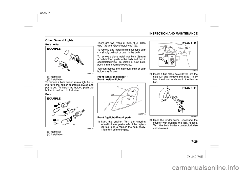
(1) Removal
(2) Installation
To remove a bulb holder from a light hous-
ing, turn the holder counterclockwise and
pull it out. To install the holder, push the
holder in and turn it clockwise.
Bulb
54G124
(3) Removal
(4) InstallationThere are two types of bulb, “Full glass
type” (1) and “Glass/metal type” (2).
To remove and install a full glass type bulb
(1), simply pull out or push in the bulb.
To remove a glass metal type bulb (2) from
a bulb holder, push in the bulb and turn it
counterclockwise. To install a new bulb,
push it in and turn it clockwise.
You can access the individual bulb or bulb
holders as follows.
Front turn signal light (1)
Front position light (2)
68LM714
Front fog light (if equipped)
1) Start the engine. Turn the steering
wheel to the opposite side of the replac-
ing fog light to replace the bulb easily.
Then turn off the engine.
68LM715
2) Insert a flat blade screwdriver into the
hole (2) and remove the clips (1) by
twist the driver as shown in the illustra-
tion.
80JM071
3) Open the fender cover. Disconnect the
coupler with pushing the lock release.
Turn the bulb holder counterclockwise
and remove it.
(1)
(1) (2)(2)
EXAMPLE
(1)
(2) (3)
(4)
EXAMPLE
EXAMPLEEXAMPLE
Fuses: 7
Page 218 of 336
7-27INSPECTION AND MAINTENANCE
74LH0-74E
Rear combination light
(tail, stop, turn signal, etc.)
68LM704
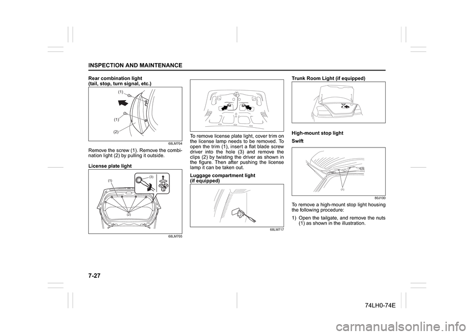
Remove the screw (1). Remove the combi-
nation light (2) by pulling it outside.
License plate light
68LM705
To remove license plate light, cover trim on
the license lamp needs to be removed. To
open the trim (1), insert a flat blade screw
driver into the hole (3) and remove the
clips (2) by twisting the driver as shown in
the figure. Then after pushing the license
lamp it can be taken out.
Luggage compartment light
(if equipped)
68LM717
Trunk Room Light (if equipped)
High-mount stop light
Swift
80J100
To remove a high-mount stop light housing
the following procedure:
1) Open the tailgate, and remove the nuts
(1) as shown in the illustration.
(1)(1)
(2)
(2)(3)
(1)
Page 219 of 336
7-28
INSPECTION AND MAINTENANCE
74LH0-74E
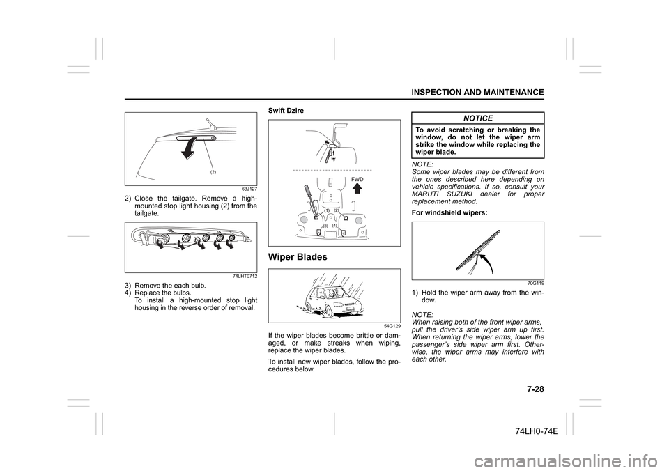
63J127
2) Close the tailgate. Remove a high-
mounted stop light housing (2) from the
tailgate.
74LHT0712
3) Remove the each bulb.
4) Replace the bulbs.
To install a high-mounted stop light
housing in the reverse order of removal.Swift Dzire
Wiper Blades
54G129
If the wiper blades become brittle or dam-
aged, or make streaks when wiping,
replace the wiper blades.
To install new wiper blades, follow the pro-
cedures below.NOTE:
Some wiper blades may be different from
the ones described here depending on
vehicle specifications. If so, consult your
MARUTI SUZUKI dealer for proper
replacement method.
For windshield wipers:
70G119
1) Hold the wiper arm away from the win-
dow.
NOTE:
When raising both of the front wiper arms,
pull the driver’s side wiper arm up first.
When returning the wiper arms, lower the
passenger’s side wiper arm first. Other-
wise, the wiper arms may interfere with
each other.
(2)
NOTICE
To avoid scratching or breaking the
window, do not let the wiper arm
strike the window while replacing the
wiper blade.
Page 220 of 336
7-29INSPECTION AND MAINTENANCE
74LH0-74E
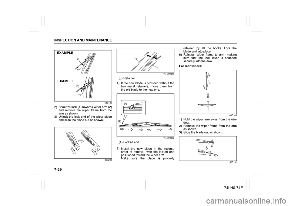
54G130
2) Squeeze lock (1) towards wiper arm (2)
and remove the wiper frame from the
arm as shown.
3) Unlock the lock end of the wiper blade
and slide the blade out as shown.
60A26071LMT0708
(3) Retainer
4) If the new blade is provided without the
two metal retainers, move them from
the old blade to the new one.
71LMT0707
(4) Locked end
5) Install the new blade in the reverse
order of removal, with the locked end
positioned toward the wiper arm.
Make sure the blade is properlyretained by all the hooks. Lock the
blade end into place.
6) Reinstall wiper frame to arm, making
sure that the lock lever is snapped
securely into the arm.
For rear wipers:
80G146
1) Hold the wiper arm away from the win-
dow.
2) Remove the wiper frame from the arm
as shown.
3) Slide the blade out as shown.
65D151
EXAMPLE
EXAMPLE
(3)
(3)
(4)(4)