Ignition system SUZUKI SX4 2006 1.G Service Workshop Manual
[x] Cancel search | Manufacturer: SUZUKI, Model Year: 2006, Model line: SX4, Model: SUZUKI SX4 2006 1.GPages: 1556, PDF Size: 37.31 MB
Page 408 of 1556
Downloaded from www.Manualslib.com manuals search engine 1I-3 Starting System:
Cranking System TestS6RW0D1904002
CAUTION!
Each test must be performed within 3 – 5
seconds to avoid coil from burning.
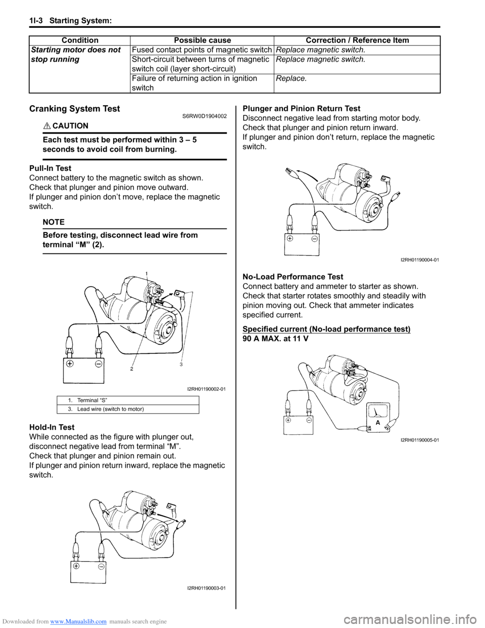
Pull-In Test
Connect battery to the magnetic switch as shown.
Check that plunger and pinion move outward.
If plunger and pinion don’t move, replace the magnetic
switch.
NOTE
Before testing, disconnect lead wire from
terminal “M” (2).
Hold-In Test
While connected as the figure with plunger out,
disconnect negative lead from terminal “M”.
Check that plunger and pinion remain out.
If plunger and pinion return inward, replace the magnetic
switch.Plunger and Pinion Return Test
Disconnect negative lead from starting motor body.
Check that plunger and pinion return inward.
If plunger and pinion don’t return, replace the magnetic
switch.
No-Load Performance Test
Connect battery and ammeter to starter as shown.
Check that starter rotates smoothly and steadily with
pinion moving out. Check that ammeter indicates
specified current.
Specified current (No-load performance test)
90 A MAX. at 11 V Starting motor does not
stop runningFused contact points of magnetic switchReplace magnetic switch.
Short-circuit between turns of magnetic
switch coil (layer short-circuit)Replace magnetic switch.
Failure of returning action in ignition
switchReplace. Condition Possible cause Correction / Reference Item
1. Terminal “S”
3. Lead wire (switch to motor)
I2RH01190002-01
I2RH01190003-01
I2RH01190004-01
I2RH01190005-01
Page 417 of 1556
Downloaded from www.Manualslib.com manuals search engine Charging System: 1J-3
Generator DescriptionS6RW0D1A01002
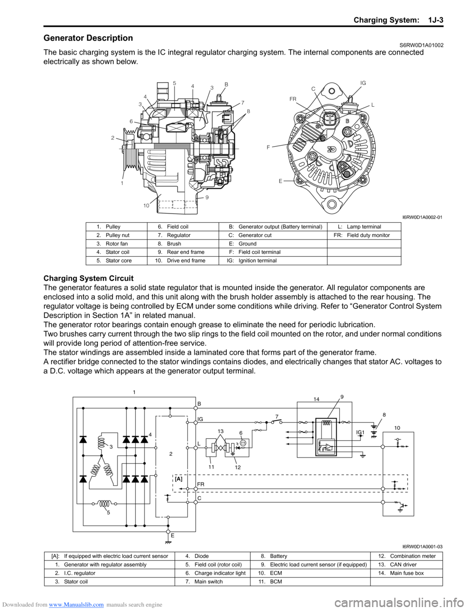
The basic charging system is the IC integral regulator charging system. The internal components are connected
electrically as shown below.
Charging System Circuit
The generator features a solid state regulator that is mounted inside the generator. All regulator components are
enclosed into a solid mold, and this unit along with the brush holder assembly is attached to the rear housing. The
regulator voltage is being controlled by ECM under some conditions while driving. Refer to “Generator Control System
Description in Section 1A” in related manual.
The generator rotor bearings contain enough grease to eliminate the need for periodic lubrication.
Two brushes carry current through the two slip rings to the field coil mounted on the rotor, and under normal conditions
will provide long period of attention-free service.
The stator windings are assembled inside a laminated core that forms part of the generator frame.
A rectifier bridge connected to the stator windings contains diodes, and electrically changes that stator AC. voltages to
a D.C. voltage which appears at the generator output terminal.
1 26345
4
3B
7
8
9
10E FFRCIG
L
I6RW0D1A0002-01
1. Pulley 6. Field coil B: Generator output (Battery terminal) L: Lamp terminal
2. Pulley nut 7. Regulator C: Generator cut FR: Field duty monitor
3. Rotor fan 8. Brush E: Ground
4. Stator coil 9. Rear end frame F: Field coil terminal
5. Stator core 10. Drive end frame IG: Ignition terminal
B
IG
L
C
E
7
2 4
3
5
FR
610
11
12 13 1
[A]
IG1 9
14
8
I6RW0D1A0001-03
[A]: If equipped with electric load current sensor 4. Diode 8. Battery 12. Combination meter
1. Generator with regulator assembly 5. Field coil (rotor coil) 9. Electric load current sensor (if equipped) 13. CAN driver
2. I.C. regulator 6. Charge indicator light 10. ECM 14. Main fuse box
3. Stator coil 7. Main switch 11. BCM
Page 418 of 1556
Downloaded from www.Manualslib.com manuals search engine 1J-4 Charging System:
Diagnostic Information and Procedures
Battery InspectionS6RW0D1A04001
Common Causes of Failure
A battery is not designed to last indefinitely; however,
with proper care, it will provide many years of service. If
the battery performs satisfactorily during test buy fails to
operate properly for no apparent reason, the following
are some factors that may point to the cause of trouble:
• Accessories left on overnight or for an extended
period without the generator operating.
• Slow average driving speed for short periods.
• Electrical load exceeding generator output particularly
with addition of aftermarket equipment.
• Defects in charging system such as high resistance,
slipping drive belt, loose generator output terminal,
faulty generator or voltage regulator. Refer to
“Generator Symptom Diagnosis”.
• Battery abuse, including failure to keep battery cable
terminals clean and tight or loose battery hold down.
• Mechanical problems in electrical system such as
shorted or pinched wires.
Visual Inspection
Check for obvious damage, such as cracked or broken
case or cover, that could permit loss of electrolyte. If
obvious damage is noted, replace battery. Determine
cause of damage and correct as needed.
Generator Symptom DiagnosisS6RW0D1A04002
CAUTION!
• Do not mistake polarities of “IG” terminal
and “L” terminal.
• Do not create short circuit between “IG”
and “L” terminals. Always connect these
terminals through a lamp.
• Do not connect any load between “L” and
“E” terminals.
• When connecting charger or booster
battery to vehicle battery, refer to “Jump
Starting in Case of Emergency”.
Trouble in charging system will show up as one or more
of the following conditions:
1) Faulty indicator lamp operation.
2) An undercharged battery as evidenced by slow
cranking or indicator dark.
3) An overcharged battery as evidenced by excessive
spewing of electrolyte from vents.
Noise from generator may be caused by loose drive
pulley, loose mounting bolts, worn or dirty bearings,
defective diode, or defective stator.
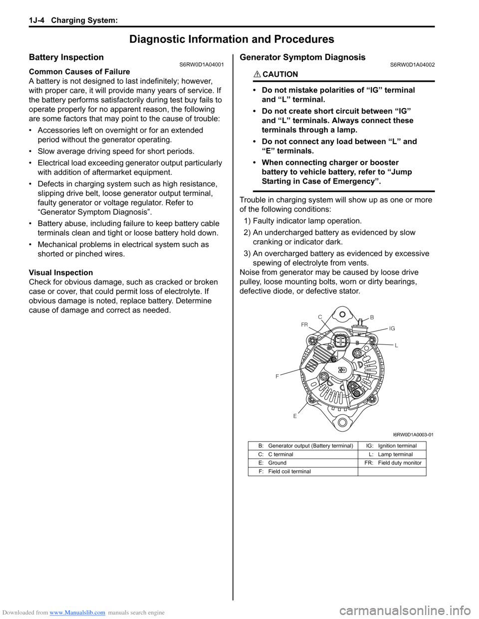
B: Generator output (Battery terminal) IG: Ignition terminal
C: C terminal L: Lamp terminal
E: Ground FR: Field duty monitor
F: Field coil terminal
E FFRC
B
IG
L
I6RW0D1A0003-01
Page 419 of 1556
Downloaded from www.Manualslib.com manuals search engine Charging System: 1J-5
Charging Indicator Lamp Operation
Generator Test (Undercharged Battery Check)S6RW0D1A04003
This condition, as evidenced by slow cranking or low
specific gravity can be caused by one or more of the
following conditions even though indicator lamp may be
operating normal. The following procedure also applies
to cars with voltmeter and ammeter.
• Make sure that undercharged condition has not been
caused by accessories left on for extended period of
time.
• Check drive belt for proper tension.
• If battery defect is suspected, refer to “Battery
Description”.
• Inspect wiring for defects. Check all connections for
tightness and cleanliness, battery cable connections
at battery, starting motor and ignition ground cable.
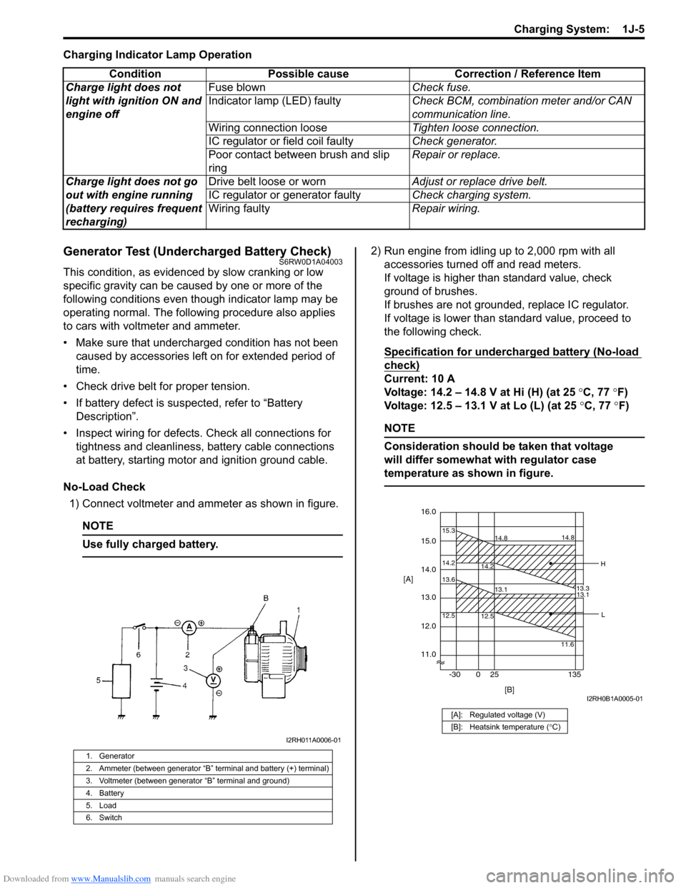
No-Load Check
1) Connect voltmeter and ammeter as shown in figure.
NOTE
Use fully charged battery.
2) Run engine from idling up to 2,000 rpm with all
accessories turned off and read meters.
If voltage is higher than standard value, check
ground of brushes.
If brushes are not grounded, replace IC regulator.
If voltage is lower than standard value, proceed to
the following check.
Specification for undercharged battery (No-load
check)
Current: 10 A
Voltage: 14.2 – 14.8 V at Hi (H) (at 25 °C, 77 °F)
Voltage: 12.5 – 13.1 V at Lo (L) (at 25 °C, 77 °F)
NOTE
Consideration should be taken that voltage
will differ somewhat with regulator case
temperature as shown in figure.
Condition Possible cause Correction / Reference Item
Charge light does not
light with ignition ON and
engine offFuse blownCheck fuse.
Indicator lamp (LED) faultyCheck BCM, combination meter and/or CAN
communication line.
Wiring connection looseTighten loose connection.
IC regulator or field coil faultyCheck generator.
Poor contact between brush and slip
ringRepair or replace.
Charge light does not go
out with engine running
(battery requires frequent
recharging)Drive belt loose or wornAdjust or replace drive belt.
IC regulator or generator faultyCheck charging system.
Wiring faultyRepair wiring.
1. Generator
2. Ammeter (between generator “B” terminal and battery (+) terminal)
3. Voltmeter (between generator “B” terminal and ground)
4. Battery
5. Load
6. Switch
I2RH011A0006-01
[A]: Regulated voltage (V)
[B]: Heatsink temperature (°C)
16.0
12.0
14.2 15.3
14.8
14.2
13.3 14.8
15.0
11.0 14.0
13.0 [A]
12.5 13.6
13.1
12.5
11.613.1
[B] -30 0 25 135
H
L
I2RH0B1A0005-01
Page 421 of 1556
Downloaded from www.Manualslib.com manuals search engine Charging System: 1J-7
1) Set parking brake and place automatic transaxle in
PARK (NEUTRAL on manual transaxle). Turn off
ignition, turn off lights and all other electrical loads.
2) Check electrolyte level. If it is below low level line,
add distilled water.
3) Attach end of one jumper cable to positive terminal
of booster battery and the other end of the same
cable to positive terminal of discharged battery. (Use
12-volt battery only to jump start engine).
4) Attach one end of the remaining negative cable to
negative terminal of booster battery, and the other
end to a solid engine ground (such as exhaust
manifold) at least 45 cm (18 in.) away from battery of
vehicle being started.
5) Start engine of vehicle with booster battery and turn
off electrical accessories. Then start engine of the
vehicle with discharged battery.
6) Disconnect jumper cables in the exact reverse order.
With Charging Equipment
CAUTION!
When jump starting engine with charging
equipment, be sure equipment used is 12-
volt and negative ground. Do not use 24-volt
charging equipment. Using such equipment
can cause serious damage to electrical
system or electronic parts.
Battery Dismounting and RemountingS6RW0D1A06002
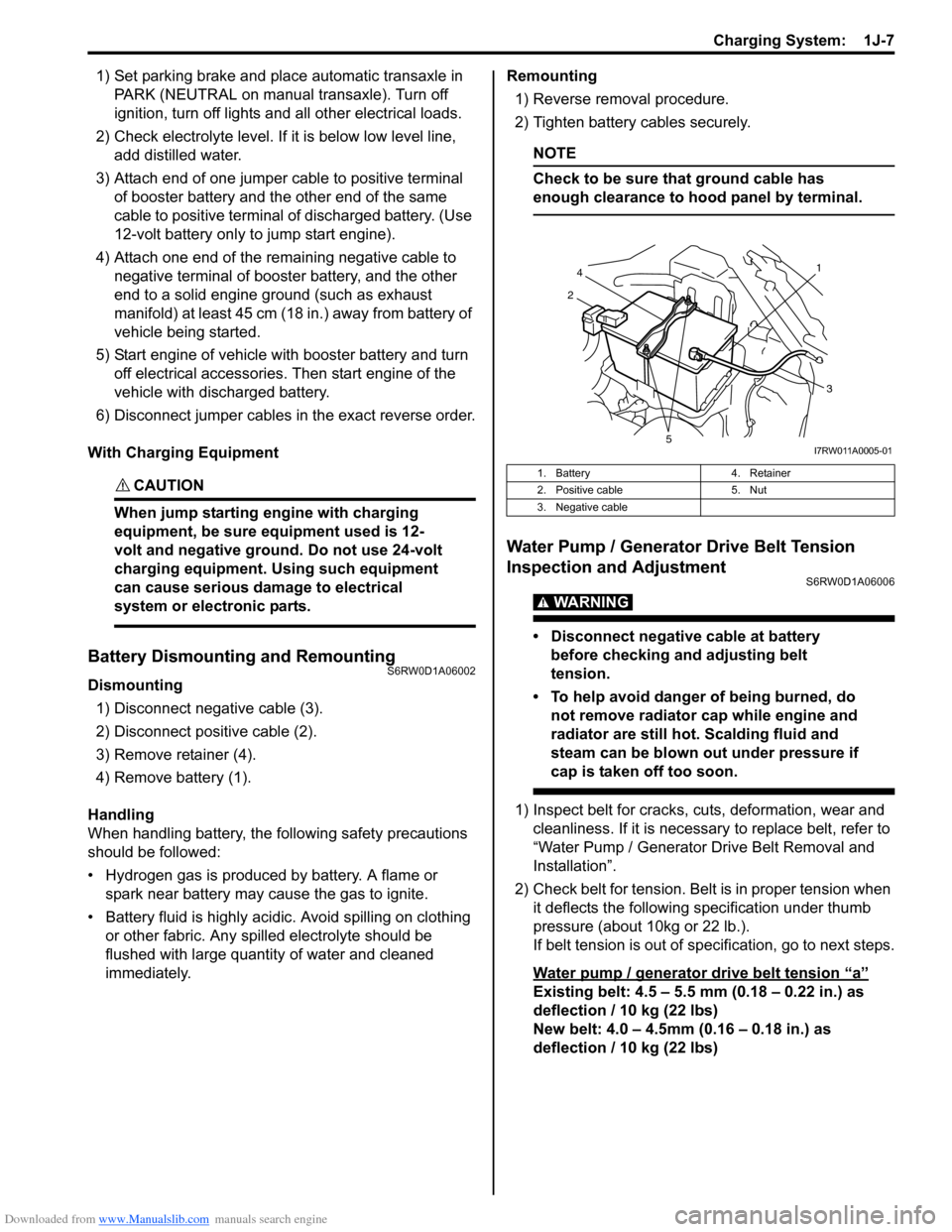
Dismounting
1) Disconnect negative cable (3).
2) Disconnect positive cable (2).
3) Remove retainer (4).
4) Remove battery (1).
Handling
When handling battery, the following safety precautions
should be followed:
• Hydrogen gas is produced by battery. A flame or
spark near battery may cause the gas to ignite.
• Battery fluid is highly acidic. Avoid spilling on clothing
or other fabric. Any spilled electrolyte should be
flushed with large quantity of water and cleaned
immediately.Remounting
1) Reverse removal procedure.
2) Tighten battery cables securely.
NOTE
Check to be sure that ground cable has
enough clearance to hood panel by terminal.
Water Pump / Generator Drive Belt Tension
Inspection and Adjustment
S6RW0D1A06006
WARNING!
• Disconnect negative cable at battery
before checking and adjusting belt
tension.
• To help avoid danger of being burned, do
not remove radiator cap while engine and
radiator are still hot. Scalding fluid and
steam can be blown out under pressure if
cap is taken off too soon.
1) Inspect belt for cracks, cuts, deformation, wear and
cleanliness. If it is necessary to replace belt, refer to
“Water Pump / Generator Drive Belt Removal and
Installation”.
2) Check belt for tension. Belt is in proper tension when
it deflects the following specification under thumb
pressure (about 10kg or 22 lb.).
If belt tension is out of specification, go to next steps.
Water pump / generator drive belt tension
“a”
Existing belt: 4.5 – 5.5 mm (0.18 – 0.22 in.) as
deflection / 10 kg (22 lbs)
New belt: 4.0 – 4.5mm (0.16 – 0.18 in.) as
deflection / 10 kg (22 lbs)
1. Battery 4. Retainer
2. Positive cable 5. Nut
3. Negative cable
21
4
3
5I7RW011A0005-01
Page 474 of 1556
Downloaded from www.Manualslib.com manuals search engine 2D-5 Wheels and Tires:
Repair Instructions
Wheel Discs InspectionS6RW0D2406006
Inspect each wheel disc for dents, distortion and cracks.
A disc in badly damaged condition must be replaced.
Wheel Balance Inspection and AdjustmentS6RW0D2406001
Refer to “Balancing Wheels Description”.
Deposits of mud, etc. must be cleaned from inside of rim.
WARNING!
Stones should be removed from the tread in
order to avoid operator injury during spin
balancing and to obtain good balance.
Each tire should be inspected for any damage, then
balanced according to equipment manufacturer’s
recommendation.
Off-Vehicle Balancing
Most electronic off-vehicle balancers are more accurate
than the on-vehicle spin balancers. They are easy to use
and give a dynamic (two plane) balance. Although they
do not correct for drum or disc unbalance as does on-
vehicle spin balancing, this is overcome by their
accuracy, usually to within 1/8 ounce.
On-Vehicle Balancing
On-vehicle balancing methods vary with equipment and
tool manufacturers. Be sure to follow each
manufacturer’s instructions during balancing operation.
WARNING!
Wheel spin should be limited to 55 km/h (35
mph) as indicated on speedometer.
This limit is necessary because speedometer
only indicates one-half of actual wheel speed
when one drive wheel is spinning and the
other drive wheel is stopped.
Unless care is taken in limiting drive wheel
spin, spinning wheel can reach excessive
speeds. This can result in possible tire
disintegration or differential failure, which
could cause serious personal injury or
extensive vehicle damage.
CAUTION!
For vehicle equipped with ABS, using on-
vehicle balancing method with ignition
switch ON may set malfunction diagnostic
trouble code (DTC) of ABS even when system
is in good condition.
Never turn ignition switch ON while spinning
wheel.
Tire RotationS6RW0D2406002
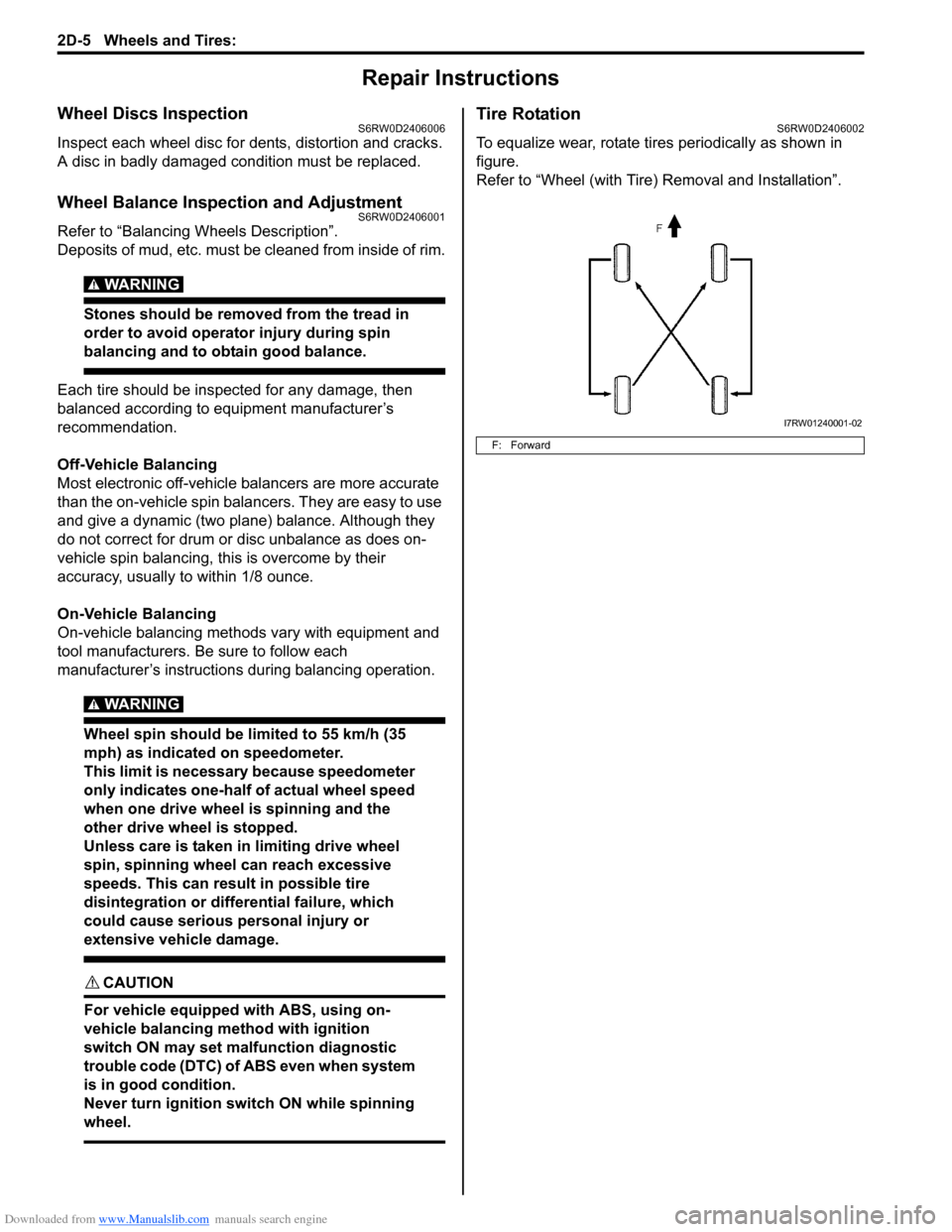
To equalize wear, rotate tires periodically as shown in
figure.
Refer to “Wheel (with Tire) Removal and Installation”.
F: Forward
I7RW01240001-02
Page 477 of 1556
Downloaded from www.Manualslib.com manuals search engine Table of Contents 3- i
3
Section 3
CONTENTS
Driveline / Axle
Precautions ................................................. 3-1
Precautions............................................................. 3-1
Precautions on Driveline / Axle ............................. 3-1
Drive Shaft / Axle ..................................... 3A-1
Front ......................................................................... 3A-1
General Description ............................................. 3A-1
Front Drive Shaft Construction ............................ 3A-1
Component Location ........................................... 3A-1
Front Drive Shaft Assembly Components
Location ............................................................ 3A-1
Diagnostic Information and Procedures ............ 3A-2
Front Drive Shaft Symptom Diagnosis ................ 3A-2
Repair Instructions .............................................. 3A-2
Front Drive Shaft Components ........................... 3A-2
Front Drive Shaft Assembly On-Vehicle
Inspection.......................................................... 3A-3
Front Drive Shaft Assembly Removal and
Installation ......................................................... 3A-3
Front Drive Shaft Disassembly and
Reassembly ...................................................... 3A-4
Center Shaft and Center Bearing Support
Disassembly and Reassembly (If Equipped) .. 3A-12
Specifications..................................................... 3A-13
Tightening Torque Specifications ...................... 3A-13
Special Tools and Equipment ........................... 3A-14
Recommended Service Material ....................... 3A-14
Special Tool ...................................................... 3A-14
Rear ........................................................................ 3A-15
General Description ........................................... 3A-15
Rear Drive Shaft Construction .......................... 3A-15
Repair Instructions ............................................ 3A-15
Rear Drive Shaft Components .......................... 3A-15
Rear Drive Shaft Assembly Removal and
Installation ....................................................... 3A-16
Rear Drive Shaft Disassembly and
Reassembly .................................................... 3A-16
Specifications..................................................... 3A-18
Tightening Torque Specifications ...................... 3A-18
Special Tools and Equipment ........................... 3A-18
Recommended Service Material ....................... 3A-18
Special Tool ...................................................... 3A-18
Differential ................................................ 3B-1
Precautions...........................................................3B-1
Precaution for Rear Differential Oil Leakage....... 3B-1
Precautions in Diagnosing Trouble ..................... 3B-1
General Description .............................................3B-2
Rear Differential Description ............................... 3B-2
Coupling Description ........................................... 3B-2
4WD Control System Components ..................... 3B-3
4WD Control System Description........................ 3B-4
Function of 4WD Control System Component .... 3B-4
4WD Control System Wiring Circuit Diagram...... 3B-5
Terminal Arrangement of 4WD Control
Module .............................................................. 3B-5
Input / Output Signal Table of 4WD Control
Module .............................................................. 3B-6
On-Board Diagnostic System Description ........... 3B-6
CAN Communication System Description........... 3B-7
Diagnostic Information and Procedures ............3B-8
4WD Control System Check ............................... 3B-8
4WD Position Indicator Operation Check.......... 3B-10
4WD Control System Operation Inspection ...... 3B-10
Visual Inspection ............................................... 3B-11
DTC Check........................................................ 3B-11
DTC Clearance ................................................. 3B-11
DTC Table ......................................................... 3B-12
Fail-Safe Table .................................................. 3B-12
Scan Tool Data ................................................. 3B-13
Rear Differential Symptom Diagnosis ............... 3B-14
4WD Control Symptom Diagnosis..................... 3B-14
4WD Position Indicator Does Not Come ON at
Ignition Switch ON but Engine Stops .............. 3B-15
4WD Position Indicator Remains ON Steady
at Ignition Switch ON....................................... 3B-16
DTC C1240: 4WD Control Module Power
Supply Circuit Malfunction............................... 3B-17
DTC C1243: Internal Circuit Malfunction of
4WD Control Module ....................................... 3B-18
DTC C1250: Coupling Air Temperature
Sensor Circuit Open ........................................ 3B-19
DTC C1251: Coupling Air Temperature
Sensor Circuit Short ........................................ 3B-21
DTC C1252: Coupling Assembly Circuit Open .. 3B-22
DTC C1253: Coupling Assembly Circuit Short .. 3B-24
DTC C1254: 2WD/4WD Switch Malfunction ..... 3B-25
DTC U0073: Control Module Communication
Bus Off ............................................................ 3B-27
Page 501 of 1556
Downloaded from www.Manualslib.com manuals search engine Differential: 3B-4
4WD Control System DescriptionS6RW0D3201004
4WD Shift Control
The 4WD control module operates the coupling assembly according to the 2WD/4WD switch operation to the selected
position (2WD, 4WD-auto or 4WD-lock). Also, the 4WD control system has 4WD AUTO indicator and 4WD LOCK
indicator in order to inform the 4WD control system condition.
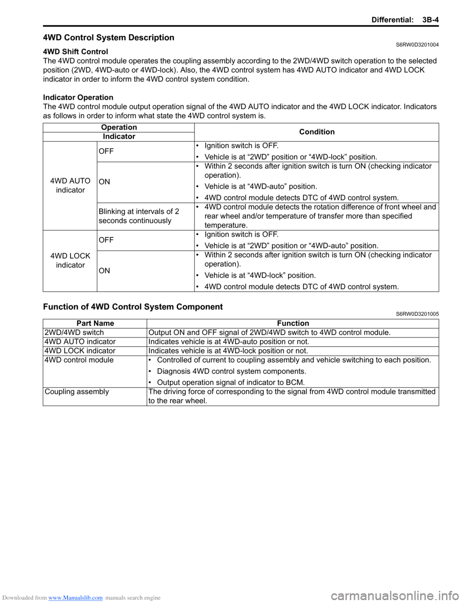
Indicator Operation
The 4WD control module output operation signal of the 4WD AUTO indicator and the 4WD LOCK indicator. Indicators
as follows in order to inform what state the 4WD control system is.
Function of 4WD Control System ComponentS6RW0D3201005
Operation
Condition
Indicator
4WD AUTO
indicatorOFF• Ignition switch is OFF.
• Vehicle is at “2WD” position or “4WD-lock” position.
ON• Within 2 seconds after ignition switch is turn ON (checking indicator
operation).
• Vehicle is at “4WD-auto” position.
• 4WD control module detects DTC of 4WD control system.
Blinking at intervals of 2
seconds continuously• 4WD control module detects the rotation difference of front wheel and
rear wheel and/or temperature of transfer more than specified
temperature.
4WD LOCK
indicatorOFF• Ignition switch is OFF.
• Vehicle is at “2WD” position or “4WD-auto” position.
ON• Within 2 seconds after ignition switch is turn ON (checking indicator
operation).
• Vehicle is at “4WD-lock” position.
• 4WD control module detects DTC of 4WD control system.
Part Name Function
2WD/4WD switch Output ON and OFF signal of 2WD/4WD switch to 4WD control module.
4WD AUTO indicator Indicates vehicle is at 4WD-auto position or not.
4WD LOCK indicator Indicates vehicle is at 4WD-lock position or not.
4WD control module • Controlled of current to coupling assembly and vehicle switching to each position.
• Diagnosis 4WD control system components.
• Output operation signal of indicator to BCM.
Coupling assembly The driving force of corresponding to the signal from 4WD control module transmitted
to the rear wheel.
Page 503 of 1556
Downloaded from www.Manualslib.com manuals search engine Differential: 3B-6
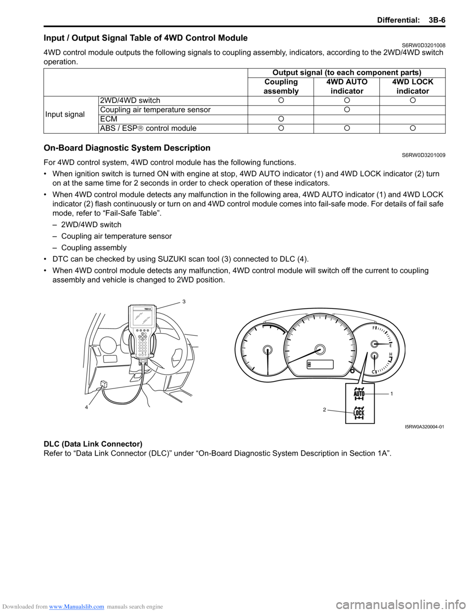
Input / Output Signal Table of 4WD Control ModuleS6RW0D3201008
4WD control module outputs the following signals to coupling assembly, indicators, according to the 2WD/4WD switch
operation.
On-Board Diagnostic System DescriptionS6RW0D3201009
For 4WD control system, 4WD control module has the following functions.
• When ignition switch is turned ON with engine at stop, 4WD AUTO indicator (1) and 4WD LOCK indicator (2) turn
on at the same time for 2 seconds in order to check operation of these indicators.
• When 4WD control module detects any malfunction in the following area, 4WD AUTO indicator (1) and 4WD LOCK
indicator (2) flash continuously or turn on and 4WD control module comes into fail-safe mode. For details of fail safe
mode, refer to “Fail-Safe Table”.
– 2WD/4WD switch
– Coupling air temperature sensor
– Coupling assembly
• DTC can be checked by using SUZUKI scan tool (3) connected to DLC (4).
• When 4WD control module detects any malfunction, 4WD control module will switch off the current to coupling
assembly and vehicle is changed to 2WD position.
DLC (Data Link Connector)
Refer to “Data Link Connector (DLC)” under “On-Board Diagnostic System Description in Section 1A”.Output signal (to each component parts)
Coupling
assembly4WD AUTO
indicator4WD LOCK
indicator
Input signal2WD/4WD switch�{�{�{
Coupling air temperature sensor�{
ECM�{
ABS / ESP® control module�{�{�{
1
2 3
4
I5RW0A320004-01
Page 507 of 1556
Downloaded from www.Manualslib.com manuals search engine Differential: 3B-10
Step 2. DTC check, record and clearance
First, referring to “DTC Check”, check DTC and pending
DTC. If DTC exists, print or write down DTC and then
clear malfunction DTC(s) by referring to “DTC
Clearance”. Malfunction DTC indicates malfunction in
the system but it is not possible to know from it whether
the malfunction is occurring now or it occurred in the
past and normal condition has been restored. In order to
know that, check symptom in question according to Step
5 and then recheck DTC according to Step 6.
Diagnosing a trouble based on the DTC in this step only
or failure to clear the DTC in this step may result in an
faulty diagnosis, trouble diagnosis of a normal circuit or
difficulty in troubleshooting which is otherwise
unnecessary.
Step 3 and 4. Visual inspection
As a preliminary step, be sure to perform visual check of
the items that support proper function of the 4WD control
system referring to “Visual Inspection”.
Step 5. Trouble symptom confirmation
Check trouble symptoms based on information obtained
in “Step 1. Customer complaint analysis: ” and “Step 2.
DTC check, record and clearance: ”.
Also, reconfirm DTC according to “DTC Confirmation
Procedure” described in each DTC flow.
Step 6 and 7. Rechecking and record of DTC
Refer to “DTC Check” for checking procedure.
Step 8. 4WD control symptom diagnosis
Check the parts of the system suspected as a possible
cause referring to “4WD Control Symptom Diagnosis”.
Step 9. Troubleshooting for DTC
Based on the DTC indicated in Step 6 / 7 and referring to
“applicable DTC flow”, locate the cause of the trouble,
namely in a sensor, switch, wire harness, connector,
coupling assembly, 4WD control module or other part
and repair or replace faulty parts.
Step 10. Check for intermittent problem
Check parts where an intermittent trouble is easy to
occur (e.g. wire harness, connector, etc.), referring to
“Intermittent and Poor Connection Inspection in Section
00” and related circuit of DTC recorded in Step 2.
Step 11. Final confirmation test
Confirm that the problem symptom has gone and the
vehicle is free from any abnormal conditions. If what has
been repaired is related to the malfunction DTC, clear
the DTC once and check to ensure that no malfunction
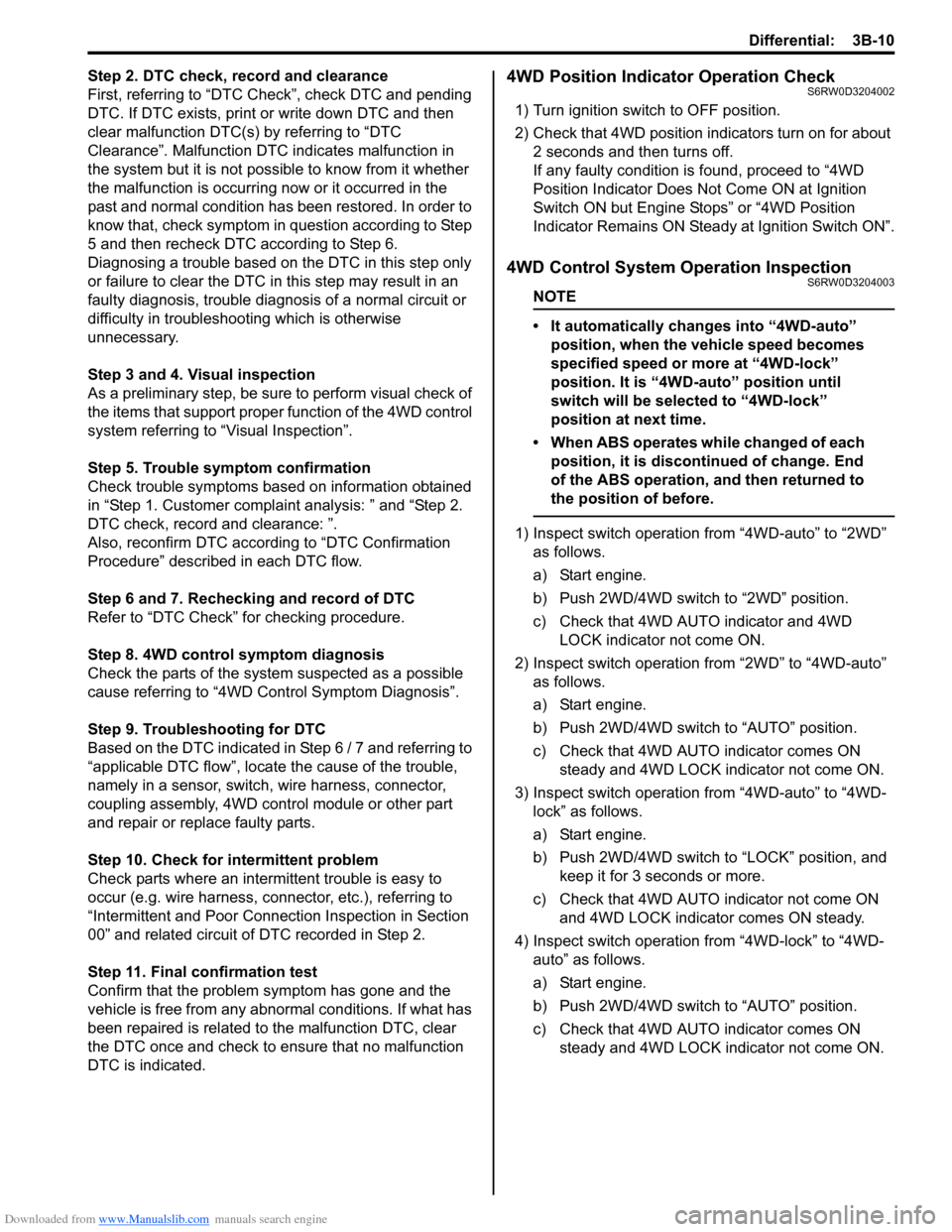
DTC is indicated.4WD Position Indicator Operation CheckS6RW0D3204002
1) Turn ignition switch to OFF position.
2) Check that 4WD position indicators turn on for about
2 seconds and then turns off.
If any faulty condition is found, proceed to “4WD
Position Indicator Does Not Come ON at Ignition
Switch ON but Engine Stops” or “4WD Position
Indicator Remains ON Steady at Ignition Switch ON”.
4WD Control System Operation InspectionS6RW0D3204003
NOTE
• It automatically changes into “4WD-auto”
position, when the vehicle speed becomes
specified speed or more at “4WD-lock”
position. It is “4WD-auto” position until
switch will be selected to “4WD-lock”
position at next time.
• When ABS operates while changed of each
position, it is discontinued of change. End
of the ABS operation, and then returned to
the position of before.
1) Inspect switch operation from “4WD-auto” to “2WD”
as follows.
a) Start engine.
b) Push 2WD/4WD switch to “2WD” position.
c) Check that 4WD AUTO indicator and 4WD
LOCK indicator not come ON.
2) Inspect switch operation from “2WD” to “4WD-auto”
as follows.
a) Start engine.
b) Push 2WD/4WD switch to “AUTO” position.
c) Check that 4WD AUTO indicator comes ON
steady and 4WD LOCK indicator not come ON.
3) Inspect switch operation from “4WD-auto” to “4WD-
lock” as follows.
a) Start engine.
b) Push 2WD/4WD switch to “LOCK” position, and
keep it for 3 seconds or more.
c) Check that 4WD AUTO indicator not come ON
and 4WD LOCK indicator comes ON steady.
4) Inspect switch operation from “4WD-lock” to “4WD-
auto” as follows.
a) Start engine.
b) Push 2WD/4WD switch to “AUTO” position.
c) Check that 4WD AUTO indicator comes ON
steady and 4WD LOCK indicator not come ON.