engine mount SUZUKI SX4 2006 1.G Service Workshop Manual
[x] Cancel search | Manufacturer: SUZUKI, Model Year: 2006, Model line: SX4, Model: SUZUKI SX4 2006 1.GPages: 1556, PDF Size: 37.31 MB
Page 9 of 1556
Downloaded from www.Manualslib.com manuals search engine Precautions: 00-2
Servicing and Handling
WARNING!
Many of service procedures require
disconnection of “A/B” fuse and all air bag
(inflator) module(s) from initiator circuit to
avoid an accidental deployment.
Driver, Passenger, Side and Curtain Air Bag
(Inflator) Modules
• For handling and storage of a live air bag
(inflator) module, select a place where the
ambient temperature below 65 °C (150 °F),
without high humidity and away from
electric noise.
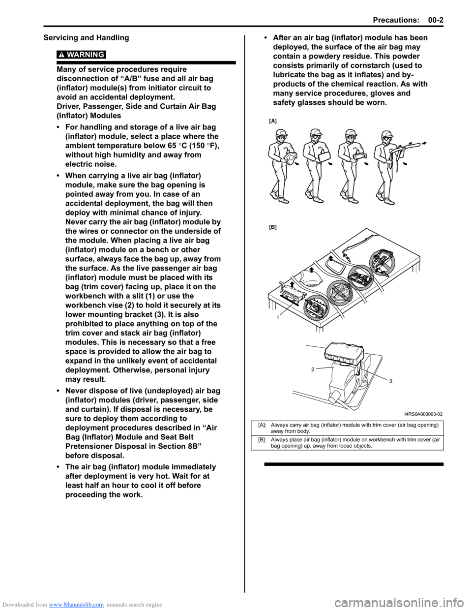
• When carrying a live air bag (inflator)
module, make sure the bag opening is
pointed away from you. In case of an
accidental deployment, the bag will then
deploy with minimal chance of injury.
Never carry the air bag (inflator) module by
the wires or connector on the underside of
the module. When placing a live air bag
(inflator) module on a bench or other
surface, always face the bag up, away from
the surface. As the live passenger air bag
(inflator) module must be placed with its
bag (trim cover) facing up, place it on the
workbench with a slit (1) or use the
workbench vise (2) to hold it securely at its
lower mounting bracket (3). It is also
prohibited to place anything on top of the
trim cover and stack air bag (inflator)
modules. This is necessary so that a free
space is provided to allow the air bag to
expand in the unlikely event of accidental
deployment. Otherwise, personal injury
may result.
• Never dispose of live (undeployed) air bag
(inflator) modules (driver, passenger, side
and curtain). If disposal is necessary, be
sure to deploy them according to
deployment procedures described in “Air
Bag (Inflator) Module and Seat Belt
Pretensioner Disposal in Section 8B”
before disposal.
• The air bag (inflator) module immediately
after deployment is very hot. Wait for at
least half an hour to cool it off before
proceeding the work.• After an air bag (inflator) module has been
deployed, the surface of the air bag may
contain a powdery residue. This powder
consists primarily of cornstarch (used to
lubricate the bag as it inflates) and by-
products of the chemical reaction. As with
many service procedures, gloves and
safety glasses should be worn.
[A]: Always carry air bag (inflator) module with trim cover (air bag opening)
away from body.
[B]: Always place air bag (inflator) module on workbench with trim cover (air
bag opening) up, away from loose objects.
1
2
3
[A]
[B]
I4RS0A000003-02
Page 10 of 1556
Downloaded from www.Manualslib.com manuals search engine 00-3 Precautions:
WARNING!
SDM
• For handling and storage of a SDM, select
a place where the ambient temperature
below 65 °C (150 °F), without high humidity
and away from electric noise.
• During service procedures, be very careful
when handling a Sensing and Diagnostic
Module (SDM). Never strike or jar the SDM.
• Never power up the air bag system when
the SDM is not rigidly attached to the
vehicle. All SDM and mounting bracket
fasteners must be carefully torqued and
the arrow must be pointing toward the
front of the vehicle to ensure proper
operation of the air bag system.
The SDM could be activated when powered
while not rigidly attached to the vehicle
which could cause deployment and result
in personal injury.
WARNING!
Driver and Passenger Seat Belt
Pretensioners
• For handling and storage of a live seat belt
pretensioner, select a place where the
ambient temperature below 65 °C (150 °F),
without high humidity and away from
electric noise.
• Never carry seat belt pretensioner by wire
or connector of pretensioner. When
placing a live seat belt pretensioner on the
workbench or some place like that, never
put something on seat belt pretensioner.
Otherwise, personal injury may result.
• Never dispose of live (inactivated) seat belt
pretensioners (drive and passenger). If
disposal is necessary, be sure to activate
them according to activation procedures
described in “Air Bag (Inflator) Module and
Seat Belt Pretensioner Disposal in Section
8B” before disposal.
• The seat belt pretensioner immediately
after activation is very hot. Wait for at least
half an hour to cool it off before
proceeding the work.
• With many service procedures, gloves and
safety glasses should be worn to prevent
any possible irritation of the skin or eyes.
• Even when the accident was light enough not to
cause air bags to activate, be sure to inspect system
parts and other related parts according to instructions
under “Repair and Inspection Required after Accident
in Section 8B”.
• When servicing parts other than air bag system, if
shocks may be applied to air bag system component
parts, remove those parts beforehand.
• When handling the air bag (inflator) modules (driver,
passenger, side and curtain), seat belt pretensioners
(driver and passenger), forward sensor, side sensors
or SDM, be careful not to drop it or apply an impact to
it. If an excessive impact was applied, never attempt
disassembly or repair but replace it with a new one.
• When grease, cleaning agent, oil, water, etc. has got
onto air bag (inflator) modules (driver, passenger, side
and curtain) or seat belt pretensioners (drive and
passenger), wipe off immediately with a dry cloth.
• Air bag wire harness is included in floor and
instrument panel wire harnesses. Air bag wire
harness branched off from floor and instrument panel
wire harnesses can be identified easily as it is covered
with a yellow protection tube and it has yellow
connectors. Be very careful when handling it.
• When an open in air bag wire harness, damaged wire
harness, connector or terminal is found, replace wire
harness, connectors and terminals as an assembly.
• Do not apply power to the air bag system unless all
components are connected or a diagnostic flow
requests it, as this will set a DTC.
• Never use air bag system component parts from
another vehicle.
• When using electric welding, be sure to disconnect all
air bag (inflator) module connectors and pretensioner
connectors from air bag wire harness respectively.
• Never expose air bag system component parts
directly to hot air (drying or baking the vehicle after
painting) or flames.
• WARNING / CAUTION labels are attached on each
part of air bag system components. Be sure to follow
the instructions.
• After vehicle is completely repaired, perform “Air Bag
Diagnostic System Check in Section 8B”.
General PrecautionsS6RW0D0000002
The WARNING and CAUTION describe some general
precautions that you should observe when servicing a
vehicle. These general precautions apply to many of the
service procedures, and they will not necessarily be
repeated with each procedure to which they apply.
Page 14 of 1556
![SUZUKI SX4 2006 1.G Service Workshop Manual Downloaded from www.Manualslib.com manuals search engine 00-7 Precautions:
Precautions in Servicing 4WD ModelS6RW0D0000014
CAUTION!
• Never perform any of the following [A], [B]
and [C] types of SUZUKI SX4 2006 1.G Service Workshop Manual Downloaded from www.Manualslib.com manuals search engine 00-7 Precautions:
Precautions in Servicing 4WD ModelS6RW0D0000014
CAUTION!
• Never perform any of the following [A], [B]
and [C] types of](/img/20/7612/w960_7612-13.png)
Downloaded from www.Manualslib.com manuals search engine 00-7 Precautions:
Precautions in Servicing 4WD ModelS6RW0D0000014
CAUTION!
• Never perform any of the following [A], [B]
and [C] types of service work.
If it is performed while 4WD-auto mode or
4WD-lock mode is selected, front wheels
(or rear wheels) drive rear wheels (or front
wheels) and vehicle accident, drivetrain
damage and personal injury may result.
Also, if it is performed while 2WD mode is
selected, the coupling may be damaged
because of the difference in revolution
speed between front wheels and rear
wheels.
• When testing with 2-wheel chassis
dynamometer or speedometer tester, be
sure to select 4WD system to 4WD-auto
mode or 4WD-lock mode and use 2-wheel
free roller together or make the vehicle as
front wheel drive by removing propeller
shaft.• When testing with 2-wheel brake tester, be
sure to observe the following instructions.
Otherwise, drivetrain damage and personal
injury may result.
– Shift transaxle to N (Neutral) position.
– Select 4WD system to 2WD mode.
– Run engine at specified idle speed.
– Rotate wheels (tires) by brake tester at
vehicle speed below 5 km/h (3 mile/h).
– Do not rotate wheels (tires) for 1 min. or
more.
• When using On-vehicle type wheel
balancing equipment (1), be sure to select
4WD system to 4WD-auto mode or 4WD-
lock mode and jack up all four wheels, off
the ground completely and support vehicle
with safety stands (2).
Be careful of other wheels, which will
rotate at the same time.
Using it with 2WD mode may damage
coupling.
• This vehicle should be towed under one of
the following conditions:
– With all wheels on a flatbed truck.
– With all wheels on the ground.
Precautions for Catalytic ConverterS6RW0D0000004
For vehicles equipped with a catalytic converter, use
only unleaded gasoline and be careful not to let a large
amount of unburned gasoline enter the converter or it
can be damaged.
• Conduct a spark jump test only when necessary,
make it as short as possible, and do not open the
throttle.
• Conduct engine compression checks within the
shortest possible time.
• Avoid situations which can result in engine misfire
(e.g. starting the engine when the fuel tank is nearly
empty.)[A]: Testing with 2-wheel chassis dynamometer or speedometer tester.
[B]: Driving front wheels, which are jacked up.
[C]: Towing under the condition where either front or rear wheels can not
rotate.
[A]
[B]
[C]
I3RH0A000004-03
I3RH01010062-01
Page 28 of 1556
Downloaded from www.Manualslib.com manuals search engine 0A-5 General Information:
Vehicle Lifting PointsS6RW0D0101005
WARNING!
• Before applying hoist to underbody, always take vehicle balance throughout service into
consideration. Vehicle balance on hoist may change depending on what part to be removed.
• Before lifting up the vehicle, check to be sure that end of hoist arm is not in contact with brake pipe,
fuel pipe, bracket or any other part.
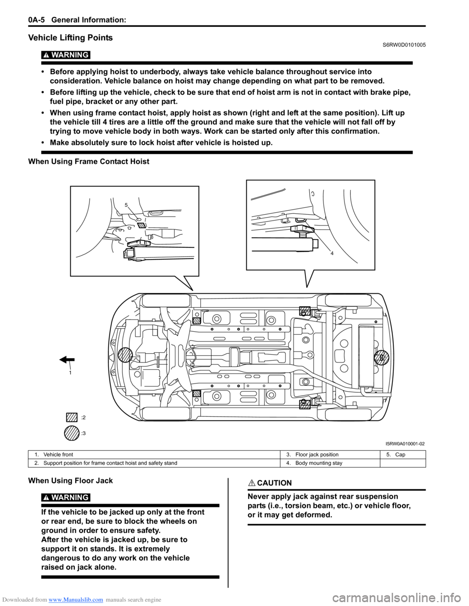
• When using frame contact hoist, apply hoist as shown (right and left at the same position). Lift up
the vehicle till 4 tires are a little off the ground and make sure that the vehicle will not fall off by
trying to move vehicle body in both ways. Work can be started only after this confirmation.
• Make absolutely sure to lock hoist after vehicle is hoisted up.
When Using Frame Contact Hoist
When Using Floor Jack
WARNING!
If the vehicle to be jacked up only at the front
or rear end, be sure to block the wheels on
ground in order to ensure safety.
After the vehicle is jacked up, be sure to
support it on stands. It is extremely
dangerous to do any work on the vehicle
raised on jack alone.
CAUTION!
Never apply jack against rear suspension
parts (i.e., torsion beam, etc.) or vehicle floor,
or it may get deformed.
1
:2
:3
4
c
5
I5RW0A010001-02
1. Vehicle front3. Floor jack position 5. Cap
2. Support position for frame contact hoist and safety stand 4. Body mounting stay
Page 29 of 1556
Downloaded from www.Manualslib.com manuals search engine General Information: 0A-6
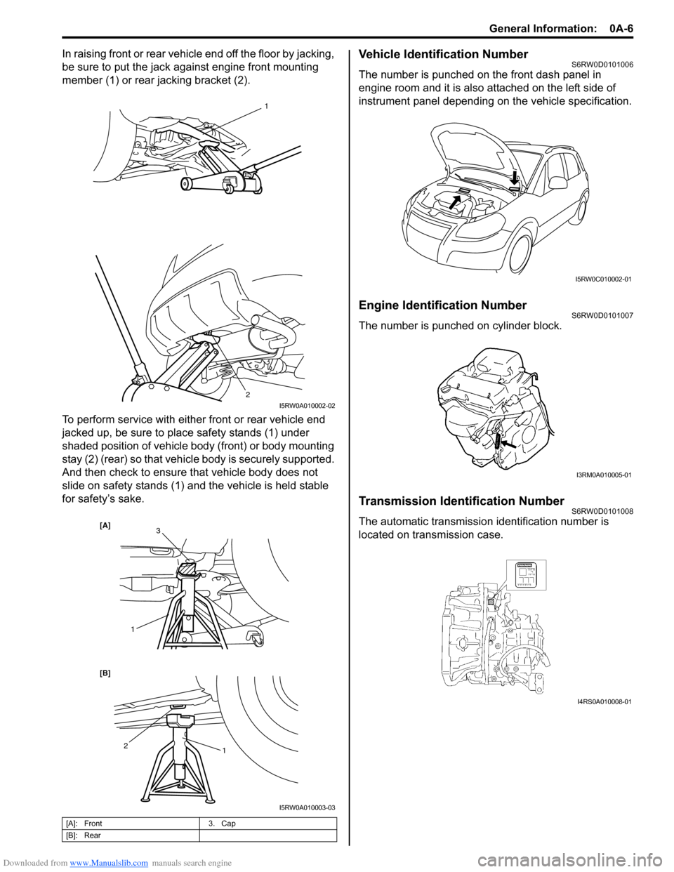
In raising front or rear vehicle end off the floor by jacking,
be sure to put the jack against engine front mounting
member (1) or rear jacking bracket (2).
To perform service with either front or rear vehicle end
jacked up, be sure to place safety stands (1) under
shaded position of vehicle body (front) or body mounting
stay (2) (rear) so that vehicle body is securely supported.
And then check to ensure that vehicle body does not
slide on safety stands (1) and the vehicle is held stable
for safety’s sake.Vehicle Identification NumberS6RW0D0101006
The number is punched on the front dash panel in
engine room and it is also attached on the left side of
instrument panel depending on the vehicle specification.
Engine Identification NumberS6RW0D0101007
The number is punched on cylinder block.
Transmission Identification NumberS6RW0D0101008
The automatic transmission identification number is
located on transmission case.
[A]: Front 3. Cap
[B]: Rear
1
2
I5RW0A010002-02
1 2
[B] [A]
1
3
I5RW0A010003-03
I5RW0C010002-01
I3RM0A010005-01
I4RS0A010008-01
Page 35 of 1556
Downloaded from www.Manualslib.com manuals search engine Maintenance and Lubrication: 0B-4
Engine Oil and Filter ChangeS6RW0D0206004
WARNING!
• New and used engine oil can be
hazardous.
Be sure to read “WARNING” in “General
Precautions in Section 00” and observe
what is written there.
• Step 1) – 7) outlined below must be
performed with ENGINE NOT RUNNING.
For Step 8), be sure to have adequate
ventilation while engine is running.
Before draining engine oil, check engine for oil leakage.
If any evidence of leakage is found, make sure to correct
defective part before proceeding to the following work.
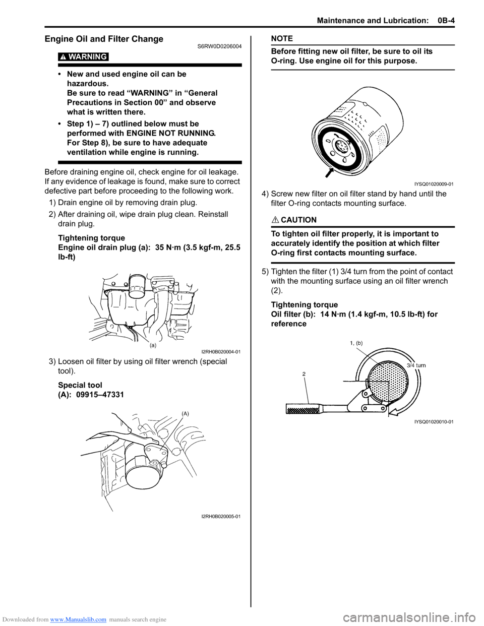
1) Drain engine oil by removing drain plug.
2) After draining oil, wipe drain plug clean. Reinstall
drain plug.
Tightening torque
Engine oil drain plug (a): 35 N·m (3.5 kgf-m, 25.5
lb-ft)
3) Loosen oil filter by using oil filter wrench (special
tool).
Special tool
(A): 09915–47331
NOTE
Before fitting new oil filter, be sure to oil its
O-ring. Use engine oil for this purpose.
4) Screw new filter on oil filter stand by hand until the
filter O-ring contacts mounting surface.
CAUTION!
To tighten oil filter properly, it is important to
accurately identify the position at which filter
O-ring first contacts mounting surface.
5) Tighten the filter (1) 3/4 turn from the point of contact
with the mounting surface using an oil filter wrench
(2).
Tightening torque
Oil filter (b): 14 N·m (1.4 kgf-m, 10.5 lb-ft) for
reference
I2RH0B020004-01
I2RH0B020005-01
IYSQ01020009-01
IYSQ01020010-01
Page 36 of 1556
Downloaded from www.Manualslib.com manuals search engine 0B-5 Maintenance and Lubrication:
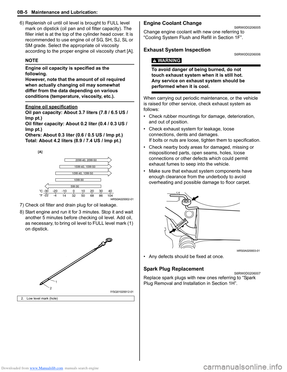
6) Replenish oil until oil level is brought to FULL level
mark on dipstick (oil pan and oil filter capacity). The
filler inlet is at the top of the cylinder head cover. It is
recommended to use engine oil of SG, SH, SJ, SL or
SM grade. Select the appropriate oil viscosity
according to the proper engine oil viscosity chart [A].
NOTE
Engine oil capacity is specified as the
following.
However, note that the amount of oil required
when actually changing oil may somewhat
differ from the data depending on various
conditions (temperature, viscosity, etc.).
Engine oil specification
Oil pan capacity: About 3.7 liters (7.8 / 6.5 US /
lmp pt.)
Oil filter capacity: About 0.2 liter (0.4 / 0.3 US /
lmp pt.)
Others: About 0.3 liter (0.6 / 0.5 US / lmp pt.)
Total: About 4.2 liters (8.9 / 7.4 US / lmp pt.)
7) Check oil filter and drain plug for oil leakage.
8) Start engine and run it for 3 minutes. Stop it and wait
another 5 minutes before checking oil level. Add oil,
as necessary, to bring oil level to FULL level mark (1)
on dipstick.
Engine Coolant ChangeS6RW0D0206005
Change engine coolant with new one referring to
“Cooling System Flush and Refill in Section 1F”.
Exhaust System InspectionS6RW0D0206006
WARNING!
To avoid danger of being burned, do not
touch exhaust system when it is still hot.
Any service on exhaust system should be
performed when it is cool.
When carrying out periodic maintenance, or the vehicle
is raised for other service, check exhaust system as
follows:
• Check rubber mountings for damage, deterioration,
and out of position.
• Check exhaust system for leakage, loose
connections, dents and damages.
If bolts or nuts are loose, tighten them to specification.
• Check nearby body areas for damaged, missing or
mispositioned parts, open seams, holes, loose
connections or other defects which could permit
exhaust fumes to seep into the vehicle.
• Make sure that exhaust system components have
enough clearance from the underbody to avoid
overheating and possible damage to floor carpet.
• Any defects should be fixed at once.
Spark Plug ReplacementS6RW0D0206007
Replace spark plugs with new ones referring to “Spark
Plug Removal and Installation in Section 1H”.
2. Low level mark (hole)
C
Fo o-30
-22-20
-4-10
14 32 50 68 86 104010203040
5W-30
20W-40, 20W-50
10W-30
15W-40, 15W-50
10W-40, 10W-50
[A]
I4RS0A020002-01
IYSQ01020012-01
I4RS0A020003-01
Page 47 of 1556
Downloaded from www.Manualslib.com manuals search engine Table of Contents 1-iii
EGR Valve Removal and Installation (If
Equipped).......................................................... 1B-4
EGR Valve Inspection (If Equipped) ................... 1B-4
PCV Hose Inspection .......................................... 1B-5
PCV Valve Inspection ......................................... 1B-5
Special Tools and Equipment ............................. 1B-5
Special Tool ........................................................ 1B-5
Engine Electrical Devices ....................... 1C-1
Repair Instructions .............................................. 1C-1
Engine Control Module (ECM) Removal and
Installation ......................................................... 1C-1
Manifold Absolute Pressure (MAP) Sensor
Inspection (If Equipped) .................................... 1C-2
Electric Throttle Body Assembly On-Vehicle
Inspection.......................................................... 1C-2
Electric Throttle Body System Calibration ........... 1C-5
Accelerator Pedal Position (APP) Sensor
Assembly On-Vehicle Inspection ...................... 1C-5
Accelerator Pedal Position (APP) Sensor
Assembly Removal and Installation .................. 1C-5
Accelerator Pedal Position (APP) Sensor
Assembly Inspection ......................................... 1C-6
Engine Coolant Temperature (ECT) Sensor
Removal and Installation................................... 1C-7
Engine Coolant Temperature (ECT) Sensor
Inspection.......................................................... 1C-7
Heated Oxygen Sensor (HO2S-1 and HO2S-
2) Heater On-Vehicle Inspection (If
Equipped).......................................................... 1C-8
Heated Oxygen Sensor (HO2S-1 and HO2S-
2) Removal and Installation (If Equipped) ......... 1C-8
Camshaft Position (CMP) Sensor Removal
and Installation .................................................. 1C-9
Camshaft Position (CMP) Sensor Inspection ...... 1C-9
Crankshaft Position (CKP) Sensor Removal
and Installation ................................................ 1C-10
Crankshaft Position (CKP) Sensor Inspection .. 1C-11
Knock Sensor Removal and Installation ........... 1C-11
Main Relay, Fuel Pump Relay, Starting Motor
Control Relay, Throttle Actuator Control
Relay and Radiator Cooling Fan Relay
Inspection........................................................ 1C-12
Mass Air Flow (MAF) and Intake Air
Temperature (IAT) Sensor On-Vehicle
Inspection........................................................ 1C-12
Mass Air Flow (MAF) and Intake Air
Temperature (IAT) Sensor Removal and
Installation ....................................................... 1C-13
Intake Air Temperature (IAT) Sensor
Inspection........................................................ 1C-13
Specifications..................................................... 1C-14
Tightening Torque Specifications ...................... 1C-14
Engine Mechanical .................................. 1D-1
General Description ............................................. 1D-1
Engine Construction Description ......................... 1D-1
Camshaft Position Control (VVT Variable
Valve Timing) System Description .................... 1D-3Diagnostic Information and Procedures ............1D-5
Compression Check ............................................1D-5
Engine Vacuum Check........................................1D-6
Valve Lash (Clearance) Inspection .....................1D-7
Repair Instructions ............................................1D-10
Air Intake System Components.........................1D-10
Air Cleaner Filter Removal and Installation .......1D-10
Air Cleaner Filter Inspection and Cleaning........1D-10
Air Cleaner Assembly Removal and
Installation .......................................................1D-11
Cylinder Head Cover Removal and
Installation .......................................................1D-11
Throttle Body and Intake Manifold
Components ....................................................1D-13
Throttle Body On-Vehicle Inspection.................1D-14
Electric Throttle Body Assembly Removal and
Installation .......................................................1D-14
Throttle Body Cleaning......................................1D-14
Intake Manifold Removal and Installation .........1D-15
Engine Mountings Components ........................1D-16
Engine Assembly Removal and Installation ......1D-17
Timing Chain Cover Components .....................1D-22
Timing Chain Cover Removal and Installation ..1D-23
Timing Chain Cover Inspection .........................1D-25
Oil Control Valve Removal and Installation
(For Engine with VVT) .....................................1D-26
Oil Control Valve Inspection (For Engine with
VVT) ................................................................1D-26
Timing Chain and Chain Tensioner
Components ....................................................1D-27
Timing Chain and Chain Tensioner Removal
and Installation ................................................1D-27
Timing Chain and Chain Tensioner Inspection ..1D-31
Camshaft, Tappet and Shim Components ........1D-32
Camshaft, Tappet and Shim Removal and
Installation .......................................................1D-33
Camshaft, Tappet and Shim Inspection ............1D-36
Valves and Cylinder Head Components ...........1D-39
Valves and Cylinder Head Removal and
Installation .......................................................1D-40
Valves and Cylinder Head Disassembly and
Assembly.........................................................1D-42
Valves and Valve Guides Inspection.................1D-45
Cylinder Head Inspection ..................................1D-47
Valve Spring Inspection ....................................1D-48
Pistons, Piston Rings, Connecting Rods and
Cylinders Components ....................................1D-49
Pistons, Piston Rings, Connecting Rods and
Cylinders Removal and Installation .................1D-49
Pistons, Piston Rings, Connecting Rods and
Cylinders Disassembly and Assembly ............1D-51
Cylinders, Pistons and Piston Rings
Inspection ........................................................1D-52
Piston Pins and Connecting Rods Inspection ...1D-54
Crank Pin and Connecting Rod Bearings
Inspection ........................................................1D-55
Main Bearings, Crankshaft and Cylinder
Block Components ..........................................1D-59
Main Bearings, Crankshaft and Cylinder
Block Removal and Installation .......................1D-60
Page 49 of 1556
Downloaded from www.Manualslib.com manuals search engine Table of Contents 1-v
Diagnostic Information and Procedures ............ 1H-4
Ignition System Symptom Diagnosis................... 1H-4
Reference Waveform of Ignition System............. 1H-4
Ignition System Check ........................................ 1H-4
Ignition Spark Test .............................................. 1H-6
Repair Instructions .............................................. 1H-6
High-Tension Cord Removal and Installation...... 1H-6
High-Tension Cord Inspection ............................ 1H-7
Spark Plug Removal and Installation .................. 1H-7
Spark Plug Inspection ......................................... 1H-7
Ignition Coil Assembly (Including Ignitor)
Removal and Installation................................... 1H-8
Ignition Coil Assembly (Including Ignitor)
Inspection.......................................................... 1H-8
Ignition Timing Inspection ................................... 1H-8
Specifications..................................................... 1H-10
Tightening Torque Specifications ...................... 1H-10
Special Tools and Equipment ........................... 1H-10
Special Tool ...................................................... 1H-10
Starting System ......................................... 1I-1
Schematic and Routing Diagram ......................... 1I-1
Cranking System Circuit Diagram ........................ 1I-1
Diagnostic Information and Procedures ............. 1I-1
Cranking System Symptom Diagnosis ................. 1I-1
Cranking System Test.......................................... 1I-3
Repair Instructions ............................................... 1I-4
Starting Motor Dismounting and Remounting ...... 1I-4
Starting Motor Components ................................. 1I-5
Starting Motor Inspection ..................................... 1I-6
Specifications........................................................ 1I-9
Cranking System Specifications........................... 1I-9
Tightening Torque Specifications ......................... 1I-9
Special Tools and Equipment.............................. 1I-9
Recommended Service Material .......................... 1I-9
Charging System ...................................... 1J-1
General Description ............................................. 1J-1
Battery Description .............................................. 1J-1
Generator Description ......................................... 1J-3
Diagnostic Information and Procedures ............ 1J-4
Battery Inspection ............................................... 1J-4
Generator Symptom Diagnosis ........................... 1J-4
Generator Test (Undercharged Battery
Check) ............................................................... 1J-5
Generator Test (Overcharged Battery Check) .... 1J-6
Repair Instructions .............................................. 1J-6
Jump Starting in Case of Emergency.................. 1J-6
Battery Dismounting and Remounting ................ 1J-7
Water Pump / Generator Drive Belt Tension
Inspection and Adjustment ................................ 1J-7
Water Pump / Generator Drive Belt Removal
and Installation .................................................. 1J-8
Generator Dismounting and Remounting............ 1J-9
Generator Components..................................... 1J-10
Generator Inspection......................................... 1J-11
Specifications ..................................................... 1J-13
Charging System Specifications ....................... 1J-13
Tightening Torque Specifications ...................... 1J-13
Exhaust System ....................................... 1K-1
General Description .............................................1K-1
Exhaust System Description ............................... 1K-1
Diagnostic Information and Procedures ............1K-1
Exhaust System Check ....................................... 1K-1
Repair Instructions ..............................................1K-2
Exhaust System Components ............................. 1K-2
Exhaust Manifold Removal and Installation ........ 1K-3
Exhaust Pipe and Muffler Removal and
Installation ......................................................... 1K-4
Specifications .......................................................1K-5
Tightening Torque Specifications ........................ 1K-5
Page 61 of 1556
Downloaded from www.Manualslib.com manuals search engine Engine General Information and Diagnosis: 1A-11
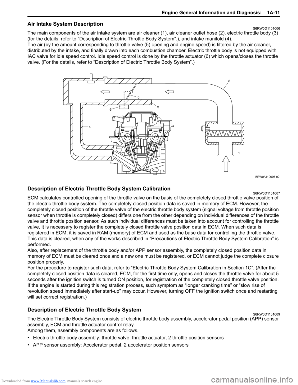
Air Intake System DescriptionS6RW0D1101006
The main components of the air intake system are air cleaner (1), air cleaner outlet hose (2), electric throttle body (3)
(for the details, refer to “Description of Electric Throttle Body System”.), and intake manifold (4).
The air (by the amount corresponding to throttle valve (5) opening and engine speed) is filtered by the air cleaner,
distributed by the intake, and finally drawn into each combustion chamber. Electric throttle body is not equipped with
IAC valve for idle speed control. Idle speed control is done by the throttle actuator (6) which opens/closes the throttle
valve. (For the details, refer to “Description of Electric Throttle Body System”.)
Description of Electric Throttle Body System CalibrationS6RW0D1101007
ECM calculates controlled opening of the throttle valve on the basis of the completely closed throttle valve position of
the electric throttle body system. The completely closed position data is saved in memory of ECM. However, the
completely closed position of the throttle valve of the electric throttle body system (signal voltage from throttle position
sensor when throttle is completely closed) differs one from the other depending on individual differences of the throttle
valve and throttle position sensor. As such individual differences must be taken into account for controlling the throttle
valve, it is necessary to register the completely closed throttle valve position data in ECM. When such data is
registered in ECM, it is saved in RAM (memory) of ECM and used as the base data for controlling the throttle valve.
This data is cleared, when any of the works described in “Precautions of Electric Throttle Body System Calibration” is
performed.
Also, after replacement of the throttle body and/or APP sensor assembly, the completely closed position data in
memory of ECM must be cleared once and a new one must be registered, or ECM cannot judge the complete closure
position properly.
For the procedure to register such data, refer to “Electric Throttle Body System Calibration in Section 1C”. (After the
completely closed position data is cleared, ECM, for the first time only, opens and closes the throttle valve for about 5
seconds after the ignition switch is turned ON position, for registration of the completely closed throttle valve position.
If the engine is started during this registration process, such symptom as “longer cranking time” or “slow rise of
revolution speed immediately after start-up” may occur. However, turning OFF the ignition switch once and restarting
will set correct registration.)
Description of Electric Throttle Body SystemS6RW0D1101009
The Electric Throttle Body System consists of electric throttle body assembly, accelerator pedal position (APP) sensor
assembly, ECM and throttle actuator control relay.
Among them, assembly components are as follows.
• Electric throttle body assembly: throttle valve, throttle actuator, 2 throttle position sensors
• APP sensor assembly: Accelerator pedal, 2 accelerator position sensors
42
1
3
5
6
I5RW0A110006-02