engine TATA SAFARI 2015 Service Manual
[x] Cancel search | Manufacturer: TATA, Model Year: 2015, Model line: SAFARI, Model: TATA SAFARI 2015Pages: 161, PDF Size: 2.55 MB
Page 108 of 161
108
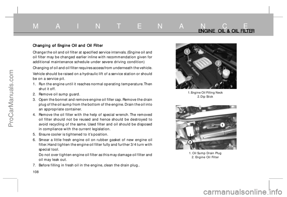
Changing of Engine Oil and Oil Filter Changing of Engine Oil and Oil FilterChanging of Engine Oil and Oil Filter Changing of Engine Oil and Oil Filter
Changing of Engine Oil and Oil Filter
Change the oil and oil filter at specified service intervals. (Engine oil and
oil filter may be changed earlier inline with recommendation given for
additional maintenance schedule under severe driving condition)
Changing of oil and oil filter requires access from underneath the vehicle.
Vehicle should be raised on a hydraulic lift of a service station or should
be on a service pit.
1 . Run the engine until it reaches normal operating temperature. Then
shut it off.
2. Remove oil sump guard.
3. Open the bonnet and remove engine oil filler cap. Remove the drain
plug of the oil sump from the bottom of the engine. Drain the oil into
an appropriate container.
4. Remove the oil filter with the help of special wrench. The removed
oil filter should not be reused and hence should be destroyed to
avoid recycling of the same. Used filter and oil should be disposed
in compliance with the current legislation.
5. Ensure cooler is tightened to it’s position.
6. Smear a little fresh engine oil on rubber gasket of new engine oil
filter. Hand tighten the engine oil filter fully and further 3/4 turn with
special tool.
Do not over tighten engine oil filter as this may damage oil filter and
oil may leak out.
7. Before filling in fresh oil in the engine, clean the drain plug..
ENGINE OIL & OIL FIL ENGINE OIL & OIL FILENGINE OIL & OIL FIL ENGINE OIL & OIL FIL
ENGINE OIL & OIL FIL
TER TERTER TER
TER
1. Engine Oil Filling Neck
2. Dip Stick
1. Oil Sump Drain Plug
2. Engine Oil Filter
M A I N T E N A N C E
2 22 2
21 11 1
1
ProCarManuals.com
Page 109 of 161
109
FUEL FIL FUEL FILFUEL FIL FUEL FIL
FUEL FIL
TER & FUEL SY TER & FUEL SYTER & FUEL SY TER & FUEL SY
TER & FUEL SY
STEM STEMSTEM STEM
STEM
6. Refit the drain plug using a new sealing washer. Tighten
drain plug to 5 mkg. torque.
7. Fill, recommended quantity of fresh engine oil in the crank
case and secure the oil filler cap in its place.
8. Start the engine and run for a few minutes. The engine oil
pressure indicator lamp should go ‘off ’ after starting the
engine.
9. Check for engine oil leakages.
10. Stop the engine and recheck engine oil level after a few
minutes. If necessary add oil to bring the level to the upper
mark on the dipstick.
NOTICE NOTICENOTICE NOTICE
NOTICE
Use of reclaimed oil is not recommended
Priming Pump Priming PumpPriming Pump Priming Pump
Priming Pump
Priming pump is used for priming the fuel manually after
overhauling of the engine or after refitment of fuel lines. Pump
the fuel by means of priming pump until all air in the fuel line is
removed. Before cranking the engine ensure that there is no air
in the fuel system.
NOTICE NOTICENOTICE NOTICE
NOTICE
Please do not loosen/remove high pressure pipes and injectors
for air bleeding in the fuel.
M A I N T E N A N C E
F FF F
F
uel & F uel & Fuel & F uel & F
uel & F
ilt iltilt ilt
ilt
er D er Der D er D
er D
r rr r
r
aining ainingaining aining
aining
Loosen drain plugs by 1-2 turn and drain out water and other
sediments from fuel filter bowls depending on operating
conditions to ensure that no water is allowed to enter the fuel
system.
S SS S
S
edimen edimenedimen edimen
edimen
t tt t
t
er er er er
er
W WW W
W
a aa a
a
t tt t
t
er D er Der D er D
er D
r rr r
r
aining ainingaining aining
aining
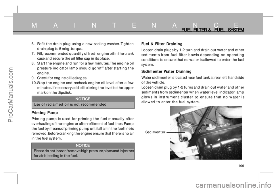
Water sedimenter is located near fuel tank at rear left hand side
of the vehicle.
Loosen drain plug by 1-2 turns and drain out water and other
sediments from sedimenter when water level indicator lamp
glows in instrument cluster to ensure that no water is
allowed to enter the fuel system.
Sedimenter
ProCarManuals.com
Page 110 of 161
110
Gear Box Oil Gear Box OilGear Box Oil Gear Box Oil
Gear Box Oil
C CC C
C
heck heckheck heck
heck
ing of Oil L ing of Oil Ling of Oil L ing of Oil L
ing of Oil L
e ee e
e
v vv v
v
el elel el
el
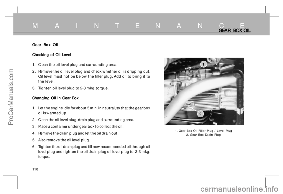
1. Clean the oil level plug and surrounding area.
2 . Remove the oil level plug and check whether oil is dripping out.
Oil level must not be below the filler plug. Add oil to bring it to
the level.
3. Tighten oil level plug to 2-3 mkg. torque.
C CC C
C
hanging Oil in G hanging Oil in Ghanging Oil in G hanging Oil in G
hanging Oil in G
ear B ear Bear B ear B
ear B
o oo o
o
x xx x
x
1. Let the engine idle for about 5 min. in neutral, so that the gear box
oil is warmed up.
2. Clean the oil level plug, drain plug and surrounding area.
3. Place a container under gear box to collect the oil.
4. Remove the drain plug and let the oil drain out.
5. Also remove the oil level plug.
6. Tighten the oil drain plug and fill new recommended oil through oil
level plug and tighten the oil drain plug oil level plug to 2-3 mkg.
torque.
GEAR BO GEAR BOGEAR BO GEAR BO
GEAR BO
X OIL X OILX OIL X OIL
X OIL
1. Gear Box Oil Filler Plug / Level Plug
2. Gear Box Drain Plug
1
2
M A I N T E N A N C E
ProCarManuals.com
Page 115 of 161
115
CL CLCL CL
CL
UT UTUT UT
UT
CH, CH,CH, CH,
CH,
BR BR BR BR
BR
AKE AKEAKE AKE
AKE
,, ,,
,
PO PO PO PO
PO
WER STEERING WER STEERINGWER STEERING WER STEERING
WER STEERING
Clutch Fluid Clutch FluidClutch Fluid Clutch Fluid
Clutch Fluid
The Tata Safari vehicle is equipped with a diaphragm type clutch Which is
hydraulically actuated.
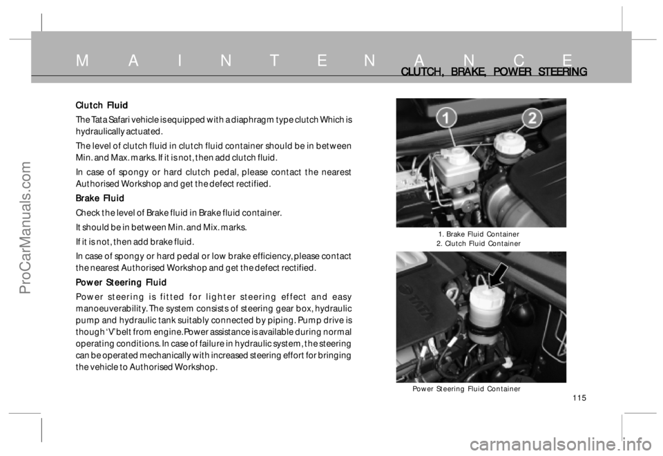
The level of clutch fluid in clutch fluid container should be in between
Min. and Max. marks. If it is not, then add clutch fluid.
In case of spongy or hard clutch pedal, please contact the nearest
Authorised Workshop and get the defect rectified.
Brake Fluid Brake FluidBrake Fluid Brake Fluid
Brake Fluid
Check the level of Brake fluid in Brake fluid container.
It should be in between Min. and Mix. marks.
If it is not, then add brake fluid.
In case of spongy or hard pedal or low brake efficiency, please contact
the nearest Authorised Workshop and get the defect rectified.
Power Steering Fluid Power Steering FluidPower Steering Fluid Power Steering Fluid
Power Steering Fluid
Power steering is fitted for lighter steering effect and easy
manoeuverability. The system consists of steering gear box, hydraulic
pump and hydraulic tank suitably connected by piping. Pump drive is
though ‘V’ belt from engine. Power assistance is available during normal
operating conditions. In case of failure in hydraulic system, the steering
can be operated mechanically with increased steering effort for bringing
the vehicle to Authorised Workshop.
M A I N T E N A N C E
1. Brake Fluid Container
2. Clutch Fluid Container
Power Steering Fluid Container
ProCarManuals.com
Page 116 of 161
116
POWER STEERING POWER STEERINGPOWER STEERING POWER STEERING
POWER STEERING
Procedure for Oil Filling and Bleeding of Power Procedure for Oil Filling and Bleeding of PowerProcedure for Oil Filling and Bleeding of Power Procedure for Oil Filling and Bleeding of Power
Procedure for Oil Filling and Bleeding of Power
Steering SteeringSteering Steering
Steering (Ensure that Power Steering fluid reservoir is totally
clean before starting the work)
1 . Fill the reservoir nearly full. Crank the engine for 10
seconds without allowing it to start (if possible). If engine
does start, shut the engine immediately. Check & refill
the reservoir repeat atleast three times, each time
checking & refilling the reservoir.
2 . Check for leakage in the system and if noticed take
corrective action.
3 . Start the engine and steer the vehicle from full left to full
right turns 3-4 times.
4 . Add fluid if necessary to maintain the level upto filter top.
NOTICE NOTICENOTICE NOTICE
NOTICE
Do not force the wheel against lock position either
extreme left or right. The power steering pump may get
damaged. Hold it lightly.
5 . When the engine is at steady speed, check for bubble
or foaming in the oil. If present it indicates that air is
getting sucked into the systems. Check the suction
line/fittings and correct if necessary.
6 . Once the system is bled properly and free from foaming
there should not be any appreciable change in oil level
in the reservoir, when the engine is started or stopped
repeatedly.
7 . Now the system is ready for driving.
Final oil level should be at ‘H’ mark on dip stick.
NOTICE NOTICENOTICE NOTICE
NOTICE
* Do not allow fluid level to drop significantly or run out
of the reservoir during the above operation. This may
induce air to the system.
* Do not start the engine without oil in the power steering
system. This will result in serious damage to the
pump. In case of emergency disconnect the pump belt
and then start the engine.
* Always use recommended oil from closed containers.
Any dirty oil poured in the system will result in damage
to pump and gear box.
M A I N T E N A N C E
ProCarManuals.com
Page 117 of 161
117
L LL L
L
oad C oad Coad C oad C
oad C
onscious P onscious Ponscious P onscious P
onscious P
r rr r
r
essur essuressur essur
essur
e R e Re R e R
e R
educing educing educing educing
educing
V VV V
V
alv alvalv alv
alv
e (I e (Ie (I e (I
e (I
f fitt f fittf fitt f fitt
f fitt
ed) ed)ed) ed)
ed)
( Not applicable in ABS system) ( Not applicable in ABS system)( Not applicable in ABS system) ( Not applicable in ABS system)
( Not applicable in ABS system)
A load conscious pressure reducing valve eliminates the
possibility of rear wheels from locking and achieves optimum
braking in any load condition of the vehicle.
The valve, is fitted on RH long member connecting it to rear
axle through its link and control spring.
If any, alteration is done in rear suspension, the performance
of this valve will be impaired.
R RR R
R
emot emotemot emot
emot
e B e Be B e B
e B
y-pass y-pass y-pass y-pass
y-pass
V VV V
V
alv alvalv alv
alv
e (I e (Ie (I e (I
e (I
f fitt f fittf fitt f fitt
f fitt
ed) ed)ed) ed)
ed)
(Applicable in ABS system) (Applicable in ABS system)(Applicable in ABS system) (Applicable in ABS system)
(Applicable in ABS system)
The by-pass valve is provided in the rear brake circuit between
tandem master cylinder and ABS unit. The by-pass valve
bypasses the ABS unit in rear only braking (i.e. front brake
failed) condition. The feedback of front line pressure is
provided to the by-pass valve. in case of front brake failure,
the low front line presure being sensed by the by-pass valve
and the 100% brake line pressure from tandem master
cylinder is applied on to the rear brakes without reduction
in pressure.
M A I N T E N A N C EL LL L
L
CR CRCR CR
CR
V (IF FIT V (IF FITV (IF FIT V (IF FIT
V (IF FIT
TED), TED),TED), TED),
TED),
REMO REMO REMO REMO
REMO
TE BY P TE BY PTE BY P TE BY P
TE BY P
ASS ASS ASS ASS
ASS
V VV V
V
AL ALAL AL
AL
VE AND ECU VE AND ECUVE AND ECU VE AND ECU
VE AND ECU
ECU : ECU :ECU : ECU :
ECU :
DICOR engine common rail system consists of ECU, sensors
and actuators. The Electronic control unit (ECU) is a 32 bit
microprocessor which controls the injection parameters as well
as some of the vehicle related outputs. The ECU receives input
from various sensors located on the engine and the vehicle to
decide the injected quantity and injection timing best suited
for the engine to work with maximum efficiency and safety.
ECU is fitted inside the engine compartment.
C CC C
C
AUTIONS AUTIONSAUTIONS AUTIONS
AUTIONS
• •• •
•DO NOT DO NOT DO NOT DO NOT
DO NOT wash engine compartment with high
pressure water
• •• •
•DO NOT DO NOTDO NOT DO NOT
DO NOT tamper with ECU sensors and connectors
• •• •
•DO NOT DO NOTDO NOT DO NOT
DO NOT remove battery connections when the ignition
switch is in ‘ON’ position ( This may damage ECU)
• •• •
•AV AVAV AV
AV
OID OIDOID OID
OID jump start/push start, Use fully charged battery.
• •• •
•DO NO DO NODO NO DO NO
DO NO
T T T T
T run the vehicle if ‘CHECK ENGINE’ lamp on
dashboard is ‘ON.
• •• •
•If any abnormality in performance of engine occurs - like
lack of power- the vehicle to be taken to the
T TT T
T
A AA A
A
T TT T
T
A MO A MOA MO A MO
A MO
T TT T
T
ORS ORSORS ORS
ORS
authorised service outlet.
ProCarManuals.com
Page 118 of 161
118
B BB B
B
A AA A
A
T TT T
T
TER TERTER TER
TER
Y YY Y
Y
Battery BatteryBattery Battery
Battery
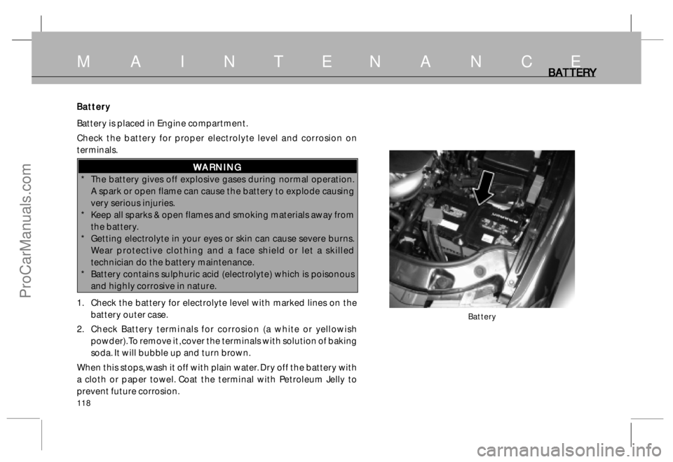
Battery is placed in Engine compartment.
Check the battery for proper electrolyte level and corrosion on
terminals.
W WW W
W
ARNING ARNINGARNING ARNING
ARNING
* The battery gives off explosive gases during normal operation.
A spark or open flame can cause the battery to explode causing
very serious injuries.
* Keep all sparks & open flames and smoking materials away from
the battery.
* Getting electrolyte in your eyes or skin can cause severe burns.
Wear protective clothing and a face shield or let a skilled
technician do the battery maintenance.
* Battery contains sulphuric acid (electrolyte) which is poisonous
and highly corrosive in nature.
1. Check the battery for electrolyte level with marked lines on the
battery outer case.
2. Check Battery terminals for corrosion (a white or yellowish
powder). To remove it, cover the terminals with solution of baking
soda. It will bubble up and turn brown.
When this stops, wash it off with plain water. Dry off the battery with
a cloth or paper towel. Coat the terminal with Petroleum Jelly to
prevent future corrosion.
Battery
M A I N T E N A N C E
ProCarManuals.com
Page 119 of 161
119
B BB B
B
A AA A
A
T TT T
T
TER TERTER TER
TER
Y YY Y
Y
,, ,,
,
ST ST ST ST
ST
AR ARAR AR
AR
TING TING TING TING
TING
THE ENGINE THE ENGINE THE ENGINE THE ENGINE
THE ENGINE
WITH JUMP LEADS WITH JUMP LEADSWITH JUMP LEADS WITH JUMP LEADS
WITH JUMP LEADS
The use of a wrench to loosen and remove cables from the
terminals should be made. Always disconnect the negative
(-ve) cable first and reconnect it last. Clean the battery
terminals with a terminal cleaning tool or wire brush.
Reconnect and tighten the cables, coat the terminals with
petroleum jelly. If you need to connect the battery to a
charger, disconnect both cables to prevent damage to the
vehicle’s electrical system.
NOTICE NOTICENOTICE NOTICE
NOTICE
Charging the battery with the cables connected can
seriously damage your vehicle’s electronic controls.
Detach the battery cables before connecting battery to
a charger.
* Swallowing electrolyte can cause fatal poisoning if
immediate action is not taken.
Starting the Engine with Jump Leads Starting the Engine with Jump LeadsStarting the Engine with Jump Leads Starting the Engine with Jump Leads
Starting the Engine with Jump Leads
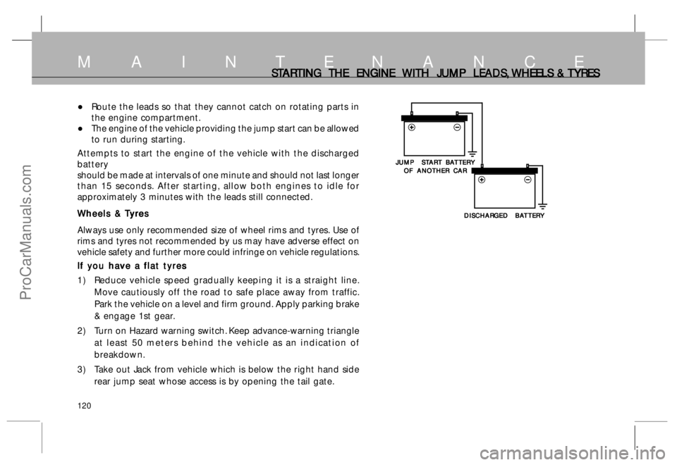
Your Safari with a discharged battery may be started by
transferring electrical power from a battery in another vehicle.
This may be dangerous as any deviation from the following
instructions could lead to personal injury or damage
resulting from battery explosion, as well as the damage to
the electrical systems in both vehicles.• Never expose the battery to open flames or sparks.
• Do not allow battery electrolyte to come in contact with
eyes, skins, fabrics or painted surfaces. The fluid
contains sulphuric acid which can cause injuries and
damage in the event of direct contact.
• To lessen the risk of injury wear eye protection when
working near any battery.
• Make sure that battery providing the jump start has the
same voltage as the battery in your vehicle (12 V). Its
capacity must not be substantially lower than that of the
discharged battery. The voltage and capacity are given
on the batteries.
• Do not disconnect the discharged battery from the vehicle.
• Switch off all unnecessary electrical loads.
• Do not lean over the battery during jump starting.
• Do not allow the terminals of one lead to touch those of
the other lead.
• Apply hand brake. Place gear shift lever to neutral.
Connect Leads in the Order as shown Connect Leads in the Order as shownConnect Leads in the Order as shown Connect Leads in the Order as shown
Connect Leads in the Order as shown
on next page on next page on next page on next page
on next page
•Do not connect lead to negative terminal of discharged
battery.
•The connection point should be as far away from the
discharged battery as possible.
M A I N T E N A N C E
ProCarManuals.com
Page 120 of 161
120
ST STST ST
ST
AR ARAR AR
AR
TING TING TING TING
TING
THE ENGINE THE ENGINE THE ENGINE THE ENGINE
THE ENGINE
WITH JUMP LEADS, WITH JUMP LEADS,WITH JUMP LEADS, WITH JUMP LEADS,
WITH JUMP LEADS,
WHEELS & WHEELS & WHEELS & WHEELS &
WHEELS &
T TT T
T
YRES YRESYRES YRES
YRES
•Route the leads so that they cannot catch on rotating parts in
the engine compartment.
•The engine of the vehicle providing the jump start can be allowed
to run during starting.
Attempts to start the engine of the vehicle with the discharged
battery
should be made at intervals of one minute and should not last longer
than 15 seconds. After starting, allow both engines to idle for
approximately 3 minutes with the leads still connected.
W WW W
W
heels & heels & heels & heels &
heels &
T TT T
T
yr yryr yr
yr
es eses es
es
Always use only recommended size of wheel rims and tyres. Use of
rims and tyres not recommended by us may have adverse effect on
vehicle safety and further more could infringe on vehicle regulations.
If you have a flat tyres If you have a flat tyresIf you have a flat tyres If you have a flat tyres
If you have a flat tyres
1) Reduce vehicle speed gradually keeping it is a straight line.
Move cautiously off the road to safe place away from traffic.
Park the vehicle on a level and firm ground. Apply parking brake
& engage 1st gear.
2) Turn on Hazard warning switch. Keep advance-warning triangle
at least 50 meters behind the vehicle as an indication of
breakdown.
3) Take out Jack from vehicle which is below the right hand side
rear jump seat whose access is by opening the tail gate.
M A I N T E N A N C E
JUMP ST JUMP STJUMP ST JUMP ST
JUMP ST
AR ARAR AR
AR
T B T BT B T B
T B
A AA A
A
T TT T
T
TER TERTER TER
TER
Y YY Y
Y
OF ANOTHER CAR OF ANOTHER CAROF ANOTHER CAR OF ANOTHER CAR
OF ANOTHER CAR
DISCHAR DISCHARDISCHAR DISCHAR
DISCHAR
GED B GED BGED B GED B
GED B
A AA A
A
T TT T
T
TER TERTER TER
TER
Y YY Y
Y
ProCarManuals.com
Page 127 of 161
127
Maintaining the car when not in extended use : Maintaining the car when not in extended use :Maintaining the car when not in extended use : Maintaining the car when not in extended use :
Maintaining the car when not in extended use :
Park the car in covered, dry and if possible well-ventilated
premises.
Engage a gear.
Remove the cables from the battery terminals (first remove
the cable from the negative terminal).
Make sure the handbrake is not engaged.
Clean and protect the painted parts using protective wax.
Clean and protect the shiny metal parts using commercially
available special compounds.
Sprinkle talcum powder on the rubber windscreen wiper and
rear window wiper blades and lift them off the glass.
Slightly open the windows.
Cover the car with a cloth or perforated plastic sheet. Do
not use sheets of imperforated plastic as they do not allow
moisture on the car body to evaporate.
Inflate the tyres to 0.5 bar above the normal specified
pressure and check it at regular intervals.
Check the battery charge every six weeks.
Do not drain the engine cooling system.
VEHICLE C VEHICLE CVEHICLE C VEHICLE C
VEHICLE C
ARE AREARE ARE
ARE
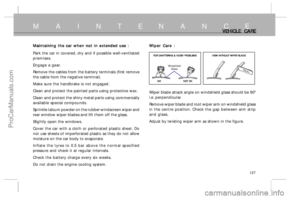
Wiper Care : Wiper Care :Wiper Care : Wiper Care :
Wiper Care :
Wiper blade attack angle on windshield glass should be 90
0
i.e. perpendicular.
Remove wiper blade and root wiper arm on windshield glass
in the centre position. Check the gap between arm strip
and glass.
Adjust by twisting wiper arm as shown in the figure.
OK OKOK OK
OK FOR CHA FOR CHAFOR CHA FOR CHA
FOR CHA
T TT T
T
TERING & NOISY PR TERING & NOISY PRTERING & NOISY PR TERING & NOISY PR
TERING & NOISY PR
OBLEMS OBLEMSOBLEMS OBLEMS
OBLEMS
NO NONO NO
NO
T OK T OKT OK T OK
T OK Windshield
GlassVIE VIEVIE VIE
VIE
W W W W
W
WITHOUT WITHOUT WITHOUT WITHOUT
WITHOUT
WIPER BL WIPER BLWIPER BL WIPER BL
WIPER BL
ADE ADEADE ADE
ADE
M A I N T E N A N C E
ProCarManuals.com