TOYOTA AVENSIS 2005 Service Repair Manual
AVENSIS 2005
TOYOTA
TOYOTA
https://www.carmanualsonline.info/img/14/57441/w960_57441-0.png
TOYOTA AVENSIS 2005 Service Repair Manual
Trending: oil capacity, Oil, MOTOR, airbag off, steering wheel, height, recommended oil
Page 1021 of 5135
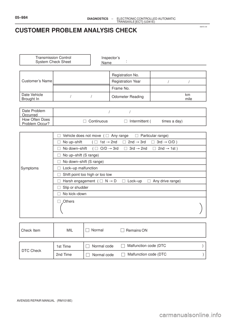
0567O±09
Transmission Control
System Check SheetInspector 's
Name:
Customer 's Name
Registration No.
Registration Year
Frame No.
Date Vehicle
Brought InOdometer Readingkm
mile / /
/ /
Date Problem
Occurred
How Often Does
Problem Occur?/ /
� Continuous � Intermittent ( times a day)
Symptoms
� Vehicle does not move ( � Any range � Particular range)
� No up±shift ( � 1st � 2nd � 2nd � 3rd � 3rd � O/D )
� No down±shift ( � O/D � 3rd � 3rd � 2nd � 2nd � 1st )
� Lock±up malfunction
� Shift point too high or too low
� Harsh engagement ( � N � D � Lock±up � Any drive range)
� Slip or shudder
� No kick±down
� Others
DTC Check1st Time
2nd Time Check Item
Normal codeMalfunction code (DTC )
Normal codeMalfunction code (DTC )
MILNormal
Remains ON
� No up±shift (S range)
� No down±shift (S range) 05±984
± DIAGNOSTICSELECTRONIC CONTROLLED AUTOMATIC
TRANSAXLE [ECT] (U341E)
AVENSIS REPAIR MANUAL (RM1018E)
CUSTOMER PROBLEM ANALYSIS CHECK
Page 1022 of 5135
05CBZ±01
± DIAGNOSTICSELECTRONIC CONTROLLED AUTOMATIC
TRANSAXLE [ECT] (U341E)05±983
AVENSIS REPAIR MANUAL (RM1018E)
PRECAUTION
CAUTION:
Perform the RESET MEMORY (AT initialization) when replacing the automatic transaxle assy, engine
assy or ECM.
HINT:
Initialization can not be completed by only removing the battery.
Page 1023 of 5135
0567N±10
05±980±
DIAGNOSTICS ELECTRONIC CONTROLLED AUTOMATIC
TRANSAXLE [ECT](U341E)
AVENSIS REPAIR MANUAL (RM1018E)
ELECTRONIC CONTROLLED AUTOMATIC TRANSAXLE
[ECT](U341E)
HOW TO PROCEED WITH TROUBLESHOOTING
HINT:
The ECM of this system is connected to the multiplex communication system. \
Therefore, before starting trou-
bleshooting, make sure to check that there is no trouble in the multiplex communicat\
ion system.
1Vehicle Brought to Workshop
2Customer Problem Analysis (See page 05±984)
3 Connect the hand±held tester to DLC3
4Check and Clear DTC and Freeze Frame Data (See page 05±985)
5 Visual Inspection
6Setting the Check Mode Diagnosis (See page 05±985)
7 Problem Symptom Confirmation
Symptom does not occur: Go to step 8
Symptom occur: Go to step 9
8Symptom Simulation (See page 01±22)
9DTC Check (See page 05±996)
DTC is not output: Go to step 10
DTC is output: Go to step 17
Page 1024 of 5135
±
DIAGNOSTICS ELECTRONIC CONTROLLED AUTOMATIC
TRANSAXLE [ECT] (U341E)05±981
AVENSIS REPAIR MANUAL (RM1018E)
10 Basic Inspection ( See page 40±2, 40±8 and 40±69 )
NG Go to step 19
OK
1 1 Mechanical System Test ( See page 05±985 )
NG Go to step 16
OK
1 2 Manual Shifting T est ( See page 05±985 )
NG Go to step 14
OK
1 3 Problem Symptoms T able Chapter 1 ( See page 05±1000 )
NG Go to step 18
OK
1 4 Problem Symptoms T able Chapter 2 ( See page 05±1000 )
NG Go to step 16
OK
1 5 Problem Symptoms T able Chapter 3 ( See page 05±1000 )
NG
16 Part Inspection
Go to step 19
17 DTC Chart ( See page 05±996 )
1 8 Circuit Inspection ( See page 05±1003)
Page 1025 of 5135
05±982± DIAGNOSTICSELECTRONIC CONTROLLED AUTOMATIC
TRANSAXLE [ECT] (U341E)
AVENSIS REPAIR MANUAL (RM1018E)
19 Identification of Problem
20 Repair
21 Confirmation Test
End
Page 1026 of 5135
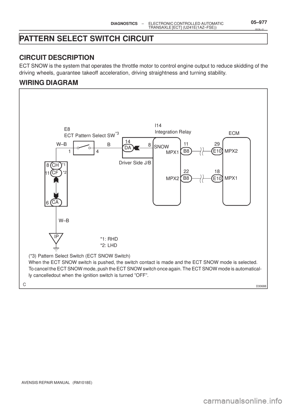
D30688
ECM
MPX2
MPX1 29
18 E10 11
B8
22 SNOWI14
Integration Relay
8
Driver Side J/B14
DA B E8
ECT Pattern Select SW
*1: RHD
*2: LHD 4 1 W±B
CH
CF
CA 8
11
6
W±B
IPE10 MPX1
MPX2
*1
*2
B8
(*3) Pattern Select Switch (ECT SNOW Switch)
When the ECT SNOW switch is pushed, the switch contact is made and the ECT SNOW mode is selected.
To cancel the ECT SNOW mode, push the ECT SNOW switch once again. The ECT SNOW mode is automatical-
ly cancelledout when the ignition switch is turned ºOFFº.
*3
± DIAGNOSTICSELECTRONIC CONTROLLED AUTOMATIC
TRANSAXLE [ECT] (U241E(1AZ±FSE))05±977
AVENSIS REPAIR MANUAL (RM1018E)
PATTERN SELECT SWITCH CIRCUIT
CIRCUIT DESCRIPTION
ECT SNOW is the system that operates the throttle motor to control engine output to reduce skidding of the
driving wheels, guarantee takeoff acceleration, driving straightness and turning stability.
WIRING DIAGRAM
05C9L±01
Page 1027 of 5135
![TOYOTA AVENSIS 2005 Service Repair Manual B59192
Wire Harness Side:
D30685
Switch Side:
05±978± DIAGNOSTICSELECTRONIC CONTROLLED AUTOMATIC
TRANSAXLE [ECT] (U241E(1AZ±FSE))
AVENSIS REPAIR MANUAL (RM1018E)
INSPECTION PROCEDURE
1 DRIVING TE TOYOTA AVENSIS 2005 Service Repair Manual B59192
Wire Harness Side:
D30685
Switch Side:
05±978± DIAGNOSTICSELECTRONIC CONTROLLED AUTOMATIC
TRANSAXLE [ECT] (U241E(1AZ±FSE))
AVENSIS REPAIR MANUAL (RM1018E)
INSPECTION PROCEDURE
1 DRIVING TE](/img/14/57441/w960_57441-1026.png)
B59192
Wire Harness Side:
D30685
Switch Side:
05±978± DIAGNOSTICSELECTRONIC CONTROLLED AUTOMATIC
TRANSAXLE [ECT] (U241E(1AZ±FSE))
AVENSIS REPAIR MANUAL (RM1018E)
INSPECTION PROCEDURE
1 DRIVING TEST
(a) Start the engine.
(b) Turn the ECT SNOW switch ºOFFº.
(c) Confirm vehicle response by driving from a parked position to fully depressing the accelerator pedal.
(d) Turn the ECT SNOW switch on and perform the same check as (c).
Confirm that there is a difference between ECT SNOW switch ºONº and ºOFFº.
HINT:
�Driving test should be done on a paved road (a nonskid road).
�Make sure not to use the TRAC system when testing a vehicle equipped with one.
Standard:
There is a difference in acceleration between ºONº and ºOFFº.
NG Go to step 2
OK
PROCEED TO NEXT CIRCUIT INSPECTION SHOWN ON PROBLEM SYMPTOMS TABLE
(See page xx±xxx)
2 CHECK HARNESS AND CONNECTOR(PATTERN SELECT SWITCH ASSY ± BODY
GROUND)
(a) Disconnect the connector of pattern select switch (ECT
SNOW switch).
(b) Measure the resistance between 4 of the wire harness
connector and body ground.
Standard:
Tester connectionSpecified condition
4 ± Body groundBelow 1 �
NG REPAIR OR REPLACE HARNESS AND
CONNECTOR
OK
3 INSPECT PATTERN SELECT SWITCH ASSY
(a) Measure the resistance between terminals 1 and 4 of pat-
tern select switch (ECT SNOW switch).
Standard:
Switch conditionTester connectionSpecified condition
Press continuously
Pattern select switch1 ± 4Continuity
Release
Pattern select switch1 ± 4No continuity
NG REPLACE PATTERN SELECT SWITCH ASSY
OK
Page 1028 of 5135
D30751
Instrument Panel J/B Assy
Vehicle Front Side:
DA
DA
SNOW
± DIAGNOSTICSELECTRONIC CONTROLLED AUTOMATIC
TRANSAXLE [ECT] (U241E(1AZ±FSE))05±979
AVENSIS REPAIR MANUAL (RM1018E)
4 CHECK HARNESS AND CONNECTOR(PATTERN SELECT SWITCH ASSY ±
INTEGRATION RELAY)
(a) Connect the connector of pattern select switch (ECT
SNOW switch).
(b) Disconnect the instrument panel J/B assy (integration
relay) connector.
(c) Measure the resistance between terminal SNOW of
instrument panel J/B assy (integration relay) and body
ground.
Standard:
Switch conditionTester connectionSpecified condition
Press continuously
Pattern select switchDA±14 (SNOW) ± Body
groundBelow 1 �
Release
Pattern select switchDA±14 (SNOW) ± Body
ground10 k� or higher
NG REPAIR OR REPLACE HARNESS AND
CONNECTOR
OK
PROCEED TO NEXT CIRCUIT INSPECTION SHOWN ON PROBLEM SYMPTOMS TABLE
(See page xx±xxx)
Page 1029 of 5135
05±972± DIAGNOSTICSELECTRONIC CONTROLLED AUTOMATIC
TRANSAXLE [ECT] (U241E(1AZ±FSE))
AVENSIS REPAIR MANUAL (RM1018E)
TRANSMISSION CONTROL SWITCH CIRCUIT
CIRCUIT DESCRIPTION
When shifting the shift lever into S position using the transmission control switch, it is possible to shift in 1
to 4 positions.
Shifting º+º once changes up 1 shift range position, º±º once changes down 1 shift range position respective-
ly.
05C9K±01
Page 1030 of 5135
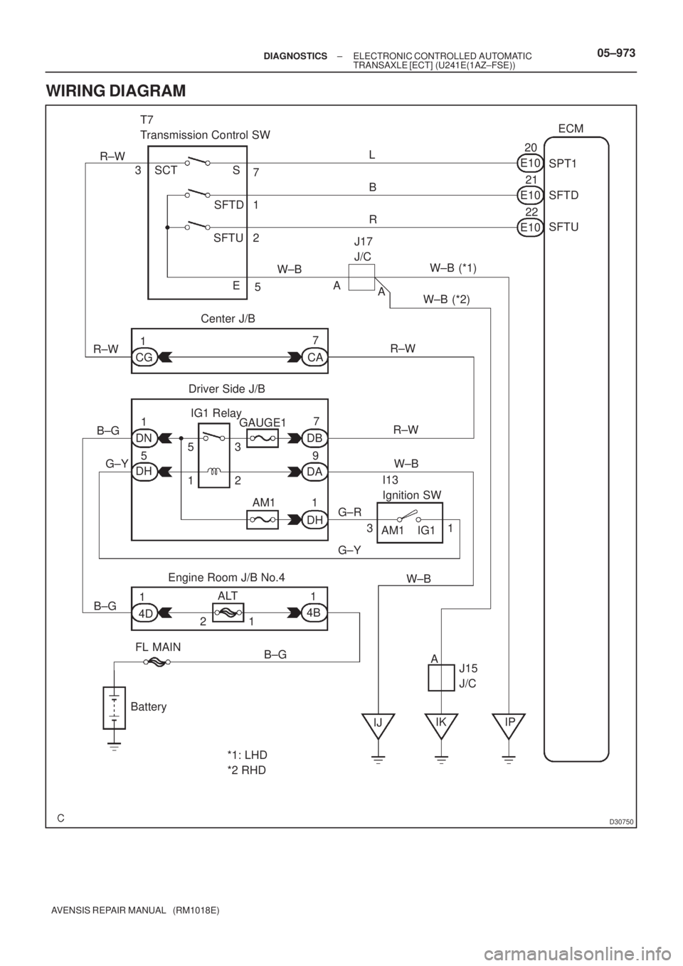
D30750
ECM
SPT1
SFTD
SFTU L
B
R20
21
22 E10
7
1
2
5J17
J/C
W±B(*1)
(*2) A
A S
SFTD
SFTU
E SCT 3 R±WT7
Transmission Control SW
Center J/B
Driver Side J/B
I13
Ignition SW
Engine Room J/B No.4
FL MAIN
Battery
*1: LHD
*2 RHDIJIK IPJ15
J/C A AM1 IG1R±W
W±B B±G
G±Y7
1
CA
7
DB
9
DA
1
DH AM1 GAUGE1 IG1 Relay
5
13
2 DN
31
1
4D1
4B ALT
21E10
E10
W±B
W±B
CG
R±W 1
5
DH
G±R
G±Y
W±B
B±G R±W
B±G
± DIAGNOSTICSELECTRONIC CONTROLLED AUTOMATIC
TRANSAXLE [ECT] (U241E(1AZ±FSE))05±973
AVENSIS REPAIR MANUAL (RM1018E)
WIRING DIAGRAM
Trending: jump cable, remote start, service schedule, SHOCK, seats, Abs sensor, odo

![TOYOTA AVENSIS 2005 Service Repair Manual 05CBZ±01
± DIAGNOSTICSELECTRONIC CONTROLLED AUTOMATIC
TRANSAXLE [ECT] (U341E)05±983
AVENSIS REPAIR MANUAL (RM1018E)
PRECAUTION
CAUTION:
Perform the RESET MEMORY (AT initialization) when replacing TOYOTA AVENSIS 2005 Service Repair Manual 05CBZ±01
± DIAGNOSTICSELECTRONIC CONTROLLED AUTOMATIC
TRANSAXLE [ECT] (U341E)05±983
AVENSIS REPAIR MANUAL (RM1018E)
PRECAUTION
CAUTION:
Perform the RESET MEMORY (AT initialization) when replacing](/img/14/57441/w960_57441-1021.png)

AVENSIS REPAIR MANUAL (RM1018E)
ELECTRONIC CONTROLLED AUTOMATIC TRANSAXLE
[ECT](U341E)
HOW TO PROCEED WITH TROU TOYOTA AVENSIS 2005 Service Repair Manual 0567N±10
05±980±
DIAGNOSTICS ELECTRONIC CONTROLLED AUTOMATIC
TRANSAXLE [ECT](U341E)
AVENSIS REPAIR MANUAL (RM1018E)
ELECTRONIC CONTROLLED AUTOMATIC TRANSAXLE
[ECT](U341E)
HOW TO PROCEED WITH TROU](/img/14/57441/w960_57441-1022.png)
![TOYOTA AVENSIS 2005 Service Repair Manual ±
DIAGNOSTICS ELECTRONIC CONTROLLED AUTOMATIC
TRANSAXLE [ECT] (U341E)05±981
AVENSIS REPAIR MANUAL (RM1018E)
10 Basic Inspection ( See page 40±2, 40±8 and 40±69 )
NG Go to step 19
OK
1 1 Mechan TOYOTA AVENSIS 2005 Service Repair Manual ±
DIAGNOSTICS ELECTRONIC CONTROLLED AUTOMATIC
TRANSAXLE [ECT] (U341E)05±981
AVENSIS REPAIR MANUAL (RM1018E)
10 Basic Inspection ( See page 40±2, 40±8 and 40±69 )
NG Go to step 19
OK
1 1 Mechan](/img/14/57441/w960_57441-1023.png)
![TOYOTA AVENSIS 2005 Service Repair Manual 05±982± DIAGNOSTICSELECTRONIC CONTROLLED AUTOMATIC
TRANSAXLE [ECT] (U341E)
AVENSIS REPAIR MANUAL (RM1018E)
19 Identification of Problem
20 Repair
21 Confirmation Test
End TOYOTA AVENSIS 2005 Service Repair Manual 05±982± DIAGNOSTICSELECTRONIC CONTROLLED AUTOMATIC
TRANSAXLE [ECT] (U341E)
AVENSIS REPAIR MANUAL (RM1018E)
19 Identification of Problem
20 Repair
21 Confirmation Test
End](/img/14/57441/w960_57441-1024.png)

![TOYOTA AVENSIS 2005 Service Repair Manual B59192
Wire Harness Side:
D30685
Switch Side:
05±978± DIAGNOSTICSELECTRONIC CONTROLLED AUTOMATIC
TRANSAXLE [ECT] (U241E(1AZ±FSE))
AVENSIS REPAIR MANUAL (RM1018E)
INSPECTION PROCEDURE
1 DRIVING TE TOYOTA AVENSIS 2005 Service Repair Manual B59192
Wire Harness Side:
D30685
Switch Side:
05±978± DIAGNOSTICSELECTRONIC CONTROLLED AUTOMATIC
TRANSAXLE [ECT] (U241E(1AZ±FSE))
AVENSIS REPAIR MANUAL (RM1018E)
INSPECTION PROCEDURE
1 DRIVING TE](/img/14/57441/w960_57441-1026.png)
![TOYOTA AVENSIS 2005 Service Repair Manual D30751
Instrument Panel J/B Assy
Vehicle Front Side:
DA
DA
SNOW
± DIAGNOSTICSELECTRONIC CONTROLLED AUTOMATIC
TRANSAXLE [ECT] (U241E(1AZ±FSE))05±979
AVENSIS REPAIR MANUAL (RM1018E)
4 CHECK HARNESS TOYOTA AVENSIS 2005 Service Repair Manual D30751
Instrument Panel J/B Assy
Vehicle Front Side:
DA
DA
SNOW
± DIAGNOSTICSELECTRONIC CONTROLLED AUTOMATIC
TRANSAXLE [ECT] (U241E(1AZ±FSE))05±979
AVENSIS REPAIR MANUAL (RM1018E)
4 CHECK HARNESS](/img/14/57441/w960_57441-1027.png)
![TOYOTA AVENSIS 2005 Service Repair Manual 05±972± DIAGNOSTICSELECTRONIC CONTROLLED AUTOMATIC
TRANSAXLE [ECT] (U241E(1AZ±FSE))
AVENSIS REPAIR MANUAL (RM1018E)
TRANSMISSION CONTROL SWITCH CIRCUIT
CIRCUIT DESCRIPTION
When shifting the shift TOYOTA AVENSIS 2005 Service Repair Manual 05±972± DIAGNOSTICSELECTRONIC CONTROLLED AUTOMATIC
TRANSAXLE [ECT] (U241E(1AZ±FSE))
AVENSIS REPAIR MANUAL (RM1018E)
TRANSMISSION CONTROL SWITCH CIRCUIT
CIRCUIT DESCRIPTION
When shifting the shift](/img/14/57441/w960_57441-1028.png)
