TOYOTA CAMRY 2000 Service Repair Manual
Manufacturer: TOYOTA, Model Year: 2000, Model line: CAMRY, Model: TOYOTA CAMRY 2000Pages: 4770, PDF Size: 86.41 MB
Page 4451 of 4770
Toyota Supports ASE CertificationPage 1 of 1
BO005±99
Title:
CAMRY CENTER CONSOLE LATCH
IMPROVEMENTS
Models:
'97±'99 Camry
Technical Service
BULLETIN
March 26, 1999
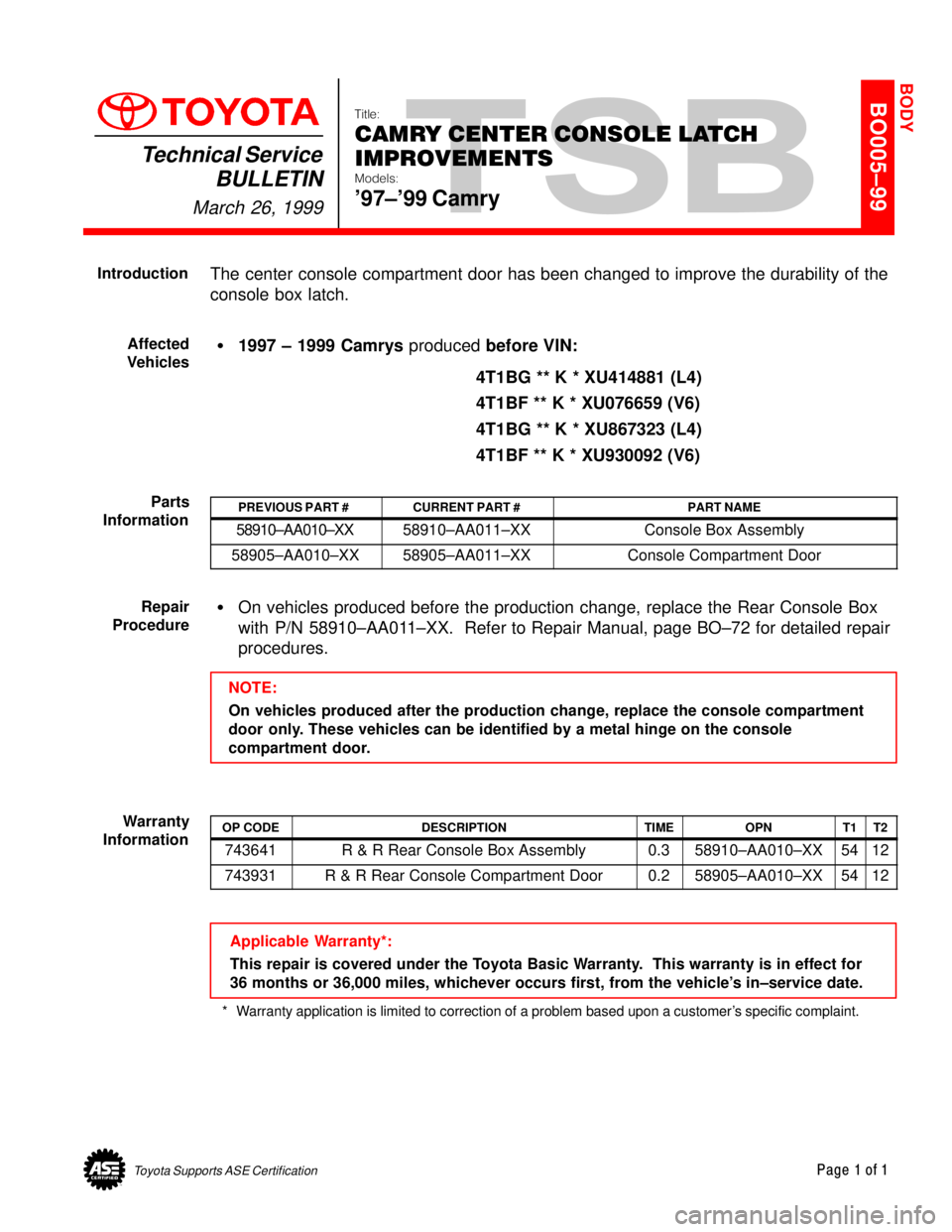
The center console compartment door has been changed to improve the durability of the
console box latch.
�1997 ± 1999 Camrys produced before VIN:
4T1BG ** K * XU414881 (L4)
4T1BF ** K * XU076659 (V6)
4T1BG ** K * XU867323 (L4)
4T1BF ** K * XU930092 (V6)
PREVIOUS PART #CURRENT PART #PART NAME
58910±AA010±XX58910±AA011±XXConsole Box Assembly
58905±AA010±XX58905±AA011±XXConsole Compartment Door
�On vehicles produced before the production change, replace the Rear Console Box
with P/N 58910±AA011±XX. Refer to Repair Manual, page BO±72 for detailed repair
procedures.
NOTE:
On vehicles produced after the production change, replace the console compartment
door only. These vehicles can be identified by a metal hinge on the console
compartment door.
OP CODEDESCRIPTIONTIMEOPNT1T2
743641R & R Rear Console Box Assembly0.358910±AA010±XX5412
743931R & R Rear Console Compartment Door0.258905±AA010±XX5412
Applicable Warranty*:
This repair is covered under the Toyota Basic Warranty. This warranty is in effect for
36 months or 36,000 miles, whichever occurs first, from the vehicle's in±service date.
* Warranty application is limited to correction of a problem based upon a customer's specific complaint.
BODY
Introduction
Affected
Vehicles
Parts
Information
Repair
Procedure
Warranty
Information
Page 4452 of 4770
Toyota Supports ASE CertificationPage 1 of 1
BO007±99
Title:
TMMK CAMRY/SIENNA HEADLIGHT
ALIGNMENT
Models:
'97±'99 Camry, '98±'99 Sienna
Technical Service
BULLETIN
April 16, 1999
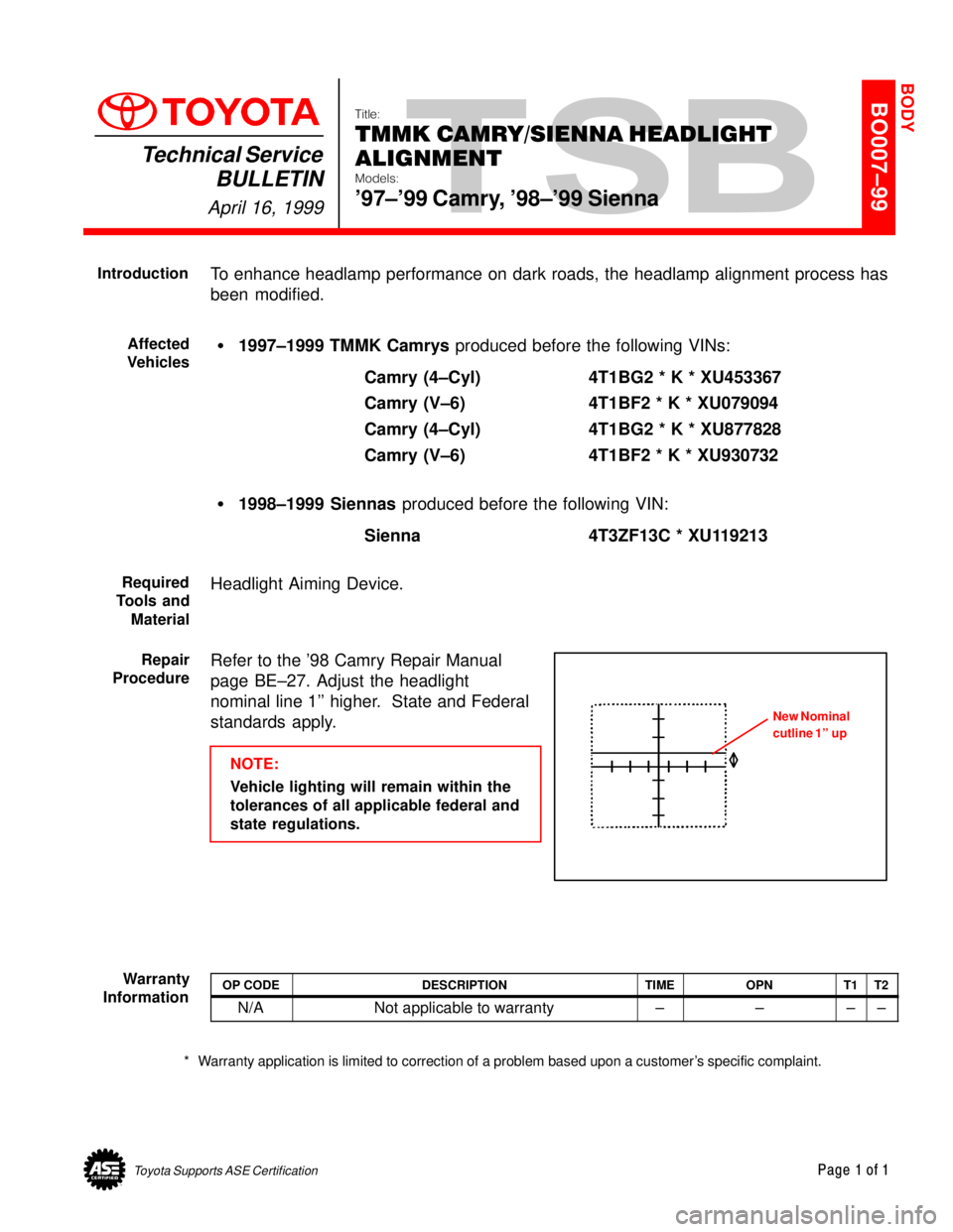
To enhance headlamp performance on dark roads, the headlamp alignment process has
been modified.
�1997±1999 TMMK Camrys produced before the following VINs:
Camry (4±Cyl) 4T1BG2 * K * XU453367
Camry (V±6) 4T1BF2 * K * XU079094
Camry (4±Cyl) 4T1BG2 * K * XU877828
Camry (V±6) 4T1BF2 * K * XU930732
�1998±1999 Siennas produced before the following VIN:
Sienna 4T3ZF13C * XU119213
Headlight Aiming Device.
Refer to the '98 Camry Repair Manual
page BE±27. Adjust the headlight
nominal line 1'' higher. State and Federal
standards apply.
NOTE:
Vehicle lighting will remain within the
tolerances of all applicable federal and
state regulations.
OP CODEDESCRIPTIONTIMEOPNT1T2
N/ANot applicable to warranty±±±±
* Warranty application is limited to correction of a problem based upon a customer's specific complaint.
BODY
Introduction
Affected
Vehicles
Required
Tools and
Material
Repair
Procedure
New Nominal
cutline 1'' up
Warranty
Information
Page 4453 of 4770

On some Toyota models, when Rapgard is removed from the vehicle, a stain is left on the paint
surface. This stain can be seen under the clear coat and is not a defect of the clear coat. The
stain corresponds to a wrinkled area of Rapgard which retained liquids, such as window washer
fluid, that left a discoloration.
REPAIR PROCEDURE:
To remove a stain from a vehicle, heat the stain surface to a temperature of 70�C ± 80�C.
When the stain is removed it will not reappear.
Equipment ±
1. Infrared lamp or dryer to heat the surface.
2. Aluminum foil or a damp cloth to protect plastic parts from deformation.
Procedure ±
1. Apply aluminum foil to adjoining plastic parts or cool with damp cloth periodically.
2. Use an infrared lamp or dryer on the stain developed area and heat for 5 to 10 minutes
at 70�C ± 80�C.
3. After heating for 5 minutes, check whether the stain has disappeared. If the stain still
remains, reheat the area and check again.
NOTE:Take care that the body's paint surface temperature does not become too high.
WARRANTY INFORMATION:
STAINS ON RAPGARD APPLIED AREASPage 1 of 1
AUGUST 9, 1996
BODY
BO008±96
ALL MODELS
OPCODE DESCRIPTION TIME OPN T1 T2
BD6004Remove stains from paint surface
caused by Rapguard0.653301±XXXXX 61 99
Stain
Page 4454 of 4770

Toyota Supports ASE CertificationPage 1 of 1
BO009±00
Title:
LOOSE CENTER HVAC VENT
ADJUSTMENT
Models:
'98 ± '99 CBU Camry
Technical Service
BULLETIN
April 28, 2000
TSB Revision Notice:
The information updated in this TSB is red
and underlined.
A repair procedure has been made available to remedy customer complaints regarding
loose vertical adjustment of the center vents on 1998 ± 1999 CBU Camry.
�1998 through 1999 model year Japan built Camry.
MODEL/PLANTSTARTING VIN
2000 MY Japan Built CamryJT2BG2*K*X03390182000 MY Japan Built CamryJT2BF2*K*X0200364
PART NUMBERPART NUMBERQUANTITY
90202±05129Washer2
1. Remove the left vent barrel by gently
prying using a wide flat tool with
smooth edges. Be careful not to
damage the vent assembly.
2. Install a washer (P/N 90202±05129
)
on the shaft inside the vent duct.
3. Reinstall the vent barrel by carefully
pushing it into position until it locks
onto the shafts on the sides of the
duct. Be sure the spacer and/or
washer do not fall down into the vent
duct.
NOTE:
The spacer (P/N 55682±12140) can be
ordered, if lost.
4. Confirm that the vent vertical
adjustment is tighter and moves
smoothly.
5. Repeat steps 1 through 4
for the right
center vent.
OP CODEDESCRIPTIONTIMEOPNT1T2
BD0025Remove & Reinstall Vent Barrels0.255660±33080±XX4014
Applicable Warranty*:
This repair is covered under the Toyota Basic Warranty. This warranty is in effect for
36 months or 36,000 miles, whichever occurs first, from the vehicle's in±service date.
* Warranty application is limited to correction of a problem based upon a customer's specific complaint.
BODY
Introduction
Applicable
Vehicles
Production
Change
Information
Parts
Information
Vent DuctCenter Vent Assembly
Vent Barrel Install Washer (P/N 90202±05129
)
on Shaft Inside Vent Duct
Repair
Procedure
Side View of Vent Barrel Install
Spacer
Here
Spacer
(P/N 55682±12140)
Warranty
Information
Page 4455 of 4770
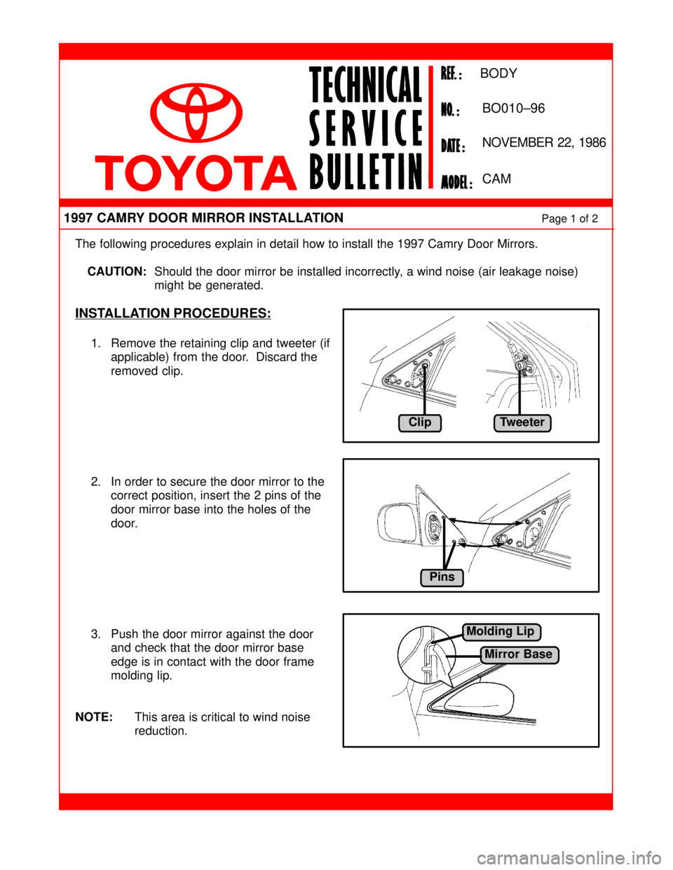
The following procedures explain in detail how to install the 1997 Camry Door Mirrors.
CAUTION:Should the door mirror be installed incorrectly, a wind noise (air leakage noise)
might be generated.
INSTALLATION PROCEDURES:
1. Remove the retaining clip and tweeter (if
applicable) from the door. Discard the
removed clip.
2. In order to secure the door mirror to the
correct position, insert the 2 pins of the
door mirror base into the holes of the
door.
3. Push the door mirror against the door
and check that the door mirror base
edge is in contact with the door frame
molding lip.
NOTE:This area is critical to wind noise
reduction.
1997 CAMRY DOOR MIRROR INSTALLATIONPage 1 of 2
NOVEMBER 22, 1986
BODY
BO010±96
CAM
ClipTweeter
Pins
Molding Lip
Mirror Base
Page 4456 of 4770
1997 CAMRY DOOR MIRROR INSTALLATIONPage 2 of 2
INSTALLATION PROCEDURES (Cont'd):
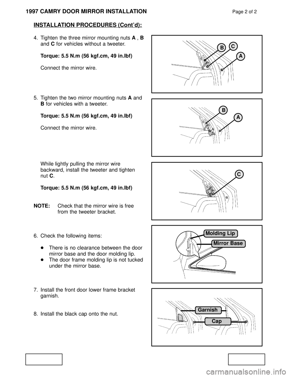
4. Tighten the three mirror mounting nuts A , B
and C for vehicles without a tweeter.
Torque: 5.5 N.m (56 kgf.cm, 49 in.lbf)
Connect the mirror wire.
5. Tighten the two mirror mounting nuts A and
B for vehicles with a tweeter.
Torque: 5.5 N.m (56 kgf.cm, 49 in.lbf)
Connect the mirror wire.
While lightly pulling the mirror wire
backward, install the tweeter and tighten
nut C.
Torque: 5.5 N.m (56 kgf.cm, 49 in.lbf)
NOTE:Check that the mirror wire is free
from the tweeter bracket.
6. Check the following items:
�There is no clearance between the door
mirror base and the door molding lip.
�The door frame molding lip is not tucked
under the mirror base.
7. Install the front door lower frame bracket
garnish.
8. Install the black cap onto the nut.
BC
A
B
A
C
Molding Lip
Mirror Base
Garnish
Cap
Page 4457 of 4770
Toyota Supports ASE CertificationPage 1 of 9
BO010-02Title:
CHILD RESTRAINT SEAT TOP STRAP
BRACKET INSTALLATION
Models:
'83 ± '00 All Models
Technical Service
BULLETIN
May 24, 2002
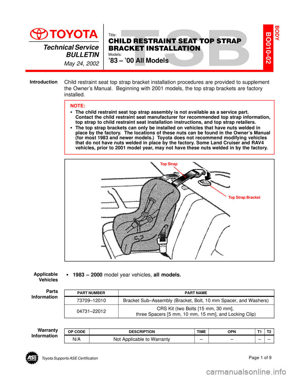
Child restraint seat top strap bracket installation procedures are provided to supplement
the Owner's Manual. Beginning with 2001 models, the top strap brackets are factory
installed.
NOTE:
�The child restraint seat top strap assembly is not available as a service part.
Contact the child restraint seat manufacturer for recommended top strap information,
top strap to child restraint seat installation instructions, and top strap retailers.
�The top strap brackets can only be installed on vehicles that have nuts welded in
place by the factory. The locations of these nuts can be found in the Owner's Manual
(for most 1983 and newer models.) Toyota does not recommend modifying vehicles
that do not have nuts welded in place by the factory. Some Land Cruiser and RAV4
vehicles, prior to 2001 model year, may not have these nuts welded in by the factory.
Top Strap
Top Strap Bracket
�1983 ± 2000 model year vehicles, all models.
PART NUMBERPART NAME
73709±12010Bracket Sub±Assembly (Bracket, Bolt, 10 mm Spacer, and Washers)
04731±22012CRS Kit (two Bolts [15 mm, 30 mm],
three Spacers [5 mm, 10 mm, 15 mm], and Locking Clip)
OP CODEDESCRIPTIONTIMEOPNT1T2
N/ANot Applicable to Warranty±±±±
BODY
Introduction
Applicable
Vehicles
Parts
Information
Warranty
Information
Page 4458 of 4770
CHILD RESTRAINT SEAT TOP STRAP BRACKET INSTALLATION ± BO010-02May 24, 2002
Page 2 of 9
Child Restraint Seat Top Strap Bracket Installation
Obtain the exact year and vehicle model Toyota Owner's Manual before beginning
installation.
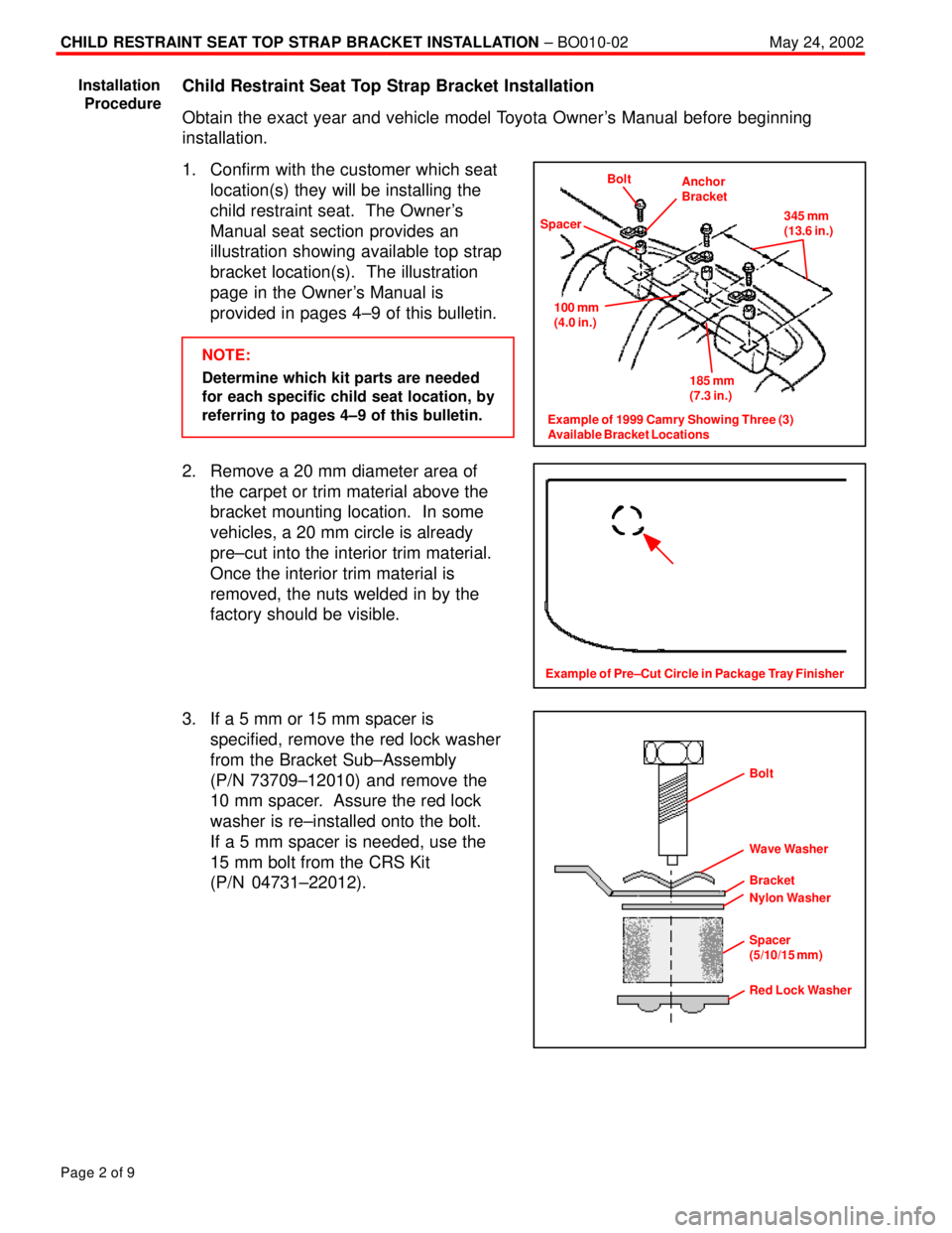
1. Confirm with the customer which seat
location(s) they will be installing the
child restraint seat. The Owner's
Manual seat section provides an
illustration showing available top strap
bracket location(s). The illustration
page in the Owner's Manual is
provided in pages 4±9 of this bulletin.
NOTE:
Determine which kit parts are needed
for each specific child seat location, by
referring to pages 4±9 of this bulletin.
2. Remove a 20 mm diameter area of
the carpet or trim material above the
bracket mounting location. In some
vehicles, a 20 mm circle is already
pre±cut into the interior trim material.
Once the interior trim material is
removed, the nuts welded in by the
factory should be visible.
3. If a 5 mm or 15 mm spacer is
specified, remove the red lock washer
from the Bracket Sub±Assembly
(P/N 73709±12010) and remove the
10 mm spacer. Assure the red lock
washer is re±installed onto the bolt.
If a 5 mm spacer is needed, use the
15 mm bolt from the CRS Kit
(P/N 04731±22012).
Installation
Procedure
Bolt
Spacer
100 mm
(4.0 in.)
Anchor
Bracket
185 mm
(7.3 in.)345 mm
(13.6 in.)
Example of 1999 Camry Showing Three (3)
Available Bracket Locations
Example of Pre±Cut Circle in Package Tray Finisher
Red Lock Washer Bolt
Wave Washer
Bracket
Nylon Washer
Spacer
(5/10/15 mm)
Page 4459 of 4770
CHILD RESTRAINT SEAT TOP STRAP BRACKET INSTALLATION ± BO010-02May 24, 2002
Page 3 of 9
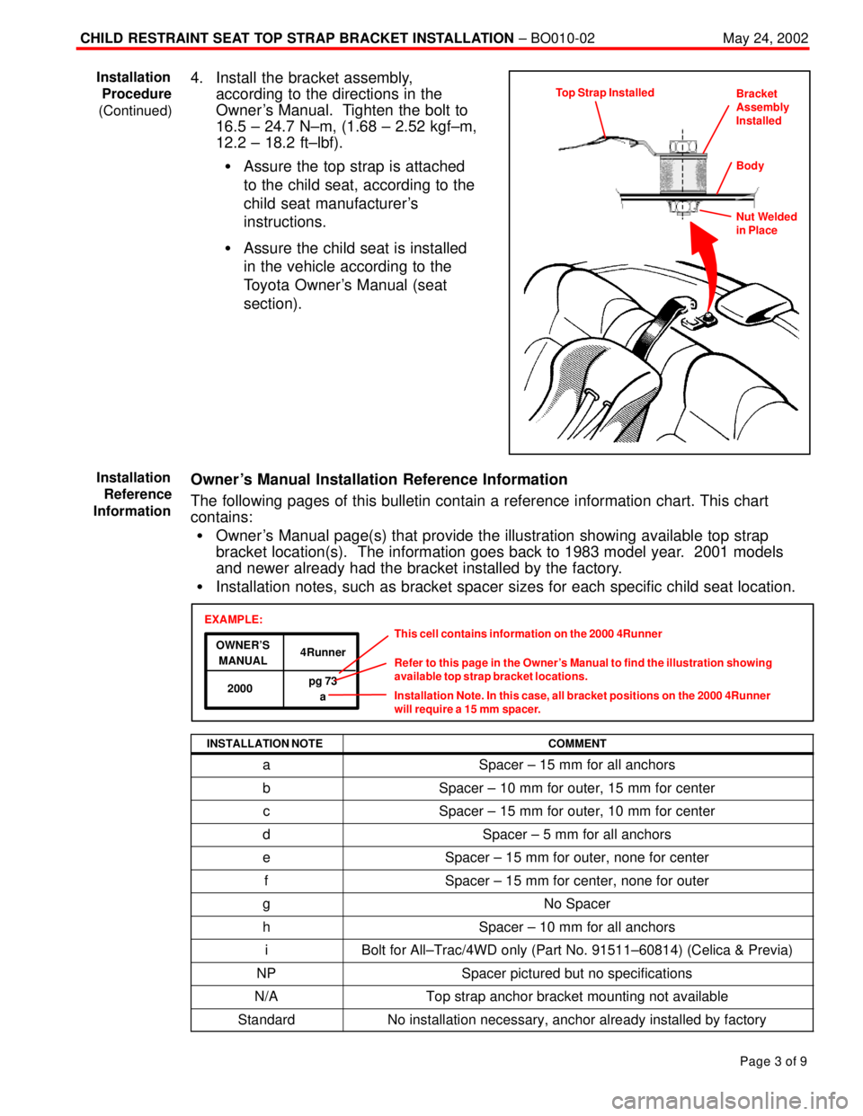
4. Install the bracket assembly,
according to the directions in the
Owner 's Manual. Tighten the bolt to
16.5 ± 24.7 N±m, (1.68 ± 2.52 kgf±m,
12.2 ± 18.2 ft±lbf).
�Assure the top strap is attached
to the child seat, according to the
child seat manufacturer's
instructions.
�Assure the child seat is installed
in the vehicle according to the
Toyota Owner's Manual (seat
section).
Owner 's Manual Installation Reference Information
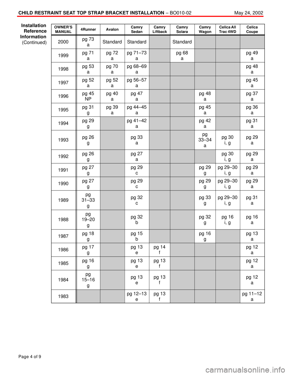
The following pages of this bulletin contain a reference information chart. This chart
contains:
�Owner 's Manual page(s) that provide the illustration showing available top strap
bracket location(s). The information goes back to 1983 model year. 2001 models
and newer already had the bracket installed by the factory.
�Installation notes, such as bracket spacer sizes for each specific child seat location.
OWNER'S
MANUAL4Runner
pg 73
a 2000This cell contains information on the 2000 4Runner
Refer to this page in the Owner's Manual to find the illustration showing
available top strap bracket locations.
Installation Note. In this case, all bracket positions on the 2000 4Runner
will require a 15 mm spacer.
EXAMPLE:
INSTALLATION NOTE
COMMENT
aSpacer ± 15 mm for all anchors
bSpacer ± 10 mm for outer, 15 mm for center
cSpacer ± 15 mm for outer, 10 mm for center
dSpacer ± 5 mm for all anchors
eSpacer ± 15 mm for outer, none for center
fSpacer ± 15 mm for center, none for outer
gNo Spacer
hSpacer ± 10 mm for all anchors
iBolt for All±Trac/4WD only (Part No. 91511±60814) (Celica & Previa)
NPSpacer pictured but no specifications
N/ATop strap anchor bracket mounting not available
StandardNo installation necessary, anchor already installed by factory
Bracket
Assembly
InstalledTop Strap Installed
Nut Welded
in Place Body
Installation
Procedure
(Continued)
Installation
Reference
Information
Page 4460 of 4770
CHILD RESTRAINT SEAT TOP STRAP BRACKET INSTALLATION ± BO010-02May 24, 2002
Page 4 of 9
OWNER'S
MANUAL4RunnerAvalonCamry
SedanCamry
LiftbackCamry
SolaraCamry
WagonCelica All
Trac 4WDCelica
Coupe
2000pg 73
aStandardStandardStandard
1999pg 71
apg 72
apg 71±73
apg 68
apg 49
a
1998pg 53
apg 70
apg 68±69
apg 48
a
1997pg 52
apg 52
apg 56±57
apg 45
a
1996pg 45
NPpg 40
apg 47
apg 48
apg 37
a
1995pg 31
gpg 39
apg 44±45
apg 45
apg 36
a
1994pg 29
gpg 41±42
apg 42
apg 31
a
1993pg 26
gpg 33
apg
33±34
apg 30
i, gpg 29
a
1992pg 26
gpg 27
apg 30
i, gpg 29
a
1991pg 27
gpg 29
cpg 29
gpg 29±30
i, gpg 29
a
1990pg 27
gpg 29
cpg 29
gpg 29±30
i, gpg 29
a
1989
pg
31±33
gpg 32
cpg 33
gpg 29±30
i, gpg 31
a
1988
pg
19±20
gpg 32
bpg 32
gpg 16
i, gpg 16
a
1987pg 18
gpg 15
bpg 16
gpg 13
a
1986pg 17
gpg 13
epg 14
fpg 12
a
1985pg 16
gpg 13
epg 13
fpg 12
a
1984
pg
15±16
gpg 13
epg 13
fpg 12
a
1983pg 12±13
epg 13
fpg 11±12
a
Installation
Reference
Information
(Continued)