stop start TOYOTA CAMRY 2009 XV40 / 8.G Service Manual
[x] Cancel search | Manufacturer: TOYOTA, Model Year: 2009, Model line: CAMRY, Model: TOYOTA CAMRY 2009 XV40 / 8.GPages: 480, PDF Size: 6.44 MB
Page 280 of 480

280 3-6. Other interior features
■The power outlet can be used when
Vehicles with smart key system
The “ENGINE START STOP” switch is in ACCESSORY or IGNITION ON
mode.
Vehicles without smart key system
The engine switch is in the “ACC” or “ON” position.
■ Cable pass-through
Connected cables can be passed through the hole in the auxiliary box to the
front passenger’s side of the auxiliary box. ( →P. 274)
NOTICE
■To avoid damaging the power outlet
Close the power outlet lid when the power outlet is not in use.
Foreign objects or liquids that enter the power outlet may cause a short cir-
cuit.
■ To prevent the fuse from being blown
Do not use an accessory that uses more than 12 V 10 A.
■ To prevent the battery from being discharged
Do not use the power outlet longer than necessary when the engine is not
running.
Page 281 of 480
281
3-6. Other interior features
3
Interior features
Seat heaters (if equipped)
■The seat heaters can be used when
Vehicles with smart key system
The “ENGINE START STOP” switch is in IGNITION ON mode.
Vehicles without smart key system
The engine switch is in “ON” position.
■ When not in use
Turn the seat heater off. The indicator light turns off.
CAUTION
■Burns
●Use caution when seating the following persons in a seat with the seat
heater on to avoid the possibility of burns:
• Babies, small children, the elderly, the sick and the disabled
• Persons with sensitive skin
• Persons who are fatigued
• Persons who have taken alcohol or drugs that induce sleep (sleeping
drugs, cold remedies, etc.)
● Do not cover the seat with anything when using the seat heater.
Using the seat heater with a blanket or cushion increases the temperature
of the seat and may lead to overheating.
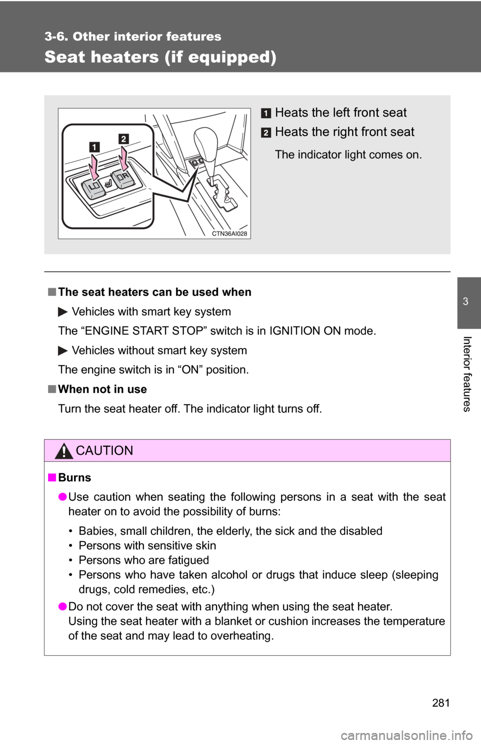
Heats the left front seat
Heats the right front seat
The indicator light comes on.
Page 311 of 480
311
4-3. Do-it-yourself maintenance
4
Maintenance and care
CAUTION
The engine compartment contains many mechanisms and fluids that may
move suddenly, become hot, or become electrically energized. To avoid death
or serious injury observe the following precautions.
■
When working on the engine compartment
●Keep hands, clothing, and tools away from the moving fan and engine
drive belt.
● Be careful not to touch the engine, radiator, exhaust manifold, etc. right
after driving as they may be hot. Oil and other fluids may also be hot.
● Do not leave anything that may burn easily, such as paper or rags, in the
engine compartment.
● Do not smoke, cause sparks or expose an open flame to fuel or the bat-
tery. Fuel and battery fumes are flammable.
● Be extremely cautious when working on the battery. It contains poisonous
and corrosive sulfuric acid.
● Take care because brake fluid can harm your hands or eyes and damage
painted surfaces.
If fluid gets on your hands or in your eyes, flush the affected area with
clean water immediately.
If you still experience discomfort, see a doctor.
■ When working near the electric c ooling fans or radiator grille
Vehicles with smart key system: Be sure the “ENGINE START STOP” switch
is OFF. With the “ENGINE START STOP” switch in IGNITION ON mode, the
electric cooling fans may automatically start to run if the air conditioning is on
and/or the coolant temperature is high. ( →P. 326)
Vehicles without smart key system: Be sure the engine switch is OFF. With
the engine switch in “ON” position, the electric cooling fans may automati-
cally start to run if the air conditioning is on and/or the coolant temperature is
high. ( →P. 326)
■ Safety glasses
Wear safety glasses to prevent flying or falling material, fluid spray, etc. from
getting in the eyes.
Page 315 of 480
315
4-3. Do-it-yourself maintenance
4
Maintenance and care
CAUTION
■
When raising your vehicle
Make sure to observe the following to reduce the possibility of death or seri-
ous injury.
●Do not use the jack that was supplied with your vehicle.
● Do not put any part of your body or get underneath the vehicle supported
only by the floor jack.
Always use automotive jack stands on a solid, level surface.
● Do not start the engine while the vehicle is supported by the floor jack.
● Stop the vehicle on level firm ground, firmly set the parking brake and put
the shift lever in P (automatic transmission) or R (manual transmission).
● Make sure to set the floor jack properly at the jack point.
Raising the vehicle with an improperly positioned floor jack will damage
the vehicle and may cause the vehicle to fall off the floor jack.
● Do not raise the vehicle while someone is in the vehicle.
● When raising the vehicle, do not place any objects on top of or underneath
the floor jack.
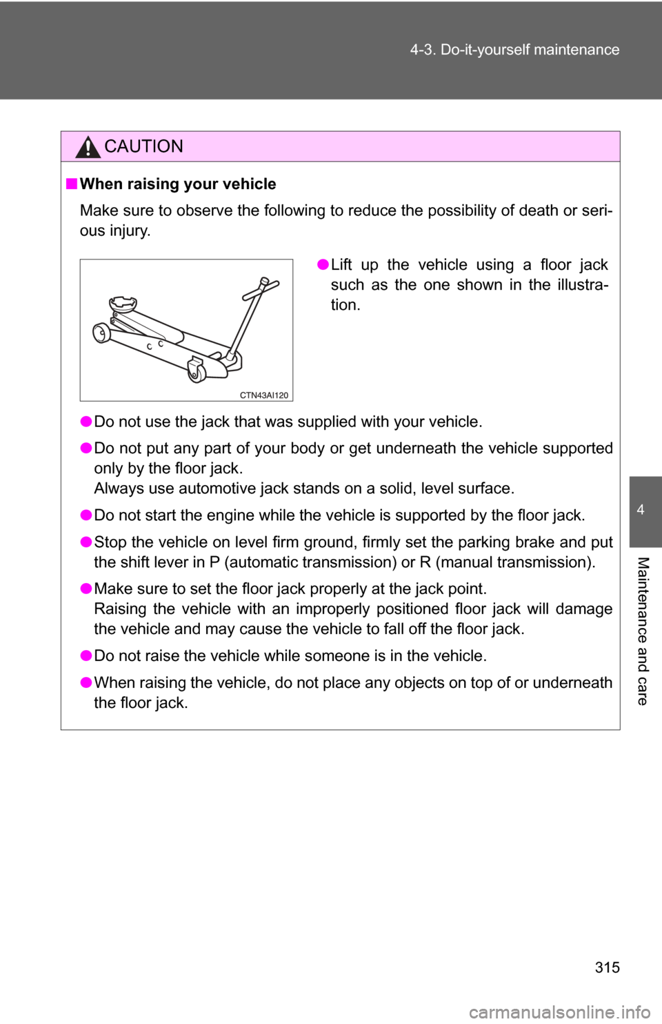
●Lift up the vehicle using a floor jack
such as the one shown in the illustra-
tion.
Page 323 of 480

323
4-3. Do-it-yourself maintenance
4
Maintenance and care
■
Engine oil consumption
●The amount of engine oil consumed depends on the oil viscosity, the
quality of the oil and the way the vehicle is driven.
● More oil is consumed under driving conditions such as high speeds and
frequent acceleration and deceleration.
● A new engine consumes more oil.
● When judging the amount of oil consumption, keep in mind that the oil
may have become diluted, making it difficult to judge the true level accu-
rately.
● Oil consumption: Max. 1.1 qt./600 miles, 0.9 lmp.qt./600 miles (1.0 L per
1000 km)
● If you consume more than 1.1 qt. (1.0 L, 0.9 lmp.qt.) every 600 miles
(1000 km), contact your Toyota dealer.
■ After changing the engine oil (U.S.A. only)
To reset the oil change system, follow the procedure below:
Turn the “ENGINE START STOP” switch or engine switch OFF with
the trip meter A reading shown. ( →P. 149)
While pressing the trip meter reset button ( →P. 141), turn the
“ENGINE START STOP” switch or engine switch ON.
Without multi-information display
Continue to press and hold the knob until the trip meter displays
000000.
With multi-information display Continue to press and hold the knob until “COMPLETE” appears on
the multi-information display.
STEP1
STEP2
STEP3
STEP3
Page 336 of 480

336 4-3. Do-it-yourself maintenance
Installing tire pressure warning valves and transmittersWhen replacing tires or wheels, tire pressure warning valves and
transmitters must also be installed.
When new tire pressure warning valves and transmitters are
installed, new tire pressure warning valve and transmitter ID codes
must be registered in the tire pressure warning computer and the tire
pressure warning system must be initialized. Have tire pressure
warning valve and transmitter ID codes registered by your Toyota
dealer. ( →P. 337)
Initializing the tire pressure warning system
■ The tire pressure warning system must be initialized when
inflation the tire pressure is changed (such as when changing
traveling speed or load weight.)
When the tire pressure warning syst em is initialized, the current tire
inflation pressure is set as the pressure benchmark.
■ How to initialize the tire pressure warning system
Park the vehicle in a safe place and turn the “ENGINE START
STOP” switch or the engine switch OFF.
While the vehicle is moving, in itialization is not performed.
Adjust the tire inflation pressure to the specified cold tire infla-
tion pressure level. ( →P. 436)
Make sure to adjust the tire pressure to the specified cold tire
inflation pressure level. The tire pressure warning system will
operate based on this pressure level.
Turn the “ENGINE START STOP” switch to IGNITION ON
mode (vehicles with smart key system) or engine switch to
“ON” position (vehicles without smart key system).
STEP1
STEP2
STEP3
Page 337 of 480
337
4-3. Do-it-yourself maintenance
4
Maintenance and care
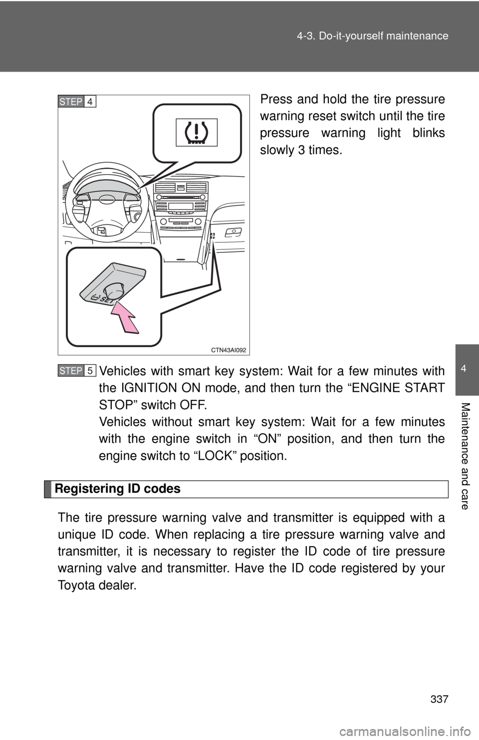
Press and hold the tire pressure
warning reset switch until the tire
pressure warning light blinks
slowly 3 times.
Vehicles with smart key system: Wait for a few minutes with
the IGNITION ON mode, and then turn the “ENGINE START
STOP” switch OFF.
Vehicles without smart key system: Wait for a few minutes
with the engine switch in “ON” position, and then turn the
engine switch to “LOCK” position.
Registering ID codes The tire pressure warning valve and transmitter is equipped with a
unique ID code. When replacing a tire pressure warning valve and
transmitter, it is necessary to regi ster the ID code of tire pressure
warning valve and transmitter. Have the ID code registered by your
Toyota dealer.
STEP4
STEP5
Page 350 of 480
350
4-3. Do-it-yourself maintenance
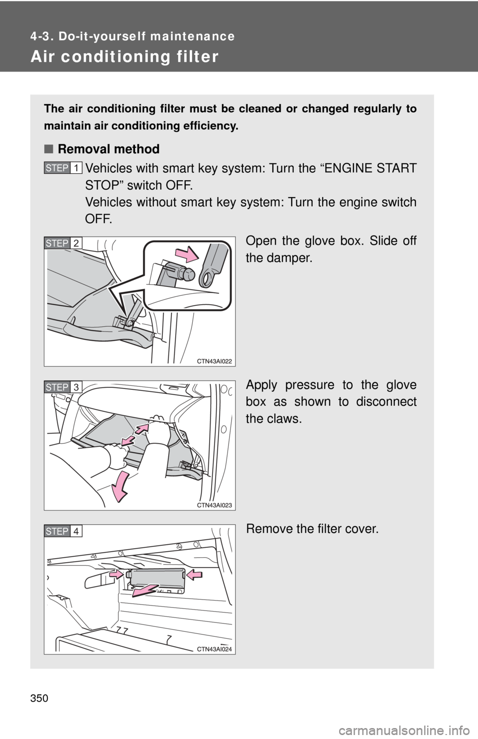
Air conditioning filter
The air conditioning filter must be cleaned or changed regularly to
maintain air conditioning efficiency.
■ Removal method
Vehicles with smart key system: Turn the “ENGINE START
STOP” switch OFF.
Vehicles without smart key sy stem: Turn the engine switch
OFF.
Open the glove box. Slide off
the damper.
Apply pressure to the glove
box as shown to disconnect
the claws.
Remove the filter cover.
STEP1
STEP2
STEP3
STEP4
Page 357 of 480
357
4-3. Do-it-yourself maintenance
4
Maintenance and care
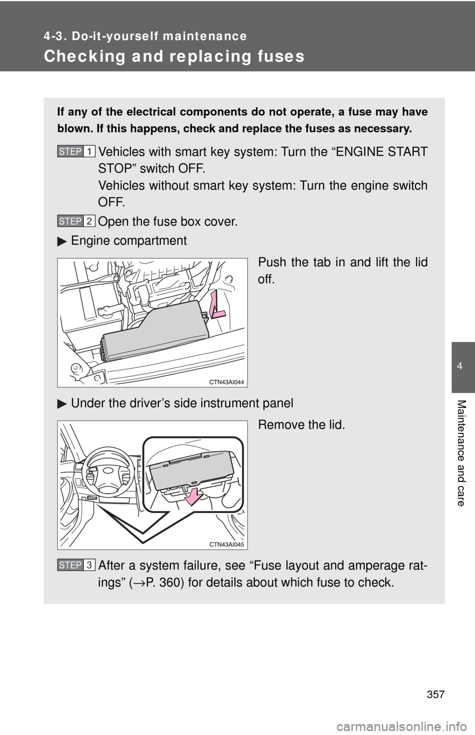
Checking and replacing fuses
If any of the electrical components do not operate, a fuse may have
blown. If this happens, check and replace the fuses as necessary.
Vehicles with smart key system: Turn the “ENGINE START
STOP” switch OFF.
Vehicles without smart key system: Turn the engine switch
OFF.
Open the fuse box cover.
Engine compartment
Push the tab in and lift the lid
off.
Under the driver’s side instrument panel Remove the lid.
After a system failure, see “Fuse layout and amperage rat-
ings” ( →P. 360) for details about which fuse to check.STEP1
STEP2
STEP3
Page 364 of 480
364 4-3. Do-it-yourself maintenance
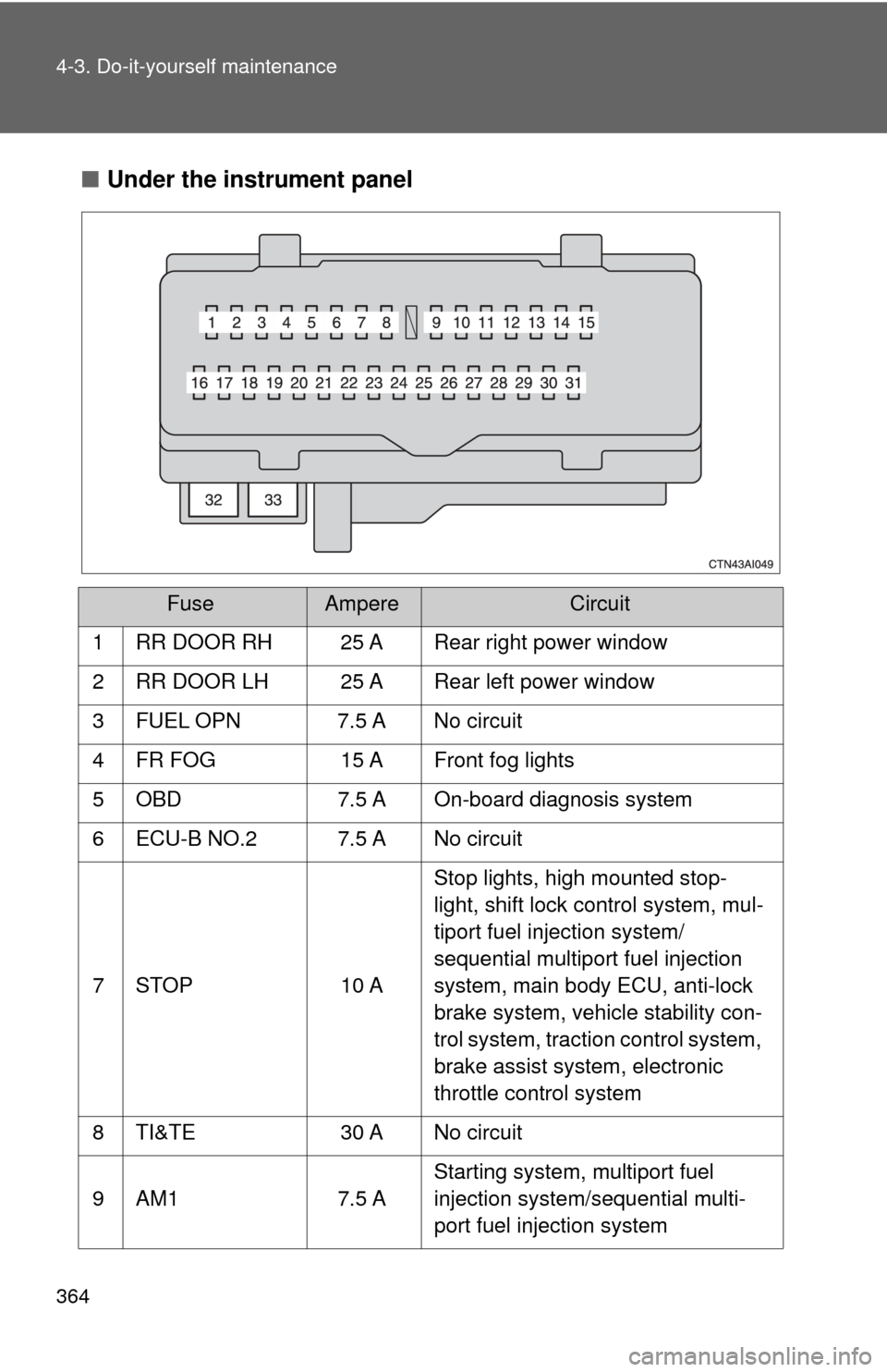
■Under the instrument panel
FuseAmpereCircuit
1 RR DOOR RH 25 A Rear right power window
2 RR DOOR LH 25 A Rear left power window
3 FUEL OPN 7.5 A No circuit
4 FR FOG 15 A Front fog lights
5 OBD 7.5 A On-board diagnosis system
6 ECU-B NO.2 7.5 A No circuit
7 STOP 10 A Stop lights, high mounted stop-
light, shift lock control system, mul-
tiport fuel injection system/
sequential multiport fuel injection
system, main body ECU, anti-lock
brake system, vehicle stability con-
trol system, traction control system,
brake assist system, electronic
throttle control system
8 TI&TE 30 A No circuit
9 AM1 7.5 A Starting system, multiport fuel
injection system/sequential multi-
port fuel injection system