check engine TOYOTA CAMRY V20 1986 Service Information
[x] Cancel search | Manufacturer: TOYOTA, Model Year: 1986, Model line: CAMRY V20, Model: TOYOTA CAMRY V20 1986Pages: 2389, PDF Size: 84.44 MB
Page 1273 of 2389
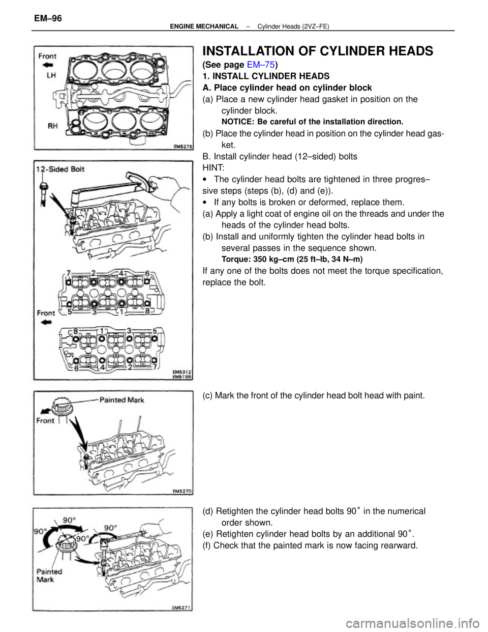
INSTALLATION OF CYLINDER HEADS
(See page EM±75)
1. INSTALL CYLINDER HEADS
A. Place cylinder head on cylinder block
(a) Place a new cylinder head gasket in position on the
cylinder block.
NOTICE: Be careful of the installation direction.
(b) Place the cylinder head in position on the cylinder head gas-
ket.
B. Install cylinder head (12±sided) bolts
HINT:
wThe cylinder head bolts are tightened in three progres±
sive steps (steps (b), (d) and (e)).
wIf any bolts is broken or deformed, replace them.
(a) Apply a light coat of engine oil on the threads and under the
heads of the cylinder head bolts.
(b) Install and uniformly tighten the cylinder head bolts in
several passes in the sequence shown.
Torque: 350 kg±cm (25 ft±lb, 34 N±m)
If any one of the bolts does not meet the torque specification,
replace the bolt.
(d) Retighten the cylinder head bolts 90° in the numerical
order shown.
(e) Retighten cylinder head bolts by an additional 90°.
(f) Check that the painted mark is now facing rearward. (c) Mark the front of the cylinder head bolt head with paint.
± ENGINE MECHANICALCylinder Heads (2VZ±FE)EM±96
Page 1278 of 2389
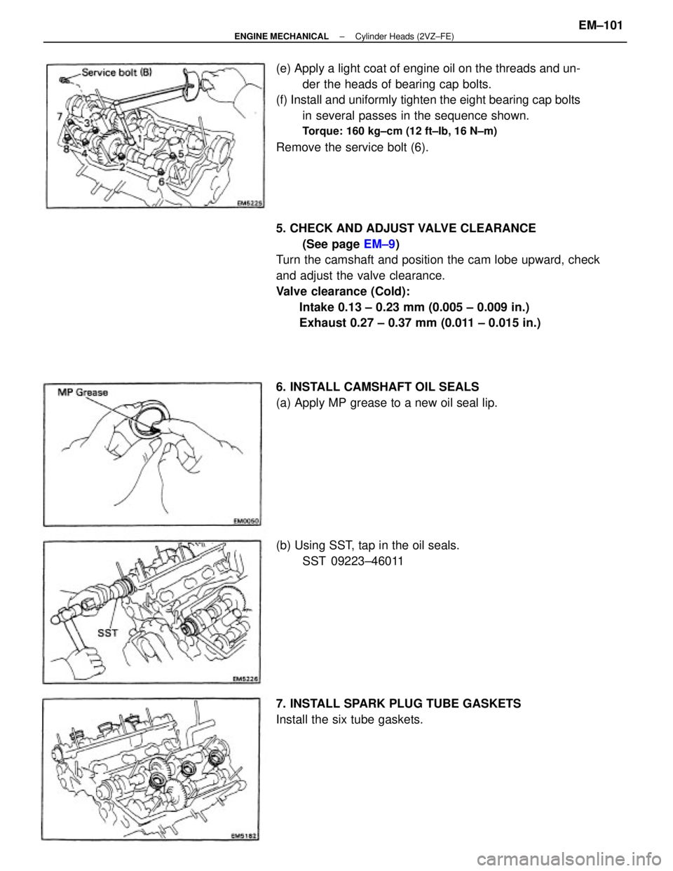
5. CHECK AND ADJUST VALVE CLEARANCE
(See page EM±9)
Turn the camshaft and position the cam lobe upward, check
and adjust the valve clearance.
Valve clearance (Cold):
Intake 0.13 ± 0.23 mm (0.005 ± 0.009 in.)
Exhaust 0.27 ± 0.37 mm (0.011 ± 0.015 in.) (e) Apply a light coat of engine oil on the threads and un-
der the heads of bearing cap bolts.
(f) Install and uniformly tighten the eight bearing cap bolts
in several passes in the sequence shown.
Torque: 160 kg±cm (12 ft±Ib, 16 N±m)
Remove the service bolt (6).
6. INSTALL CAMSHAFT OIL SEALS
(a) Apply MP grease to a new oil seal lip.
7. INSTALL SPARK PLUG TUBE GASKETS
Install the six tube gaskets. (b) Using SST, tap in the oil seals.
SST 09223±46011
± ENGINE MECHANICALCylinder Heads (2VZ±FE)EM±101
Page 1283 of 2389
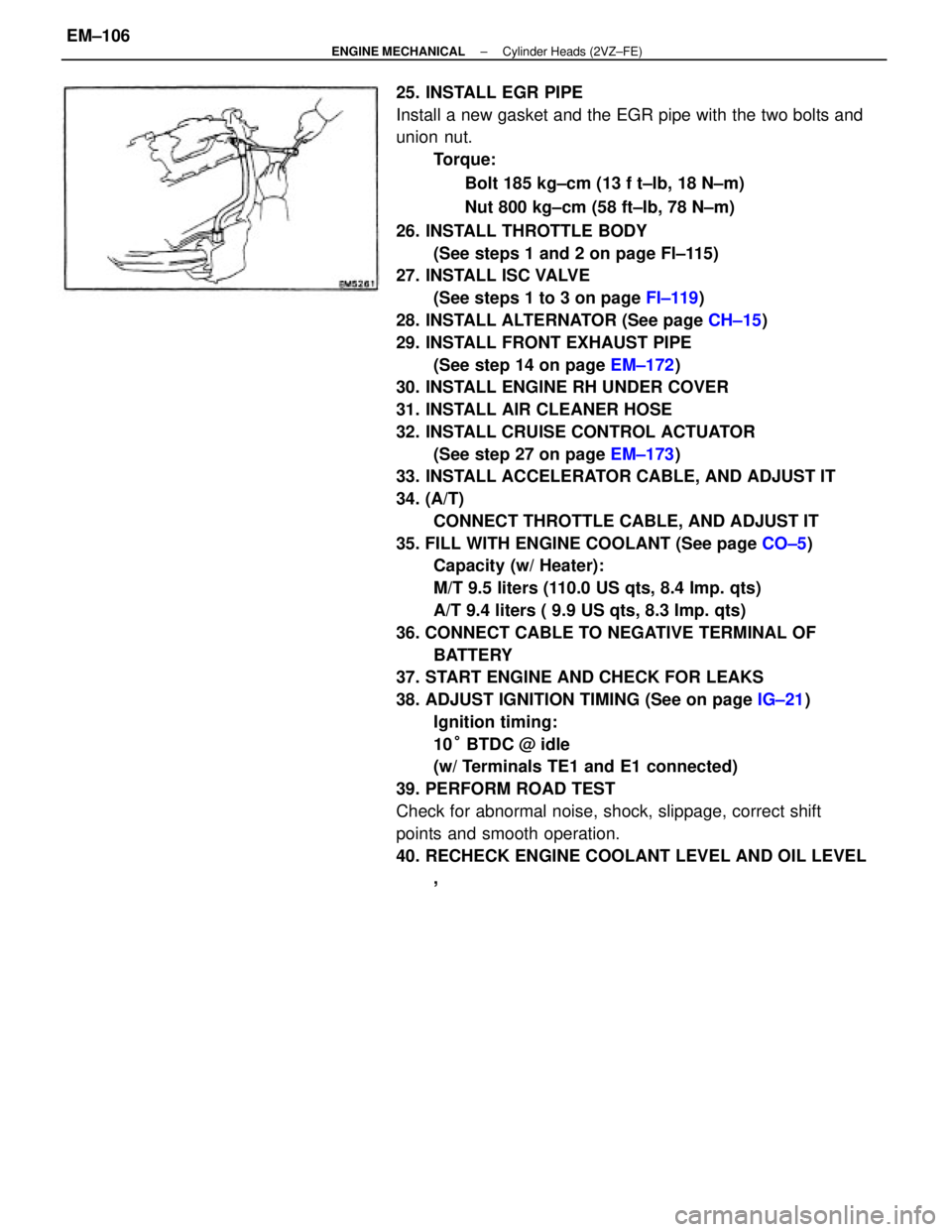
25. INSTALL EGR PIPE
Install a new gasket and the EGR pipe with the two bolts and
union nut.
Torque:
Bolt 185 kg±cm (13 f t±lb, 18 N±m)
Nut 800 kg±cm (58 ft±Ib, 78 N±m)
26. INSTALL THROTTLE BODY
(See steps 1 and 2 on page Fl±115)
27. INSTALL ISC VALVE
(See steps 1 to 3 on page FI±119)
28. INSTALL ALTERNATOR (See page CH±15)
29. INSTALL FRONT EXHAUST PIPE
(See step 14 on page EM±172)
30. INSTALL ENGINE RH UNDER COVER
31. INSTALL AIR CLEANER HOSE
32. INSTALL CRUISE CONTROL ACTUATOR
(See step 27 on page EM±173)
33. INSTALL ACCELERATOR CABLE, AND ADJUST IT
34. (A/T)
CONNECT THROTTLE CABLE, AND ADJUST IT
35. FILL WITH ENGINE COOLANT (See page CO±5)
Capacity (w/ Heater):
M/T 9.5 liters (110.0 US qts, 8.4 Imp. qts)
A/T 9.4 liters ( 9.9 US qts, 8.3 Imp. qts)
36. CONNECT CABLE TO NEGATIVE TERMINAL OF
BATTERY
37. START ENGINE AND CHECK FOR LEAKS
38. ADJUST IGNITION TIMING (See on page IG±21)
Ignition timing:
10° BTDC @ idle
(w/ Terminals TE1 and E1 connected)
39. PERFORM ROAD TEST
Check for abnormal noise, shock, slippage, correct shift
points and smooth operation.
40. RECHECK ENGINE COOLANT LEVEL AND OIL LEVEL
,
± ENGINE MECHANICALCylinder Heads (2VZ±FE)EM±106
Page 1286 of 2389
15. DISCONNECT HOSES
(a) Two heater water by±pass hoses
(b) Two fuel hoses
NOTICE: Catch leaking fuel in a container.
(c) Brake booster vacuum hose
(d) A/C control valve vacuum hoses
(e) Charcoal canister vacuum hose
16. DISCONNECT WIRES AND CONNECTORS
(a) Check connector
(b) Ground straps from LH fender apron
(e) Connectors from relay box
(d) Engine room wire connector
17. RAISE VEHICLE
NOTICE: Be sure the vehicle is securely supported.
18. REMOVE ENGINE UNDER COVERS
19. DRAIN ENGINE OIL (See page LU±7)
20. REMOVE SUSPENSION LOWER CROSSMEMBER
Remove the four bolts, two nuts and crossmember.
21. REMOVE DRIVE SHAFTS
22. (4WD) .
REMOVE PROPELLER SHAFT
23. (4WD)
REMOVE DEFECTOR FROM TRANSFER EXTENSION
HOUSING
24. REMOVE PS PUMP WITHOUT DISCONNECTING
HOSES
HINT: Put aside the pump and suspend it to the cowl with a
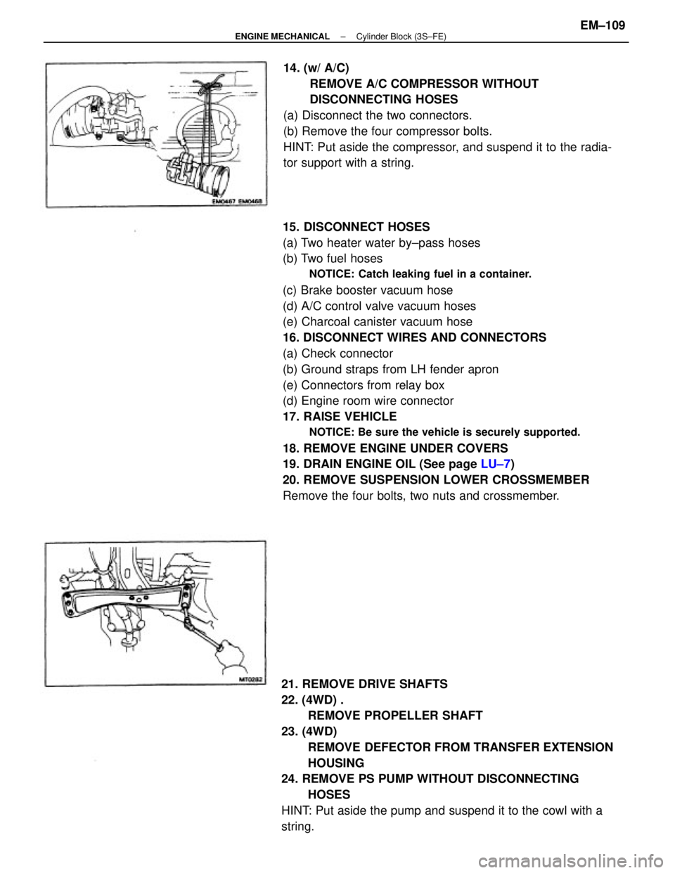
string.14. (w/ A/C)
REMOVE A/C COMPRESSOR WITHOUT
DISCONNECTING HOSES
(a) Disconnect the two connectors.
(b) Remove the four compressor bolts.
HINT: Put aside the compressor, and suspend it to the radia-
tor support with a string.
± ENGINE MECHANICALCylinder Block (3S±FE)EM±109
Page 1291 of 2389
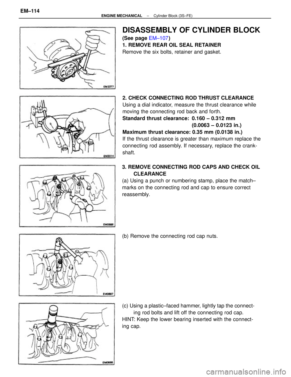
2. CHECK CONNECTING ROD THRUST CLEARANCE
Using a dial indicator, measure the thrust clearance while
moving the connecting rod back and forth.
Standard thrust clearance: 0.160 ± 0.312 mm
(0.0063 ± 0.0123 in.)
Maximum thrust clearance: 0.35 mm (0.0138 in.)
If the thrust clearance is greater than maximum replace the
connecting rod assembly. If necessary, replace the crank-
shaft.
3. REMOVE CONNECTING ROD CAPS AND CHECK OIL
CLEARANCE
(a) Using a punch or numbering stamp, place the match±
marks on the connecting rod and cap to ensure correct
reassembly.
(c) Using a plastic±faced hammer, lightly tap the connect-
ing rod bolts and lift off the connecting rod cap.
HINT: Keep the lower bearing inserted with the connect-
ing cap.
DISASSEMBLY OF CYLINDER BLOCK
(See page EM±107)
1. REMOVE REAR OIL SEAL RETAINER
Remove the six bolts, retainer and gasket.
(b) Remove the connecting rod cap nuts.
± ENGINE MECHANICALCylinder Block (3S±FE)EM±114
Page 1292 of 2389
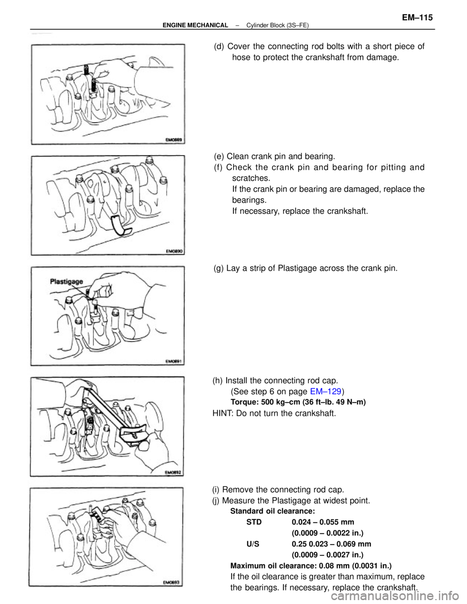
(i) Remove the connecting rod cap.
(j) Measure the Plastigage at widest point.
Standard oil clearance:
STD 0.024 ± 0.055 mm
(0.0009 ± 0.0022 in.)
U/S 0.25 0.023 ± 0.069 mm
(0.0009 ± 0.0027 in.)
Maximum oil clearance: 0.08 mm (0.0031 in.)
If the oil clearance is greater than maximum, replace
the bearings. If necessary, replace the crankshaft. (e) Clean crank pin and bearing.
(f) Check the crank pin and bearing for pitting and
scratches.
If the crank pin or bearing are damaged, replace the
bearings.
If necessary, replace the crankshaft.
(h) Install the connecting rod cap.
(See step 6 on page EM±129)
Torque: 500 kg±cm (36 ft±lb. 49 N±m)
HINT: Do not turn the crankshaft.(d) Cover the connecting rod bolts with a short piece of
hose to protect the crankshaft from damage.
(g) Lay a strip of Plastigage across the crank pin.
± ENGINE MECHANICALCylinder Block (3S±FE)EM±115
Page 1293 of 2389
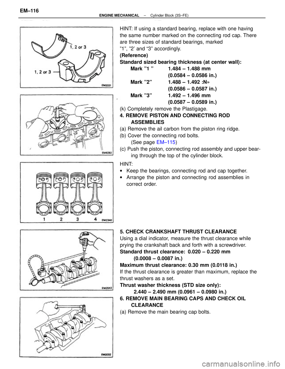
HINT: If using a standard bearing, replace with one having
the same number marked on the connecting rod cap. There
are three sizes of standard bearings, marked
º1º, º2' and ª3º accordingly.
(Reference)
Standard sized bearing thickness (at center wall):
Mark º1 º 1.484 ± 1.488 mm
(0.0584 ± 0.0586 in.)
Mark º2º 1.488 ± 1.492 :N»
(0.0586 ± 0.0587 in.)
Mark º3º 1.492 ± 1.496 mm
(0.0587 ± 0.0589 in.)
(k) Completely remove the Plastigage.
4. REMOVE PISTON AND CONNECTING ROD
ASSEMBLIES
(a) Remove the ail carbon from the piston ring ridge.
(b) Cover the connecting rod bolts.
(See page EM±115)
(c) Push the piston, connecting rod assembly and upper bear-
ing through the top of the cylinder block.
5. CHECK CRANKSHAFT THRUST CLEARANCE
Using a dial indicator, measure the thrust clearance while
prying the crankshaft back and forth with a screwdriver.
Standard thrust clearance: 0.020 ± 0.220 mm
(0.0008 ± 0.0087 in.)
Maximum thrust clearance: 0.30 mm (0.0118 in.)
If the thrust clearance is greater than maximum, replace the
thrust washers as a set.
Thrust washer thickness (STD size only):
2.440 ± 2.490 mm (0.0961 ± 0.0980 in.)
6. REMOVE MAIN BEARING CAPS AND CHECK OIL
CLEARANCE
(a) Remove the main bearing cap bolts. HINT:
wKeep the bearings, connecting rod and cap together.
wArrange the piston and connecting rod assemblies in
correct order.
± ENGINE MECHANICALCylinder Block (3S±FE)EM±116
Page 1294 of 2389
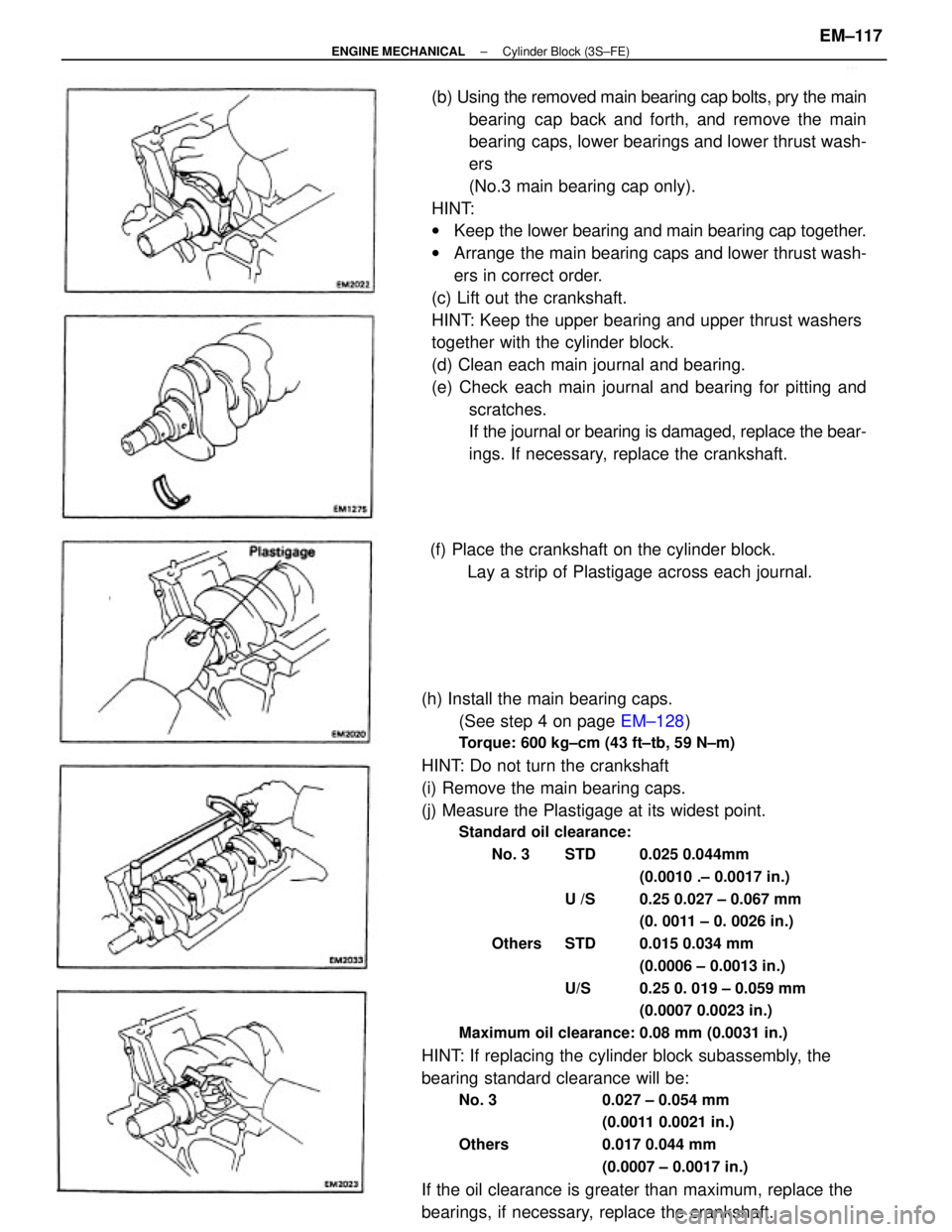
(h) Install the main bearing caps.
(See step 4 on page EM±128)
Torque: 600 kg±cm (43 ft±tb, 59 N±m)
HINT: Do not turn the crankshaft
(i) Remove the main bearing caps.
(j) Measure the Plastigage at its widest point.
Standard oil clearance:
No. 3 STD 0.025 0.044mm
(0.0010 .± 0.0017 in.)
U /S 0.25 0.027 ± 0.067 mm
(0. 0011 ± 0. 0026 in.)
Others STD 0.015 0.034 mm
(0.0006 ± 0.0013 in.)
U/S 0.25 0. 019 ± 0.059 mm
(0.0007 0.0023 in.)
Maximum oil clearance: 0.08 mm (0.0031 in.)
HINT: If replacing the cylinder block subassembly, the
bearing standard clearance will be:
No. 3 0.027 ± 0.054 mm
(0.0011 0.0021 in.)
Others 0.017 0.044 mm
(0.0007 ± 0.0017 in.)
If the oil clearance is greater than maximum, replace the
bearings, if necessary, replace the crankshaft.(b) Using the removed main bearing cap bolts, pry the main
bearing cap back and forth, and remove the main
bearing caps, lower bearings and lower thrust wash-
ers
(No.3 main bearing cap only).
HINT:
wKeep the lower bearing and main bearing cap together.
wArrange the main bearing caps and lower thrust wash-
ers in correct order.
(c) Lift out the crankshaft.
HINT: Keep the upper bearing and upper thrust washers
together with the cylinder block.
(d) Clean each main journal and bearing.
(e) Check each main journal and bearing for pitting and
scratches.
If the journal or bearing is damaged, replace the bear-
ings. If necessary, replace the crankshaft.
(f) Place the crankshaft on the cylinder block.
Lay a strip of Plastigage across each journal.
± ENGINE MECHANICALCylinder Block (3S±FE)EM±117
Page 1296 of 2389
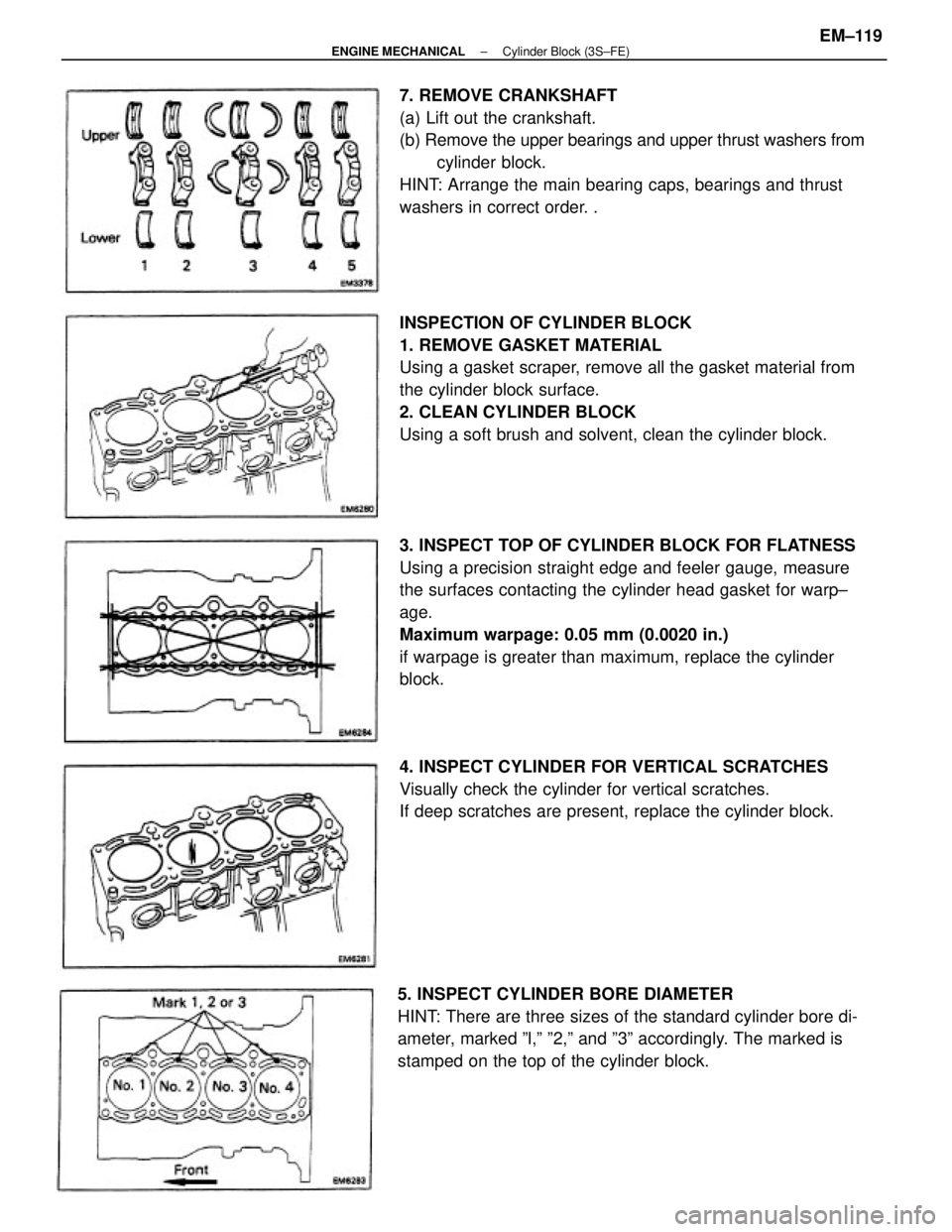
INSPECTION OF CYLINDER BLOCK
1. REMOVE GASKET MATERIAL
Using a gasket scraper, remove all the gasket material from
the cylinder block surface.
2. CLEAN CYLINDER BLOCK
Using a soft brush and solvent, clean the cylinder block.
3. INSPECT TOP OF CYLINDER BLOCK FOR FLATNESS
Using a precision straight edge and feeler gauge, measure
the surfaces contacting the cylinder head gasket for warp±
age.
Maximum warpage: 0.05 mm (0.0020 in.)
if warpage is greater than maximum, replace the cylinder
block. 7. REMOVE CRANKSHAFT
(a) Lift out the crankshaft.
(b) Remove the upper bearings and upper thrust washers from
cylinder block.
HINT: Arrange the main bearing caps, bearings and thrust
washers in correct order. .
5. INSPECT CYLINDER BORE DIAMETER
HINT: There are three sizes of the standard cylinder bore di-
ameter, marked ºl,º º2,º and º3º accordingly. The marked is
stamped on the top of the cylinder block.4. INSPECT CYLINDER FOR VERTICAL SCRATCHES
Visually check the cylinder for vertical scratches.
If deep scratches are present, replace the cylinder block.
± ENGINE MECHANICALCylinder Block (3S±FE)EM±119
Page 1297 of 2389
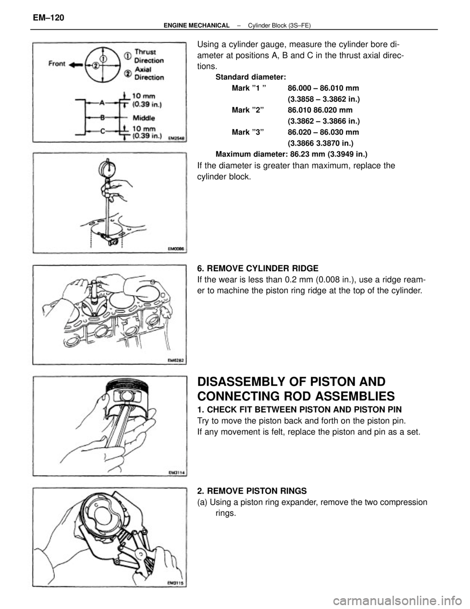
Using a cylinder gauge, measure the cylinder bore di-
ameter at positions A, B and C in the thrust axial direc-
tions.
Standard diameter:
Mark º1 º 86.000 ± 86.010 mm
(3.3858 ± 3.3862 in.)
Mark º2º 86.010 86.020 mm
(3.3862 ± 3.3866 in.)
Mark º3º 86.020 ± 86.030 mm
(3.3866 3.3870 in.)
Maximum diameter: 86.23 mm (3.3949 in.)
If the diameter is greater than maximum, replace the
cylinder block.
DISASSEMBLY OF PISTON AND
CONNECTING ROD ASSEMBLIES
1. CHECK FIT BETWEEN PISTON AND PISTON PIN
Try to move the piston back and forth on the piston pin.
If any movement is felt, replace the piston and pin as a set. 6. REMOVE CYLINDER RIDGE
If the wear is less than 0.2 mm (0.008 in.), use a ridge ream-
er to machine the piston ring ridge at the top of the cylinder.
2. REMOVE PISTON RINGS
(a) Using a piston ring expander, remove the two compression
rings.
± ENGINE MECHANICALCylinder Block (3S±FE)EM±120