check engine TOYOTA CAMRY V20 1986 Service Information
[x] Cancel search | Manufacturer: TOYOTA, Model Year: 1986, Model line: CAMRY V20, Model: TOYOTA CAMRY V20 1986Pages: 2389, PDF Size: 84.44 MB
Page 1238 of 2389
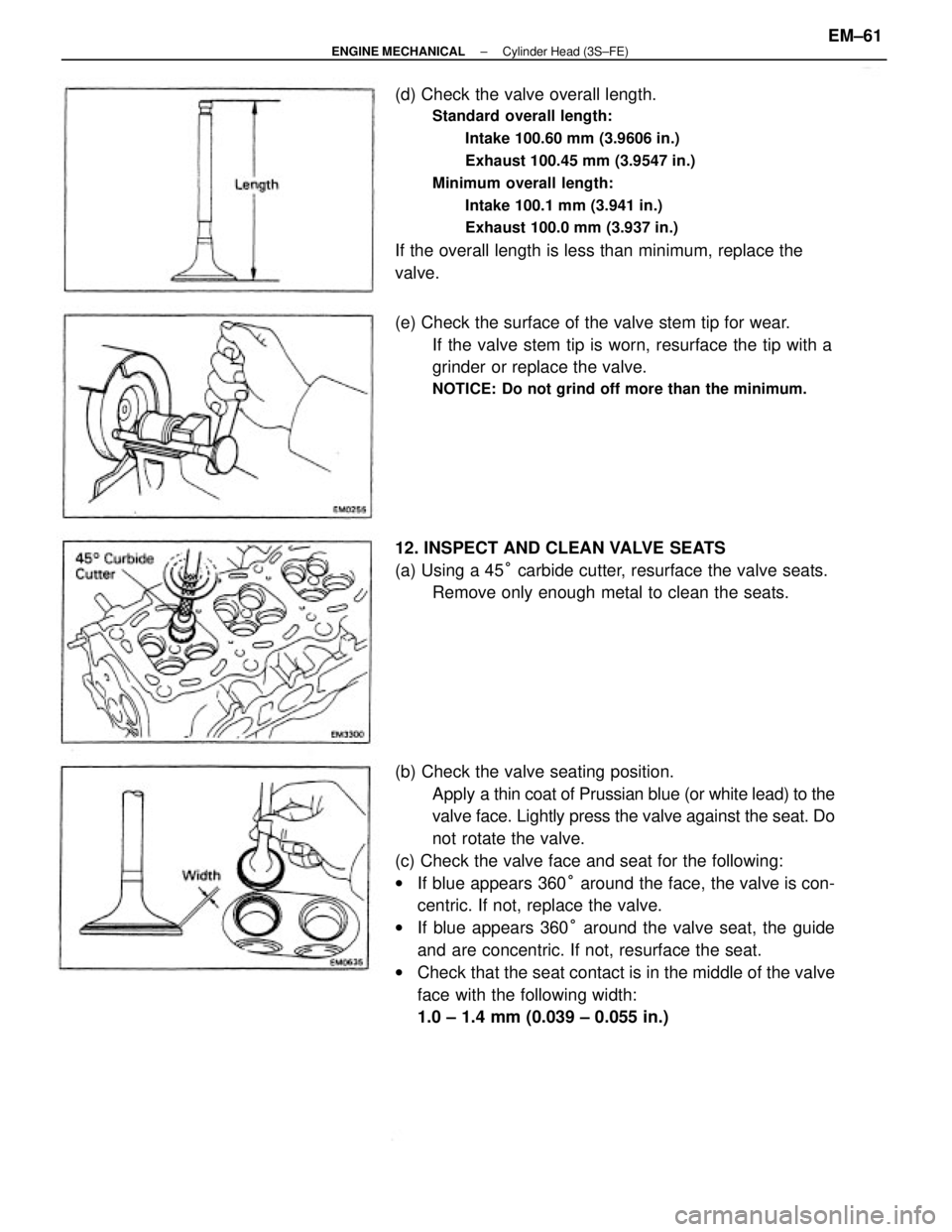
(b) Check the valve seating position.
Apply a thin coat of Prussian blue (or white lead) to the
valve face. Lightly press the valve against the seat. Do
not rotate the valve.
(c) Check the valve face and seat for the following:
wIf blue appears 360° around the face, the valve is con-
centric. If not, replace the valve.
wIf blue appears 360° around the valve seat, the guide
and are concentric. If not, resurface the seat.
wCheck that the seat contact is in the middle of the valve
face with the following width:
1.0 ± 1.4 mm (0.039 ± 0.055 in.) (d) Check the valve overall length.
Standard overall length:
Intake 100.60 mm (3.9606 in.)
Exhaust 100.45 mm (3.9547 in.)
Minimum overall length:
Intake 100.1 mm (3.941 in.)
Exhaust 100.0 mm (3.937 in.)
If the overall length is less than minimum, replace the
valve.
(e) Check the surface of the valve stem tip for wear.
If the valve stem tip is worn, resurface the tip with a
grinder or replace the valve.
NOTICE: Do not grind off more than the minimum.
12. INSPECT AND CLEAN VALVE SEATS
(a) Using a 45° carbide cutter, resurface the valve seats.
Remove only enough metal to clean the seats.
± ENGINE MECHANICALCylinder Head (3S±FE)EM±61
Page 1240 of 2389
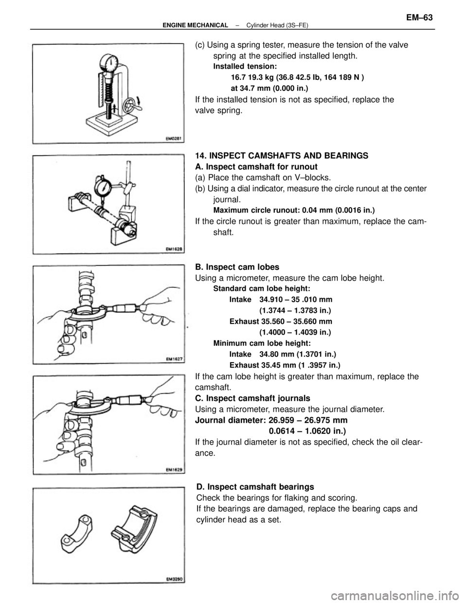
B. Inspect cam lobes
Using a micrometer, measure the cam lobe height.
Standard cam lobe height:
Intake 34.910 ± 35 .010 mm
(1.3744 ± 1.3783 in.)
Exhaust 35.560 ± 35.660 mm
(1.4000 ± 1.4039 in.)
Minimum cam lobe height:
Intake 34.80 mm (1.3701 in.)
Exhaust 35.45 mm (1 .3957 in.)
If the cam lobe height is greater than maximum, replace the
camshaft.
C. Inspect camshaft journals
Using a micrometer, measure the journal diameter.
Journal diameter: 26.959 ± 26.975 mm
0.0614 ± 1.0620 in.)
If the journal diameter is not as specified, check the oil clear-
ance. 14. INSPECT CAMSHAFTS AND BEARINGS
A. Inspect camshaft for runout
(a) Place the camshaft on V±blocks.
(b) Using a dial indicator, measure the circle runout at the center
journal.
Maximum circle runout: 0.04 mm (0.0016 in.)
If the circle runout is greater than maximum, replace the cam-
shaft. (c) Using a spring tester, measure the tension of the valve
spring at the specified installed length.
Installed tension:
16.7 19.3 kg (36.8 42.5 Ib, 164 189 N )
at 34.7 mm (0.000 in.)
If the installed tension is not as specified, replace the
valve spring.
D. Inspect camshaft bearings
Check the bearings for flaking and scoring.
If the bearings are damaged, replace the bearing caps and
cylinder head as a set.
± ENGINE MECHANICALCylinder Head (3S±FE)EM±63
Page 1243 of 2389
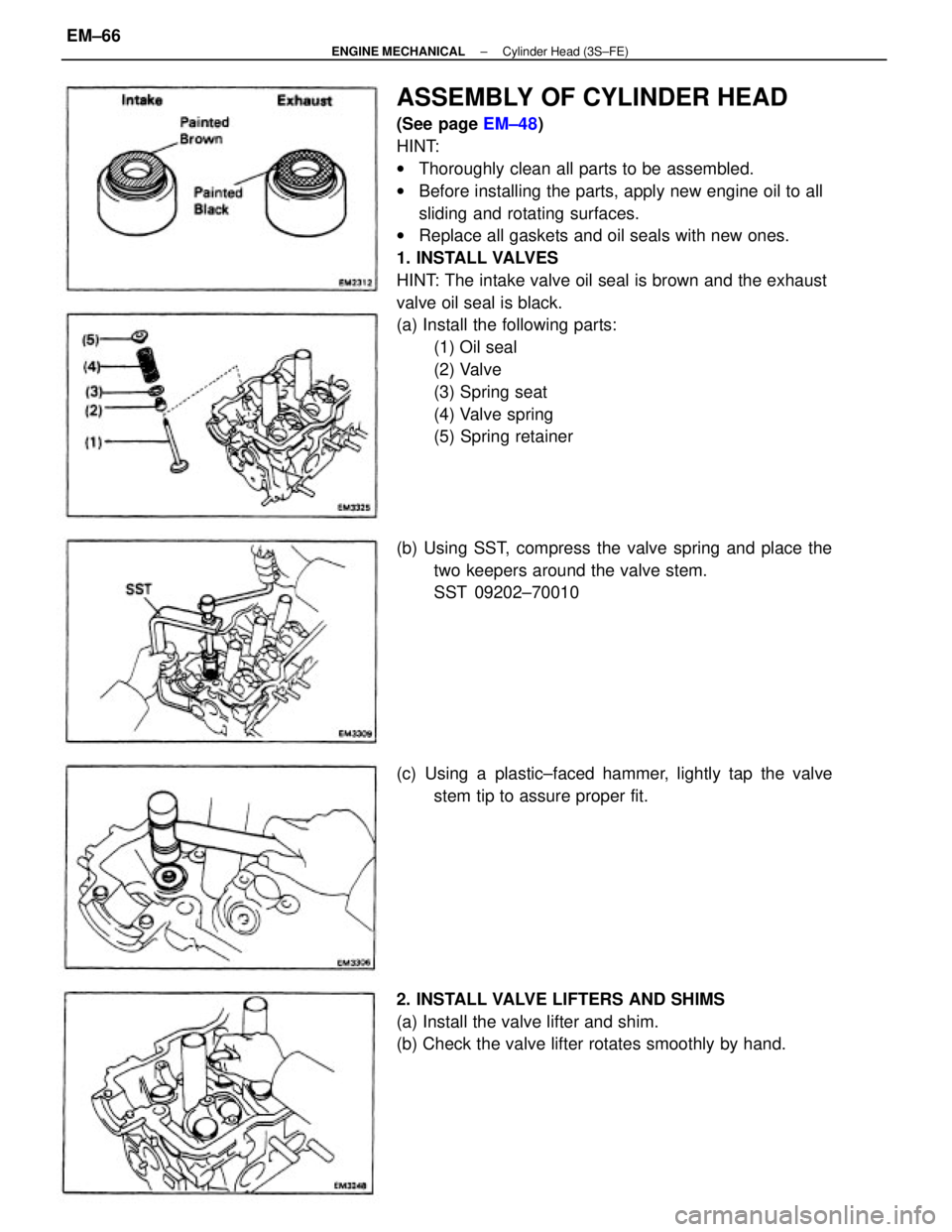
ASSEMBLY OF CYLINDER HEAD
(See page EM±48)
HINT:
wThoroughly clean all parts to be assembled.
wBefore installing the parts, apply new engine oil to all
sliding and rotating surfaces.
wReplace all gaskets and oil seals with new ones.
1. INSTALL VALVES
HINT: The intake valve oil seal is brown and the exhaust
valve oil seal is black.
(a) Install the following parts:
(1) Oil seal
(2) Valve
(3) Spring seat
(4) Valve spring
(5) Spring retainer
2. INSTALL VALVE LIFTERS AND SHIMS
(a) Install the valve lifter and shim.
(b) Check the valve lifter rotates smoothly by hand. (b) Using SST, compress the valve spring and place the
two keepers around the valve stem.
SST 09202±70010
(c) Using a plastic±faced hammer, lightly tap the valve
stem tip to assure proper fit.
± ENGINE MECHANICALCylinder Head (3S±FE)EM±66
Page 1244 of 2389
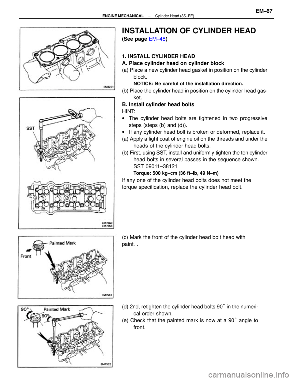
1. INSTALL CYLINDER HEAD
A. Place cylinder head on cylinder block
(a) Place a new cylinder head gasket in position on the cylinder
block.
NOTICE: Be careful of the installation direction.
(b) Place the cylinder head in position on the cylinder head gas-
ket.
B. Install cylinder head bolts
HINT:
wThe cylinder head bolts are tightened in two progressive
steps (steps (b) and (d)).
wIf any cylinder head bolt is broken or deformed, replace it.
(a) Apply a light coat of engine oil on the threads and under the
heads of the cylinder head bolts.
(b) First, using SST, install and uniformly tighten the ten cylinder
head bolts in several passes in the sequence shown.
SST 09011±38121
Torque: 500 kg±cm (36 ft±Ib, 49 N±m)
If any one of the cylinder head bolts does not meet the
torque specification, replace the cylinder head bolt.
(d) 2nd, retighten the cylinder head bolts 90° in the numeri-
cal order shown.
(e) Check that the painted mark is now at a 90° angle to
front.
INSTALLATION OF CYLINDER HEAD
(See page EM±48)
(c) Mark the front of the cylinder head bolt head with
paint. .
± ENGINE MECHANICALCylinder Head (3S±FE)EM±67
Page 1251 of 2389
26. INSTALL OIL PRESSURE SWITCH, ENGINE HANGERS
AND ALTERNATOR BRACKET
Torque the bolts.
Torque: 500 kg±cm (37 ft±Ib, 48 N±m)
27. INSTALL ALTERNATOR (See page CH±14)
28. INSTALL AIR CLEANER HOSE
29. INSTALL CRUISE CONTROL ACTUATOR
(See step 26 on page EM±137)
30. INSTALL RADIATOR RESERVOIR TANK
31. INSTALL ACCELERATOR CABLE, AND ADJUST IT
32. (A/T)
CONNECT THROTTLE CABLE, AND ADJUST IT
33. FILL WITH ENGINE COOLANT (See page CO±5)
Capacity (w/ Heater):
M/T 6.4 liters (6.8 US qts, 5.6 Imp. qts)
A/T (2WD) 6.3 liters (6.7 US qts, 5.5 Imp. qts)
A/T (4WD) 6.8 liters (7.2 US qts, 6.0 Imp. qts)
34. CONNECT CABLE TO NEGATIVE TERMINAL OF
BATTERY
35. START ENGINE AND CHECK FOR LEAKS
36. PERFORM ENGINE ADJUSTMENT
(a) Adjust the valve clearance. (See page EM±11)
Valve clearance (Cold):
Intake 0.19 ± 0.29 mm (0.007 ± 0.011 in.)
Exhaust 0.28 ± 0.38 mm (0.011 ± 0.015 in.)
(b) Adjust the ignition timing.
(See steps 7 to 10 on pages IG±16 and 17)
Ignition timing:
10° BTDC @ idle
(w/ Terminals TE 1 and E 1 connected)
37. CHECK TOE±IN (See page FA±5)
38. PERFORM ROAD TEST
Check for abnormal noise, shock, slippage, correct shift
points and smooth operation.
39. RECHECK ENGINE COOLANT LEVEL AND OIL LEVEL
± ENGINE MECHANICALCylinder Head (3S±FE)EM±74
Page 1263 of 2389
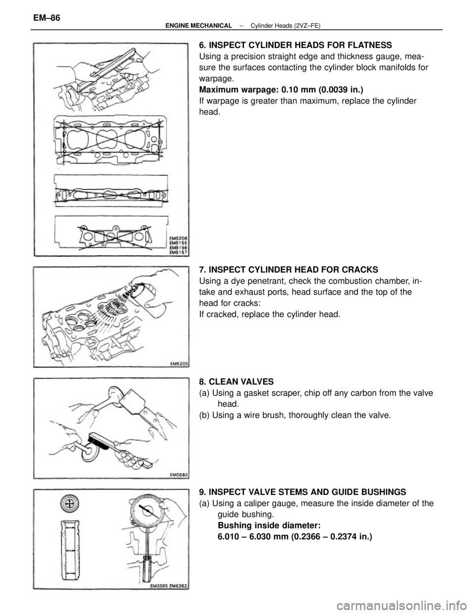
6. INSPECT CYLINDER HEADS FOR FLATNESS
Using a precision straight edge and thickness gauge, mea-
sure the surfaces contacting the cylinder block manifolds for
warpage.
Maximum warpage: 0.10 mm (0.0039 in.)
If warpage is greater than maximum, replace the cylinder
head.
7. INSPECT CYLINDER HEAD FOR CRACKS
Using a dye penetrant, check the combustion chamber, in-
take and exhaust ports, head surface and the top of the
head for cracks:
If cracked, replace the cylinder head.
9. INSPECT VALVE STEMS AND GUIDE BUSHINGS
(a) Using a caliper gauge, measure the inside diameter of the
guide bushing.
Bushing inside diameter:
6.010 ± 6.030 mm (0.2366 ± 0.2374 in.) 8. CLEAN VALVES
(a) Using a gasket scraper, chip off any carbon from the valve
head.
(b) Using a wire brush, thoroughly clean the valve.
± ENGINE MECHANICALCylinder Heads (2VZ±FE)EM±86
Page 1265 of 2389
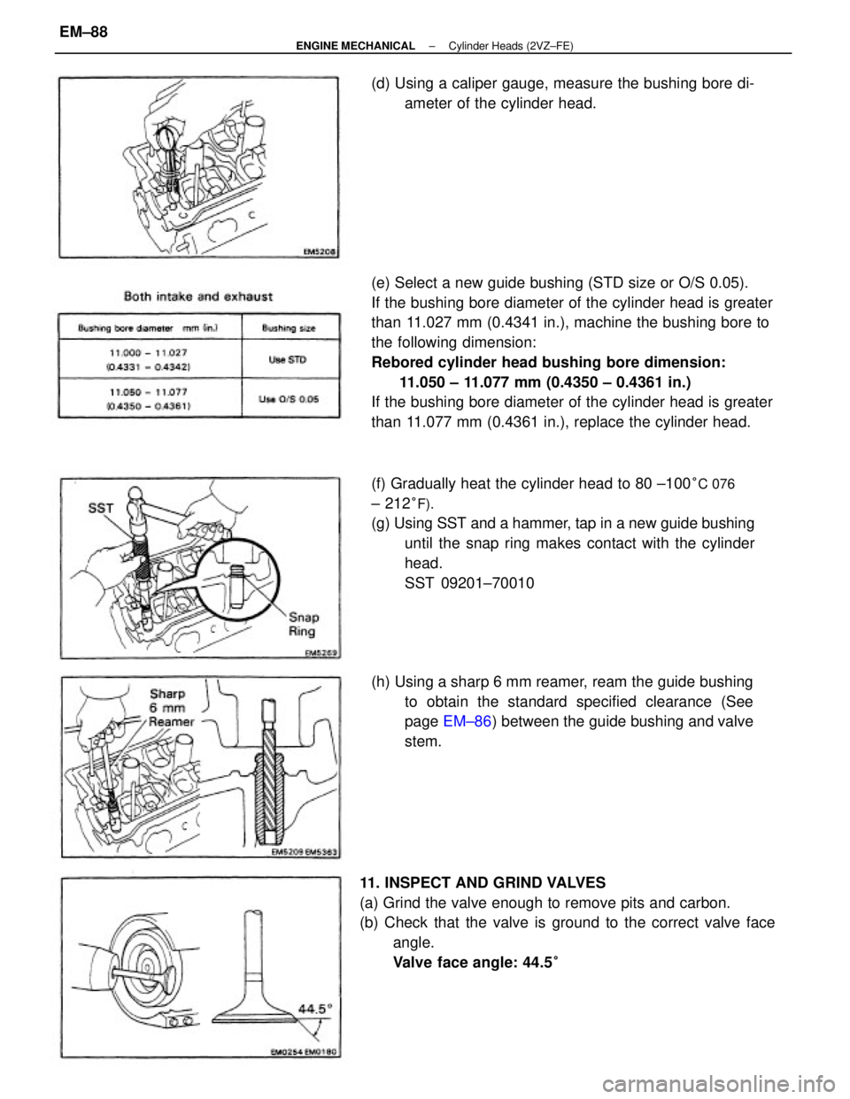
(e) Select a new guide bushing (STD size or O/S 0.05).
If the bushing bore diameter of the cylinder head is greater
than 11.027 mm (0.4341 in.), machine the bushing bore to
the following dimension:
Rebored cylinder head bushing bore dimension:
11.050 ± 11.077 mm (0.4350 ± 0.4361 in.)
If the bushing bore diameter of the cylinder head is greater
than 11.077 mm (0.4361 in.), replace the cylinder head.
11. INSPECT AND GRIND VALVES
(a) Grind the valve enough to remove pits and carbon.
(b) Check that the valve is ground to the correct valve face
angle.
Valve face angle: 44.5
°
(f) Gradually heat the cylinder head to 80 ±100°C 076
± 212°F).
(g) Using SST and a hammer, tap in a new guide bushing
until the snap ring makes contact with the cylinder
head.
SST 09201±70010
(h) Using a sharp 6 mm reamer, ream the guide bushing
to obtain the standard specified clearance (See
page EM±86) between the guide bushing and valve
stem. (d) Using a caliper gauge, measure the bushing bore di-
ameter of the cylinder head.
± ENGINE MECHANICALCylinder Heads (2VZ±FE)EM±88
Page 1266 of 2389

(b) Check the valve seating position.
Apply a thin coat of Prussian blue (or white lead) to the
valve face. Lightly press the valve against the seat. Do
not rotate the valve.
(c) Check the valve face and seat for the following:
wIf blue appears 360° around the face, the valve is con-
centric. If not, replace the valve.
wIf blue appears 360° around the valve seat, the guide
and face are concentric. If not, resurface the seat.
wCheck that the seat contact is in the middle of the valve
face with the following width:
1.0 ± 1.4 mm (0.039 ± 0.055 in.) (d) Check the valve overall length.
Standard overall length:
Intake 96.1 mm (3.783 in.)
Exhaust 96.2 mm (3.787 in.)
Minimum overall length:
Intake 95.6 mm (3.754 in.)
Exhaust 95.7 mm (3.768 in.)
If the overall length is less than minimum, replace the
valve. (c) Check the valve head margin thickness.
Standard margin thickness: 1.0 mm (0.039 in.)
Minimum margin thickness: 0.5 mm (0.020 in.)
If the margin thickness is less than minimum, replace
the valve.
(e) Check the surface of the valve stem tip for wear.
If the valve stem tip is worn, resurface the tip with a
grinder or replace the valve.
NOTICE: Do not grind off more than the minimum.
12. INSPECT AND CLEAN VALVE SEATS
(a) Using a 455 carbide cutter, resurface the valve seats.
Remove only enough metal to clean the seats.
± ENGINE MECHANICALCylinder Heads (2VZ±FE)EM±89
Page 1268 of 2389
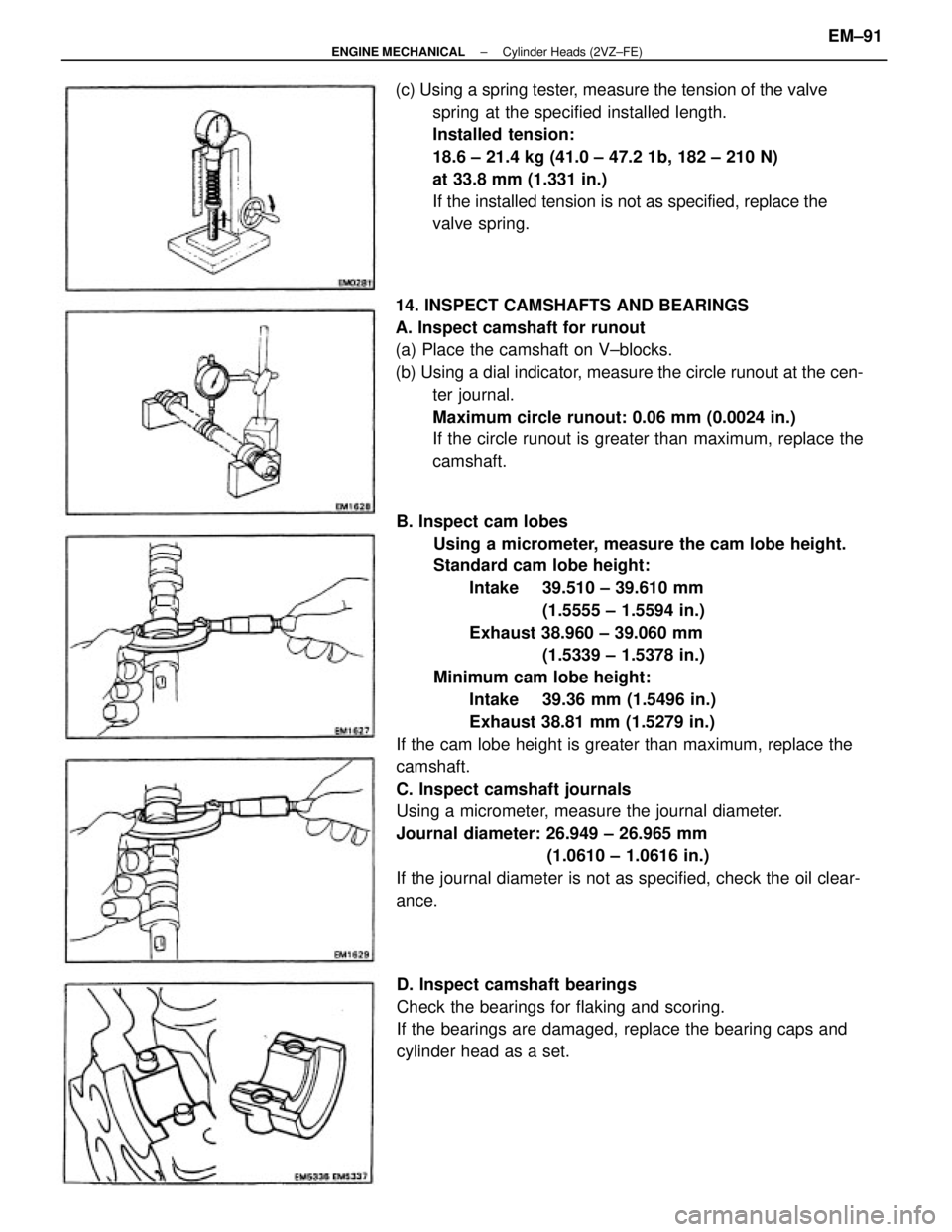
B. Inspect cam lobes
Using a micrometer, measure the cam lobe height.
Standard cam lobe height:
Intake 39.510 ± 39.610 mm
(1.5555 ± 1.5594 in.)
Exhaust 38.960 ± 39.060 mm
(1.5339 ± 1.5378 in.)
Minimum cam lobe height:
Intake 39.36 mm (1.5496 in.)
Exhaust 38.81 mm (1.5279 in.)
If the cam lobe height is greater than maximum, replace the
camshaft.
C. Inspect camshaft journals
Using a micrometer, measure the journal diameter.
Journal diameter: 26.949 ± 26.965 mm
(1.0610 ± 1.0616 in.)
If the journal diameter is not as specified, check the oil clear-
ance. 14. INSPECT CAMSHAFTS AND BEARINGS
A. Inspect camshaft for runout
(a) Place the camshaft on V±blocks.
(b) Using a dial indicator, measure the circle runout at the cen-
ter journal.
Maximum circle runout: 0.06 mm (0.0024 in.)
If the circle runout is greater than maximum, replace the
camshaft. (c) Using a spring tester, measure the tension of the valve
spring at the specified installed length.
Installed tension:
18.6 ± 21.4 kg (41.0 ± 47.2 1b, 182 ± 210 N)
at 33.8 mm (1.331 in.)
If the installed tension is not as specified, replace the
valve spring.
D. Inspect camshaft bearings
Check the bearings for flaking and scoring.
If the bearings are damaged, replace the bearing caps and
cylinder head as a set.
± ENGINE MECHANICALCylinder Heads (2VZ±FE)EM±91
Page 1272 of 2389
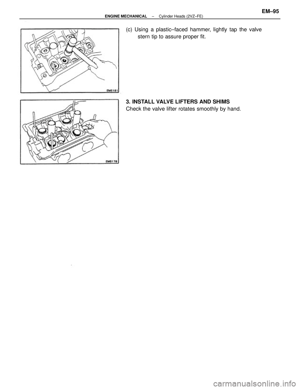
(c) Using a plastic±faced hammer, lightly tap the valve
stern tip to assure proper fit.
3. INSTALL VALVE LIFTERS AND SHIMS
Check the valve lifter rotates smoothly by hand.
± ENGINE MECHANICALCylinder Heads (2VZ±FE)EM±95