TOYOTA CAMRY V20 1986 Service Information
Manufacturer: TOYOTA, Model Year: 1986, Model line: CAMRY V20, Model: TOYOTA CAMRY V20 1986Pages: 2389, PDF Size: 84.44 MB
Page 1891 of 2389
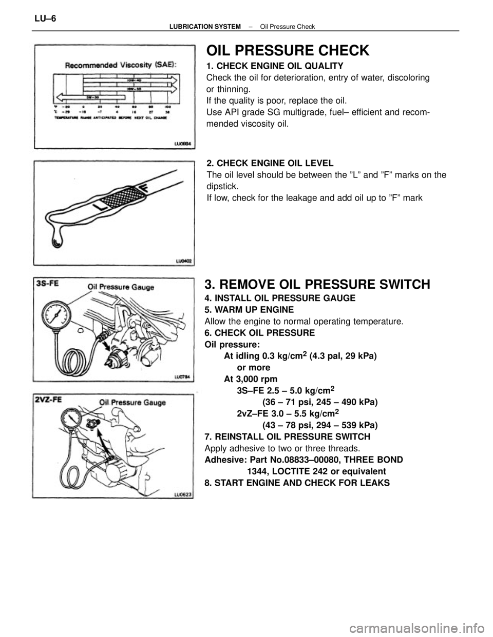
3. REMOVE OIL PRESSURE SWITCH
4. INSTALL OIL PRESSURE GAUGE
5. WARM UP ENGINE
Allow the engine to normal operating temperature.
6. CHECK OIL PRESSURE
Oil pressure:
At idling 0.3 kg/cm
2 (4.3 pal, 29 kPa)
or more
At 3,000 rpm
3S±FE 2.5 ± 5.0 kg/cm
2
(36 ± 71 psi, 245 ± 490 kPa)
2vZ±FE 3.0 ± 5.5 kg/cm
2
(43 ± 78 psi, 294 ± 539 kPa)
7. REINSTALL OIL PRESSURE SWITCH
Apply adhesive to two or three threads.
Adhesive: Part No.08833±00080, THREE BOND
1344, LOCTITE 242 or equivalent
8. START ENGINE AND CHECK FOR LEAKS
OIL PRESSURE CHECK
1. CHECK ENGINE OIL QUALITY
Check the oil for deterioration, entry of water, discoloring
or thinning.
If the quality is poor, replace the oil.
Use API grade SG multigrade, fuel± efficient and recom-
mended viscosity oil.
2. CHECK ENGINE OIL LEVEL
The oil level should be between the ºLº and ºFº marks on the
dipstick.
If low, check for the leakage and add oil up to ºFº mark
± LUBRICATION SYSTEMOil Pressure CheckLU±6
Page 1892 of 2389
REPLACEMENT OF ENGINE OIL
AND OIL FILTER
NOTICE:
wProlonged and repeated contact with mineral oil will re-
sult in the removal of natural¿¿ts from the skin, leading
to dryness, irritation and dermatitis. In addition, used en-
gine oil contains potentially harmful contaminants
which may cause skin cancer.
wCare should be taken, therefore, when changing engine
oil, to minimize the frequency and length of time your
skin is exposed to used engine oil. Protective clothing
and gloves, that cannot be penetrated by oil, should be
worn. The skin should be thoroughly washed with soap
and water, or use waterless hand cleaner, to remove any
used engine oil. Do not use gasoline, thinners, or sol-
vents.
wIn order to preserve the environment, used oil must be
disposed of only at designated disposal sites.
1. DRAIN ENGINE OIL
(a) Remove the oil filler cap.
(b) Remove the oil drain plug, and drain the oil into a container.
2. REPLACE OIL FILTER
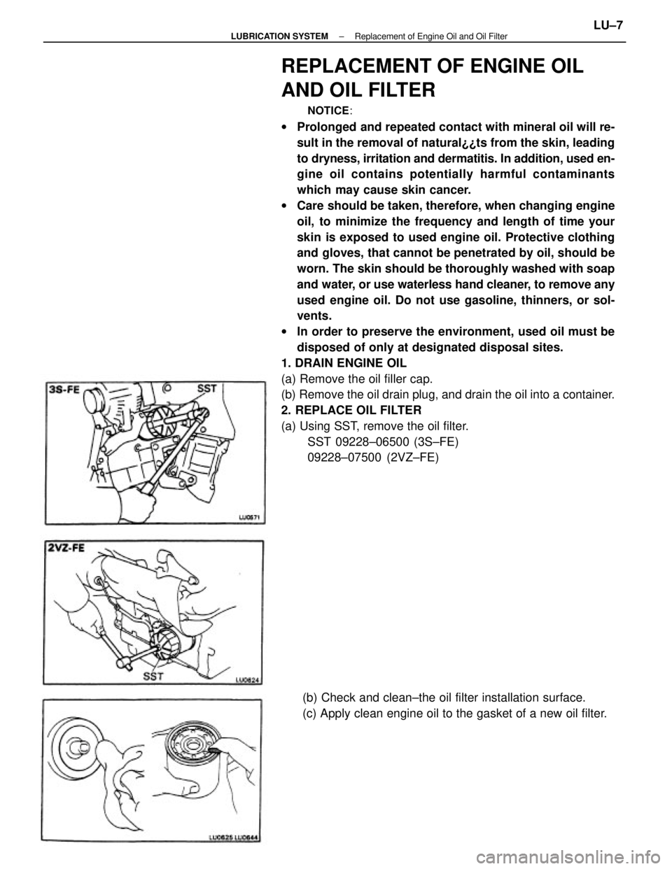
(a) Using SST, remove the oil filter.
SST 09228±06500 (3S±FE)
09228±07500 (2VZ±FE)
(b) Check and clean±the oil filter installation surface.
(c) Apply clean engine oil to the gasket of a new oil filter.
± LUBRICATION SYSTEMReplacement of Engine Oil and Oil FilterLU±7
Page 1893 of 2389
3. FILL WITH ENGINE OIL
(a) Clean and install the oil drain plug with a new gasket.
Torque: 2VZ±FE 3S±FE 400 kg±cm (29 ft±lb, 39 N±m)
(b) Fill with new engine oil (API grade SG muitigrade,
fuel±efficient and recommended viscosity oil).
Capacity (3S±FE):
Drain and refill
w/ Oil filter change
4.1 liters (4.3 U S qts, 3.6 Imp. qts)
w/o Oil filter change
3.7 liters (3.9 US qts, 3.3 Imp. qts)
Dry fill 4.5 liters (4.8 U S qts, 4.4 Imp. qts)
Capacity (2VZ±FE):
Drain and refill
w/ Oil filter change
3.9 liters (4.1 US qts, 3.4 Imp. qts)
w/o Oil filter change
3.7 liters (3.9 US qts, 3.3 Imp. qts)
Dry fill 4.6 liters (4.8 US qts, 4.4 Imp. qts)
(c) Install the oil filler cap.
4. START ENGINE AND CHECK FOR LEAKS
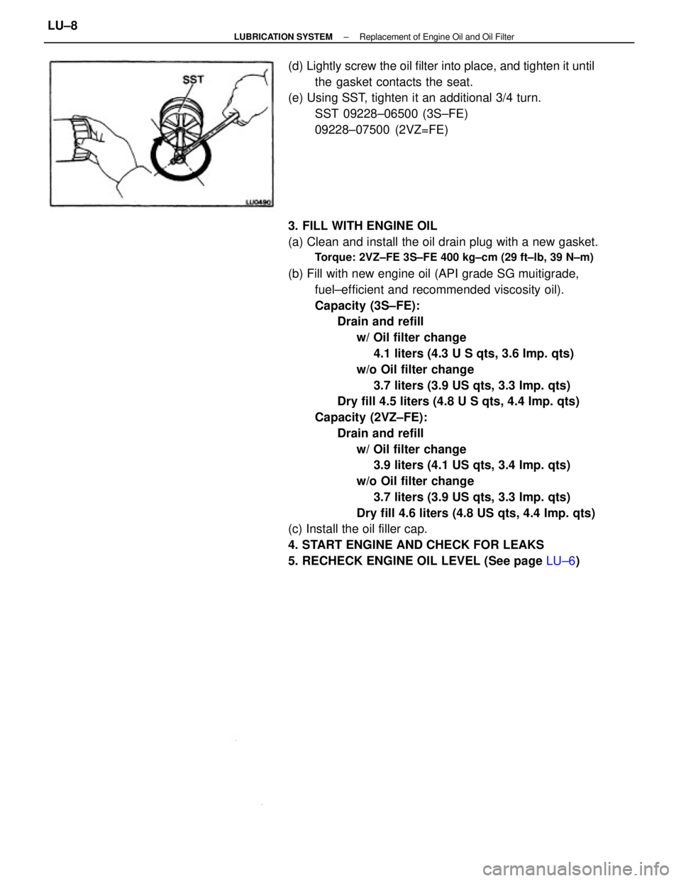
5. RECHECK ENGINE OIL LEVEL (See page LU±6) (d) Lightly screw the oil filter into place, and tighten it until
the gasket contacts the seat.
(e) Using SST, tighten it an additional 3/4 turn.
SST 09228±06500 (3S±FE)
09228±07500 (2VZ=FE)
± LUBRICATION SYSTEMReplacement of Engine Oil and Oil FilterLU±8
Page 1894 of 2389
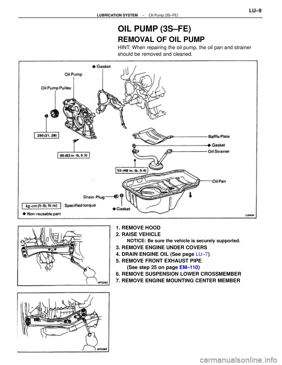
1. REMOVE HOOD
2. RAISE VEHICLE
NOTICE: Be sure the vehicle is securely supported.
3. REMOVE ENGINE UNDER COVERS
4. DRAIN ENGINE OIL (See page LU±7)
5. REMOVE FRONT EXHAUST PIPE
(See step 25 on page EM±110)
6. REMOVE SUSPENSION LOWER CROSSMEMBER
7. REMOVE ENGINE MOUNTING CENTER MEMBER
OIL PUMP (3S±FE)
REMOVAL OF OIL PUMP
HINT: When repairing the oil pump, the oil pan and strainer
should be removed and cleaned.
± LUBRICATION SYSTEMOil Pump (3S±FE)LU±9
Page 1895 of 2389
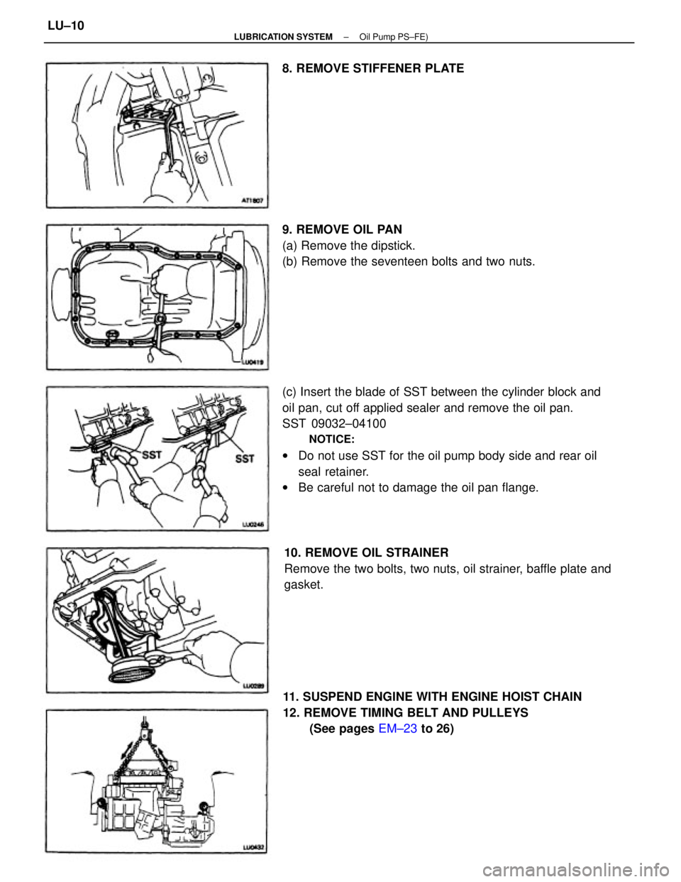
(c) Insert the blade of SST between the cylinder block and
oil pan, cut off applied sealer and remove the oil pan.
SST 09032±04100
NOTICE:
wDo not use SST for the oil pump body side and rear oil
seal retainer.
wBe careful not to damage the oil pan flange.
11. SUSPEND ENGINE WITH ENGINE HOIST CHAIN
12. REMOVE TIMING BELT AND PULLEYS
(See pages EM±23 to 26) 10. REMOVE OIL STRAINER
Remove the two bolts, two nuts, oil strainer, baffle plate and
gasket. 9. REMOVE OIL PAN
(a) Remove the dipstick.
(b) Remove the seventeen bolts and two nuts. 8. REMOVE STIFFENER PLATE
± LUBRICATION SYSTEMOil Pump PS±FE)LU±10
Page 1896 of 2389
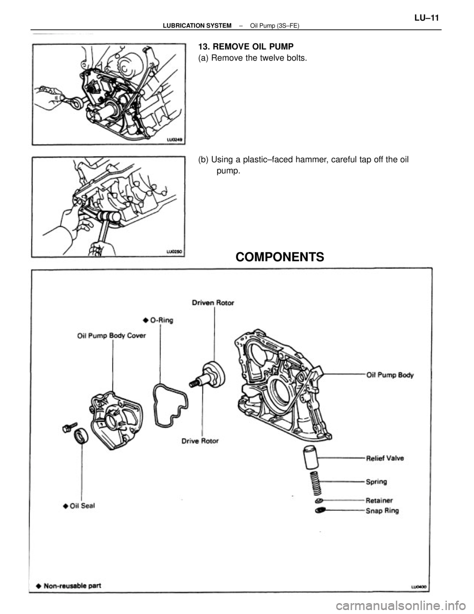
(b) Using a plastic±faced hammer, careful tap off the oil
pump. 13. REMOVE OIL PUMP
(a) Remove the twelve bolts.
COMPONENTS
± LUBRICATION SYSTEMOil Pump (3S±FE)LU±11
Page 1897 of 2389
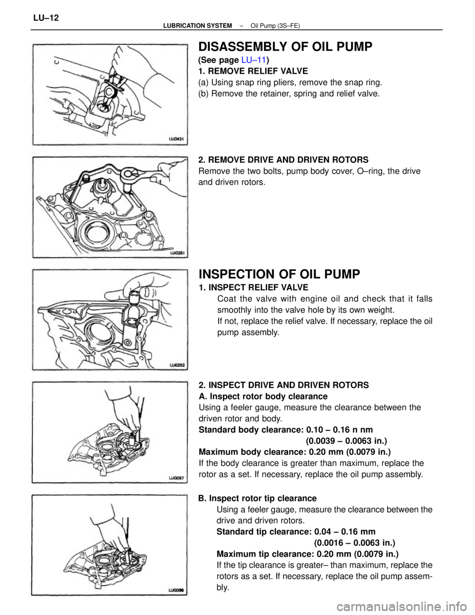
2. INSPECT DRIVE AND DRIVEN ROTORS
A. Inspect rotor body clearance
Using a feeler gauge, measure the clearance between the
driven rotor and body.
Standard body clearance: 0.10 ± 0.16 n nm
(0.0039 ± 0.0063 in.)
Maximum body clearance: 0.20 mm (0.0079 in.)
If the body clearance is greater than maximum, replace the
rotor as a set. If necessary, replace the oil pump assembly.
B. Inspect rotor tip clearance
Using a feeler gauge, measure the clearance between the
drive and driven rotors.
Standard tip clearance: 0.04 ± 0.16 mm
(0.0016 ± 0.0063 in.)
Maximum tip clearance: 0.20 mm (0.0079 in.)
If the tip clearance is greater± than maximum, replace the
rotors as a set. If necessary, replace the oil pump assem-
bly.
INSPECTION OF OIL PUMP
1. INSPECT RELIEF VALVE
Coat the valve with engine oil and check that it falls
smoothly into the valve hole by its own weight.
If not, replace the relief valve. If necessary, replace the oil
pump assembly.
DISASSEMBLY OF OIL PUMP
(See page LU±11)
1. REMOVE RELIEF VALVE
(a) Using snap ring pliers, remove the snap ring.
(b) Remove the retainer, spring and relief valve.
2. REMOVE DRIVE AND DRIVEN ROTORS
Remove the two bolts, pump body cover, O±ring, the drive
and driven rotors.
± LUBRICATION SYSTEMOil Pump (3S±FE)LU±12
Page 1898 of 2389
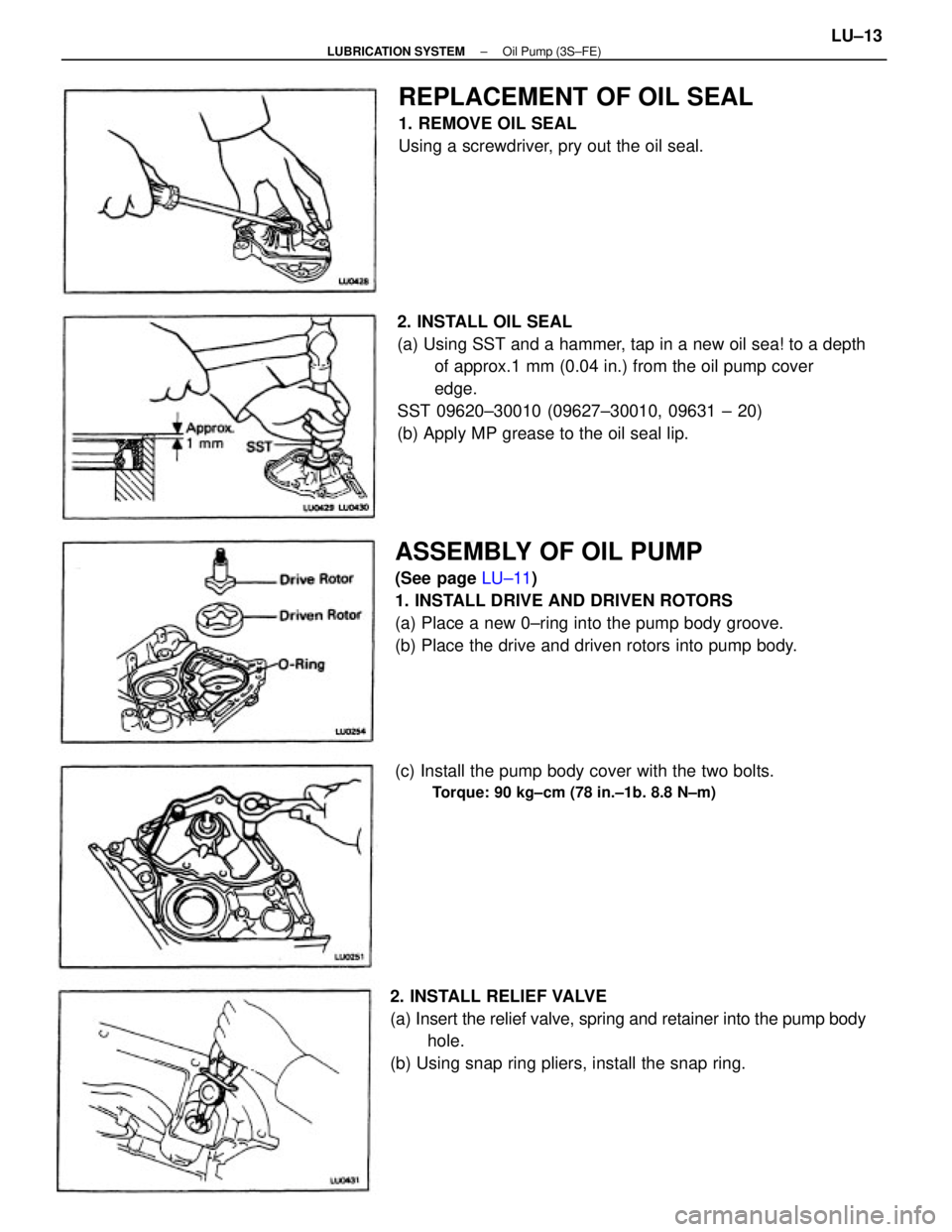
2. INSTALL OIL SEAL
(a) Using SST and a hammer, tap in a new oil sea! to a depth
of approx.1 mm (0.04 in.) from the oil pump cover
edge.
SST 09620±30010 (09627±30010, 09631 ± 20)
(b) Apply MP grease to the oil seal lip.
ASSEMBLY OF OIL PUMP
(See page LU±11)
1. INSTALL DRIVE AND DRIVEN ROTORS
(a) Place a new 0±ring into the pump body groove.
(b) Place the drive and driven rotors into pump body.
2. INSTALL RELIEF VALVE
(a) Insert the relief valve, spring and retainer into the pump body
hole.
(b) Using snap ring pliers, install the snap ring.
REPLACEMENT OF OIL SEAL
1. REMOVE OIL SEAL
Using a screwdriver, pry out the oil seal.
(c) Install the pump body cover with the two bolts.
Torque: 90 kg±cm (78 in.±1b. 8.8 N±m)
± LUBRICATION SYSTEMOil Pump (3S±FE)LU±13
Page 1899 of 2389
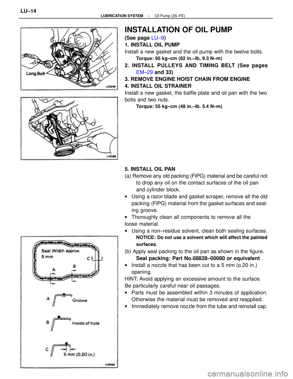
5. INSTALL OIL PAN
(a) Remove any old packing (FIPG) material and be careful not
to drop any oil on the contact surfaces of the oil pan
and cylinder block.
wUsing a razor blade and gasket scraper, remove all the old
packing (FlPG) material from the gasket surfaces and seal-
ing groove.
wThoroughly clean all components to remove all the
loose material.
wUsing a non±residue solvent, clean both sealing surfaces.
NOTICE: Do not use a solvent which will affect the painted
surfaces.
(b) Apply seal packing to the oil pan as shown in the figure.
Seal packing: Part No.08828±00080 or equivalent
wInstall a nozzle that has been cut to a 5 mm (o.20 in.)
opening.
HINT: Avoid applying an excessive amount to the surface.
Be particularly careful near oil passages.
wParts must be assembled within 3 minutes of application.
Otherwise the material must be removed and reapplied.
wImmediately remove nozzle from the tube and reinstall cap.
INSTALLATION OF OIL PUMP
(See page LU±9)
1. INSTALL OIL PUMP
Install a new gasket and the oil pump with the twelve bolts.
Torque: 95 kg±cm (82 in.±Ib, 9.3 N±m)
2. INSTALL PULLEYS AND TIMING BELT (See pages
EM±29 and 33)
3. REMOVE ENGINE HOIST CHAIN FROM ENGINE
4. INSTALL OIL STRAINER
Install a new gasket, the baffle plate and oil pan with the two
bolts and two nuts.
Torque: 55 kg±cm (48 in.±Ib. 5.4 N±m)
± LUBRICATION SYSTEMOil Pump (3S±FE)LU±14
Page 1900 of 2389
9. INSTALL FRONT EXHAUST PIPE
(See step 12 on page EM±134)
10. INSTALL ENGINE UNDER COVERS
11. LOWER VEHICLE
12. FILL WITH ENGINE OIL (See page LU±8)
13. START ENGINE AND CHECK FOR LEAKS
14. RECHECK ENGINE OIL LEVEL (See page LU±6)
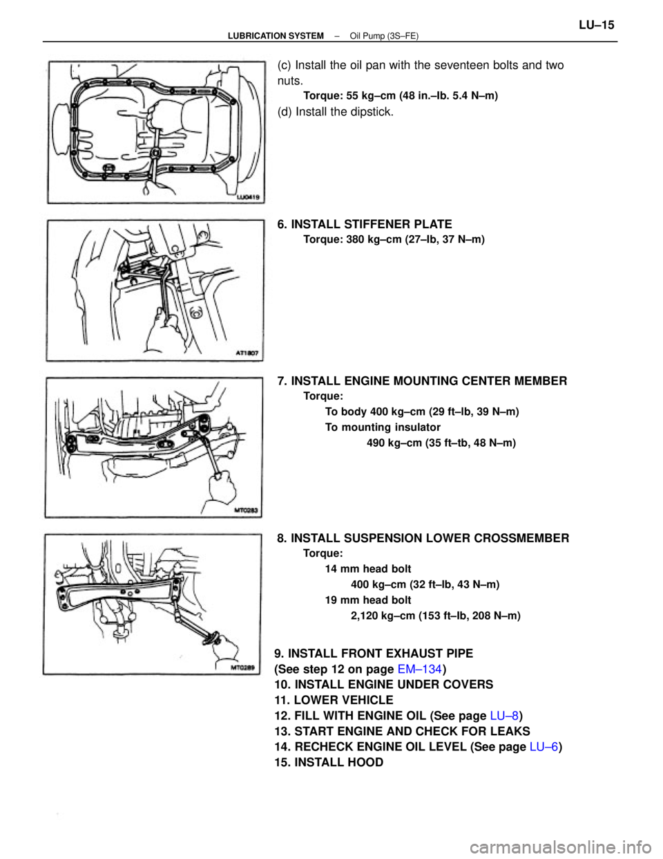
15. INSTALL HOOD8. INSTALL SUSPENSION LOWER CROSSMEMBER
Torque:
14 mm head bolt
400 kg±cm (32 ft±lb, 43 N±m)
19 mm head bolt
2,120 kg±cm (153 ft±Ib, 208 N±m)
7. INSTALL ENGINE MOUNTING CENTER MEMBER
Torque:
To body 400 kg±cm (29 ft±lb, 39 N±m)
To mounting insulator
490 kg±cm (35 ft±tb, 48 N±m)
(c) Install the oil pan with the seventeen bolts and two
nuts.
Torque: 55 kg±cm (48 in.±Ib. 5.4 N±m)
(d) Install the dipstick.
6. INSTALL STIFFENER PLATE
Torque: 380 kg±cm (27±Ib, 37 N±m)
± LUBRICATION SYSTEMOil Pump (3S±FE)LU±15