TOYOTA CAMRY V20 1986 Service Information
CAMRY V20 1986
TOYOTA
TOYOTA
https://www.carmanualsonline.info/img/14/57449/w960_57449-0.png
TOYOTA CAMRY V20 1986 Service Information
Trending: battery location, jump cable, door lock, fuel tank removal, instrument panel, check engine, engine overheat
Page 901 of 2389
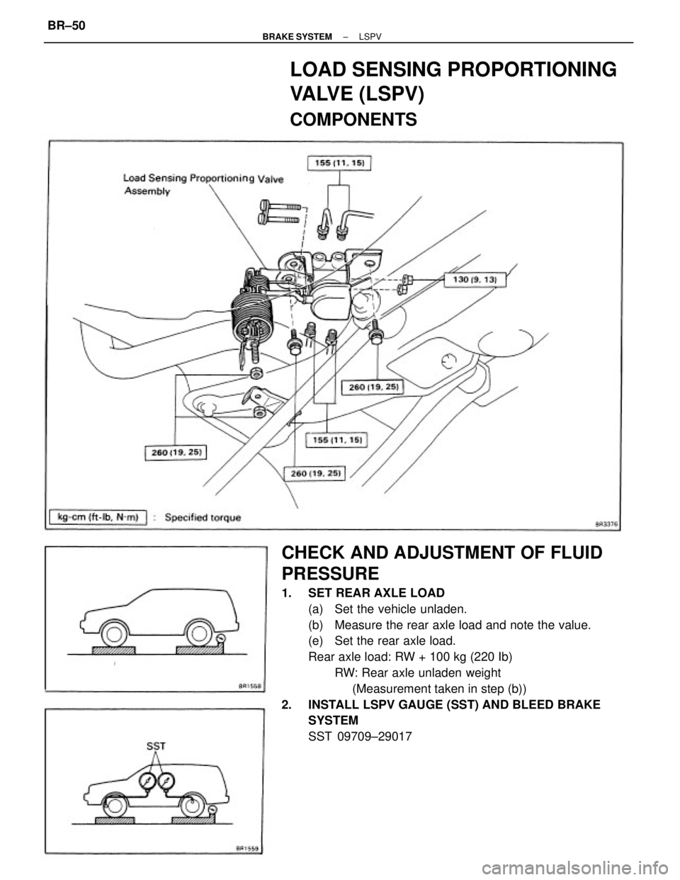
CHECK AND ADJUSTMENT OF FLUID
PRESSURE
1. SET REAR AXLE LOAD
(a) Set the vehicle unladen.
(b) Measure the rear axle load and note the value.
(e) Set the rear axle load.
Rear axle load: RW + 100 kg (220 Ib)
RW: Rear axle unladen weight
(Measurement taken in step (b))
2. INSTALL LSPV GAUGE (SST) AND BLEED BRAKE
SYSTEM
SST 09709±29017
LOAD SENSING PROPORTIONING
VALVE (LSPV)
COMPONENTS
± BRAKE SYSTEMLSPVBR±50
Page 902 of 2389
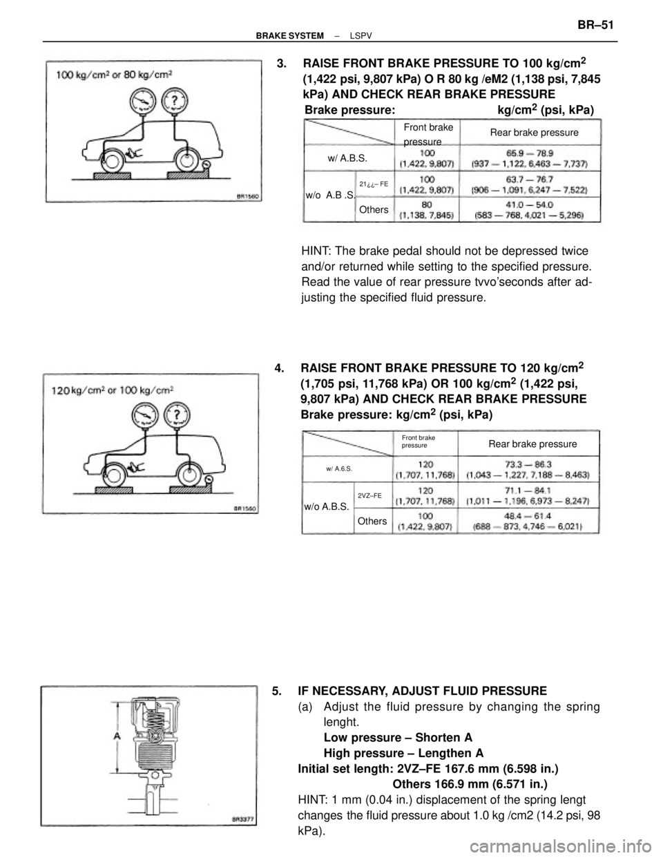
5. IF NECESSARY, ADJUST FLUID PRESSURE
(a) Adjust the fluid pressure by changing the spring
lenght.
Low pressure ± Shorten A
High pressure ± Lengthen A
Initial set length: 2VZ±FE 167.6 mm (6.598 in.)
Others 166.9 mm (6.571 in.)
HINT: 1 mm (0.04 in.) displacement of the spring lengt
changes the fluid pressure about 1.0 kg /cm2 (14.2 psi, 98
kPa). 4. RAISE FRONT BRAKE PRESSURE TO 120 kg/cm
2
(1,705 psi, 11,768 kPa) OR 100 kg/cm2 (1,422 psi,
9,807 kPa) AND CHECK REAR BRAKE PRESSURE
Brake pressure: kg/cm
2 (psi, kPa) 3. RAISE FRONT BRAKE PRESSURE TO 100 kg/cm
2
(1,422 psi, 9,807 kPa) O R 80 kg /eM2 (1,138 psi, 7,845
kPa) AND CHECK REAR BRAKE PRESSURE
Brake pressure: kg/cm
2 (psi, kPa)
HINT: The brake pedal should not be depressed twice
and/or returned while setting to the specified pressure.
Read the value of rear pressure tvvo'seconds after ad-
justing the specified fluid pressure.
Rear brake pressure
Rear brake pressure Front brake
pressure
Front brake
pressure
w/o A.B.S.w/o A.B .S.w/ A.B.S.
w/ A.6.S.
OthersOthers
2VZ±FE21¿¿± FE
± BRAKE SYSTEMLSPVBR±51
Page 903 of 2389
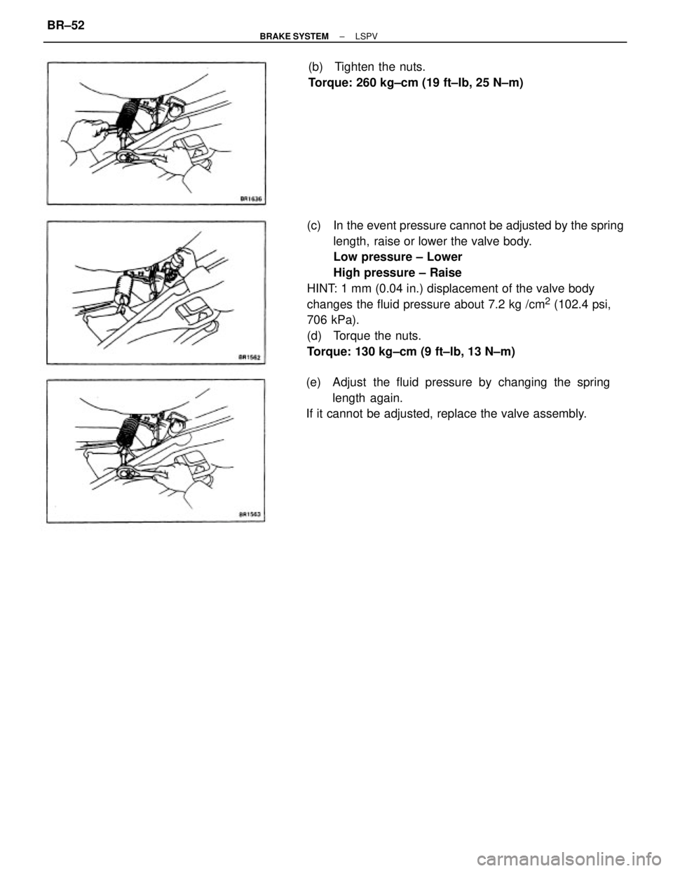
(c) In the event pressure cannot be adjusted by the spring
length, raise or lower the valve body.
Low pressure ± Lower
High pressure ± Raise
HINT: 1 mm (0.04 in.) displacement of the valve body
changes the fluid pressure about 7.2 kg /cm
2 (102.4 psi,
706 kPa).
(d) Torque the nuts.
Torque: 130 kg±cm (9 ft±lb, 13 N±m)
(e) Adjust the fluid pressure by changing the spring
length again.
If it cannot be adjusted, replace the valve assembly.(b) Tighten the nuts.
Torque: 260 kg±cm (19 ft±Ib, 25 N±m)
± BRAKE SYSTEMLSPVBR±52
Page 904 of 2389
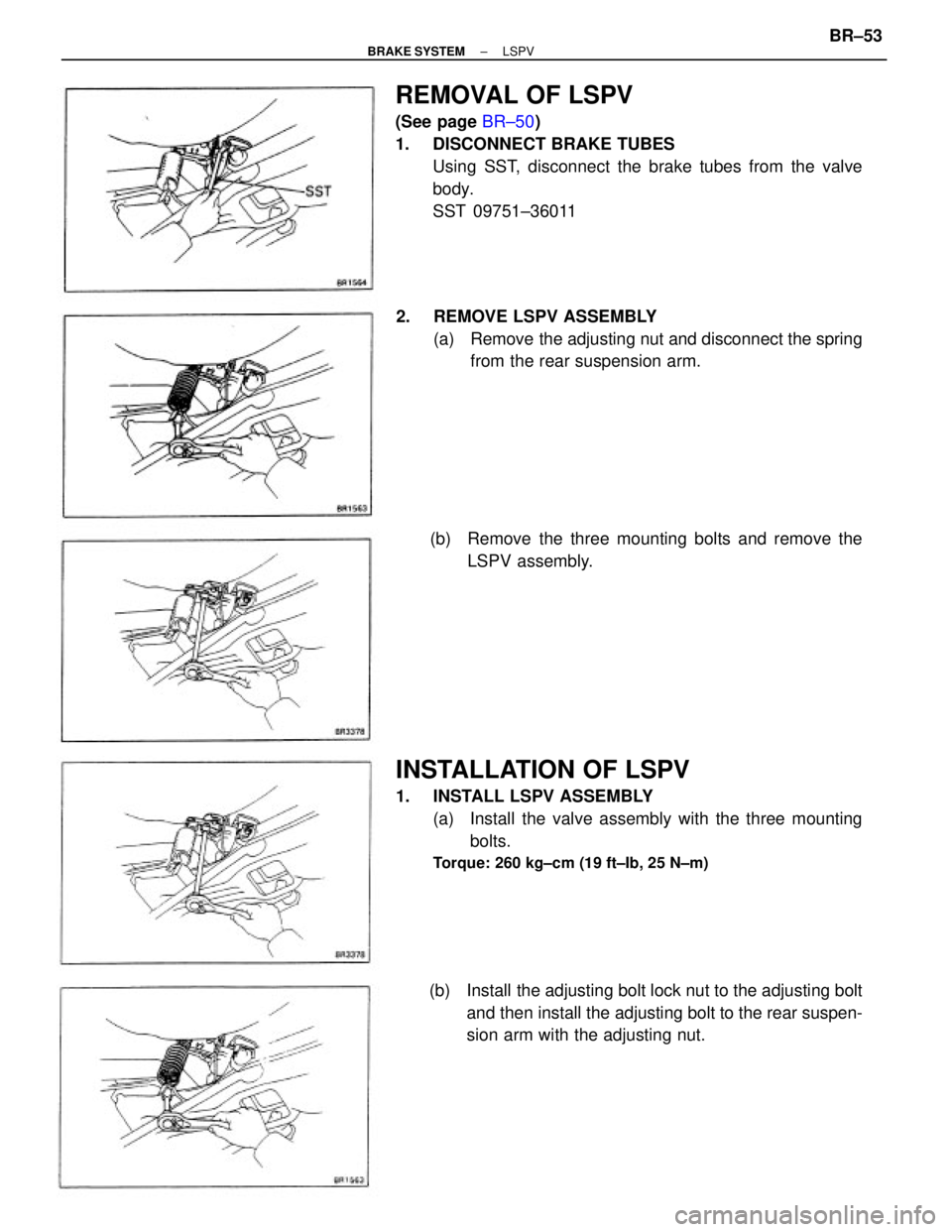
REMOVAL OF LSPV
(See page BR±50)
1. DISCONNECT BRAKE TUBES
Using SST, disconnect the brake tubes from the valve
body.
SST 09751±36011
INSTALLATION OF LSPV
1. INSTALL LSPV ASSEMBLY
(a) Install the valve assembly with the three mounting
bolts.
Torque: 260 kg±cm (19 ft±Ib, 25 N±m)
2. REMOVE LSPV ASSEMBLY
(a) Remove the adjusting nut and disconnect the spring
from the rear suspension arm.
(b) Install the adjusting bolt lock nut to the adjusting bolt
and then install the adjusting bolt to the rear suspen-
sion arm with the adjusting nut. (b) Remove the three mounting bolts and remove the
LSPV assembly.
± BRAKE SYSTEMLSPVBR±53
Page 905 of 2389
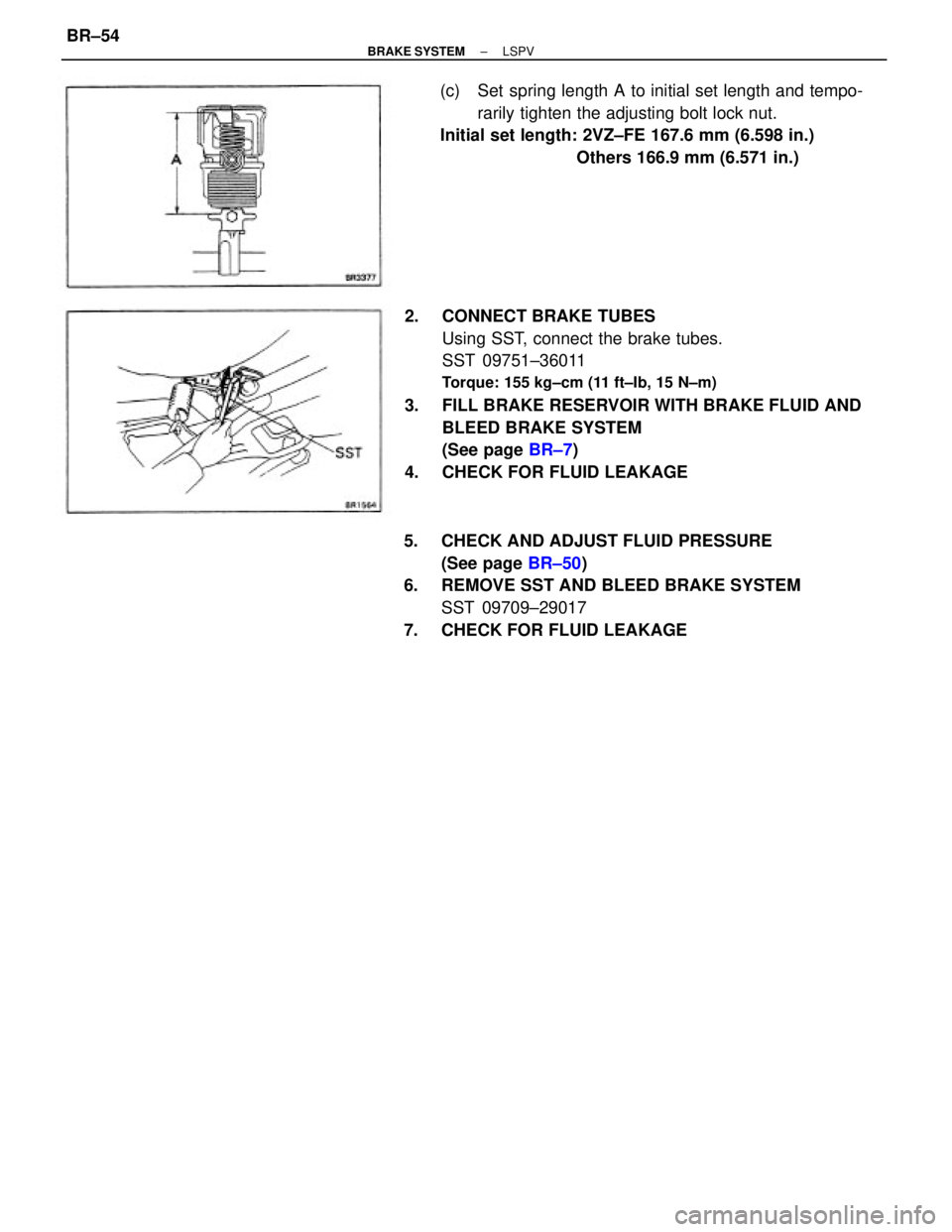
2. CONNECT BRAKE TUBES
Using SST, connect the brake tubes.
SST 09751±36011
Torque: 155 kg±cm (11 ft±Ib, 15 N±m)
3. FILL BRAKE RESERVOIR WITH BRAKE FLUID AND
BLEED BRAKE SYSTEM
(See page BR±7)
4. CHECK FOR FLUID LEAKAGE
5. CHECK AND ADJUST FLUID PRESSURE
(See page BR±50)
6. REMOVE SST AND BLEED BRAKE SYSTEM
SST 09709±29017
7. CHECK FOR FLUID LEAKAGE(c) Set spring length A to initial set length and tempo-
rarily tighten the adjusting bolt lock nut.
Initial set length: 2VZ±FE 167.6 mm (6.598 in.)
Others 166.9 mm (6.571 in.)
± BRAKE SYSTEMLSPVBR±54
Page 906 of 2389
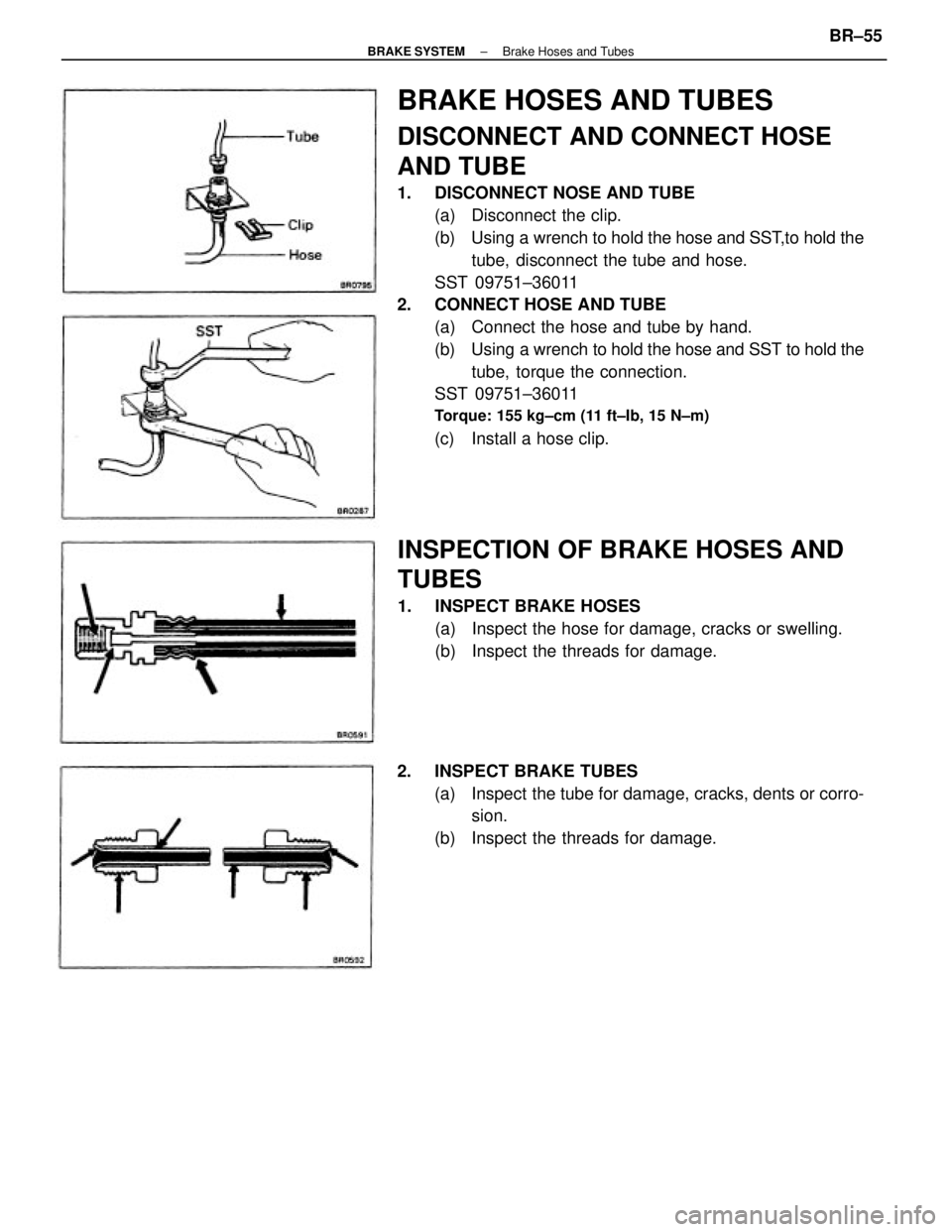
BRAKE HOSES AND TUBES
DISCONNECT AND CONNECT HOSE
AND TUBE
1. DISCONNECT NOSE AND TUBE
(a) Disconnect the clip.
(b) Using a wrench to hold the hose and SST,to hold the
tube, disconnect the tube and hose.
SST 09751±36011
2. CONNECT HOSE AND TUBE
(a) Connect the hose and tube by hand.
(b) Using a wrench to hold the hose and SST to hold the
tube, torque the connection.
SST 09751±36011
Torque: 155 kg±cm (11 ft±Ib, 15 N±m)
(c) Install a hose clip.
INSPECTION OF BRAKE HOSES AND
TUBES
1. INSPECT BRAKE HOSES
(a) Inspect the hose for damage, cracks or swelling.
(b) Inspect the threads for damage.
2. INSPECT BRAKE TUBES
(a) Inspect the tube for damage, cracks, dents or corro-
sion.
(b) Inspect the threads for damage.
± BRAKE SYSTEMBrake Hoses and TubesBR±55
Page 907 of 2389
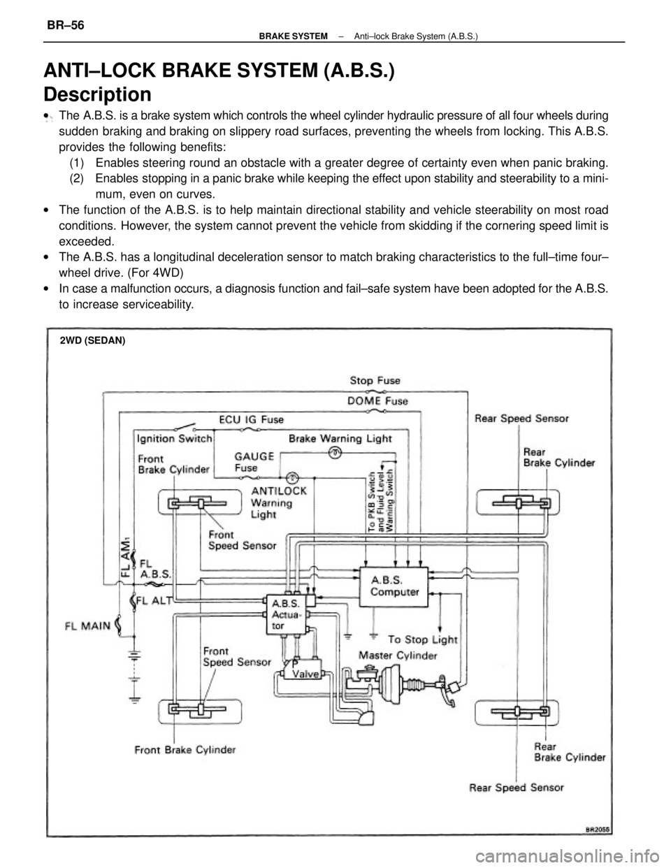
ANTI±LOCK BRAKE SYSTEM (A.B.S.)
Description
wThe A.B.S. is a brake system which controls the wheel cylinder hydraulic pressure of all four wheels during
sudden braking and braking on slippery road surfaces, preventing the wheels from locking. This A.B.S.
provides the following benefits:
(1) Enables steering round an obstacle with a greater degree of certainty even when panic braking.
(2) Enables stopping in a panic brake while keeping the effect upon stability and steerability to a mini-
mum, even on curves.
wThe function of the A.B.S. is to help maintain directional stability and vehicle steerability on most road
conditions. However, the system cannot prevent the vehicle from skidding if the cornering speed limit is
exceeded.
wThe A.B.S. has a longitudinal deceleration sensor to match braking characteristics to the full±time four±
wheel drive. (For 4WD)
wIn case a malfunction occurs, a diagnosis function and fail±safe system have been adopted for the A.B.S.
to increase serviceability.
2WD (SEDAN)
± BRAKE SYSTEMAnti±lock Brake System (A.B.S.)BR±56
Page 908 of 2389
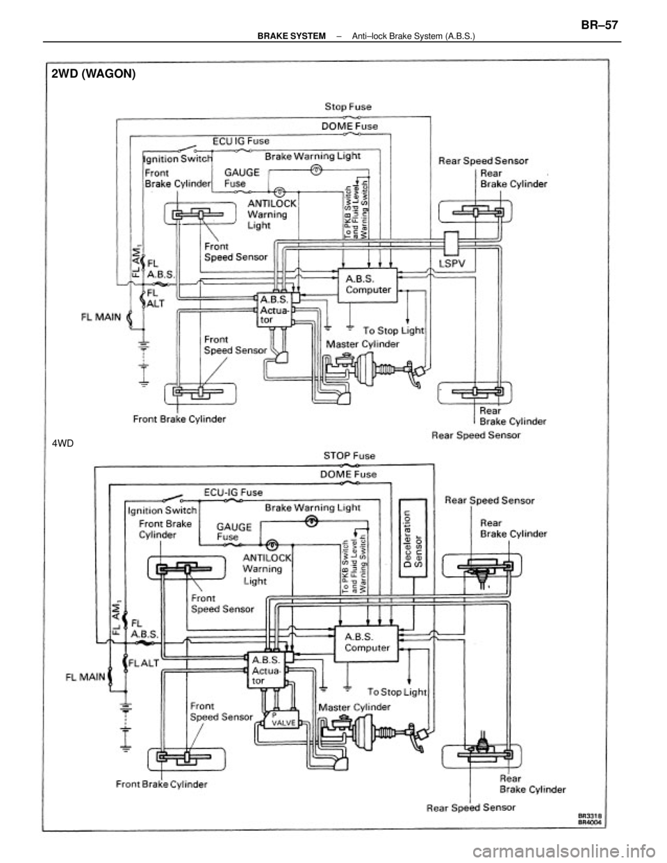
2WD (WAGON)
4WD
± BRAKE SYSTEMAnti±lock Brake System (A.B.S.)BR±57
Page 909 of 2389
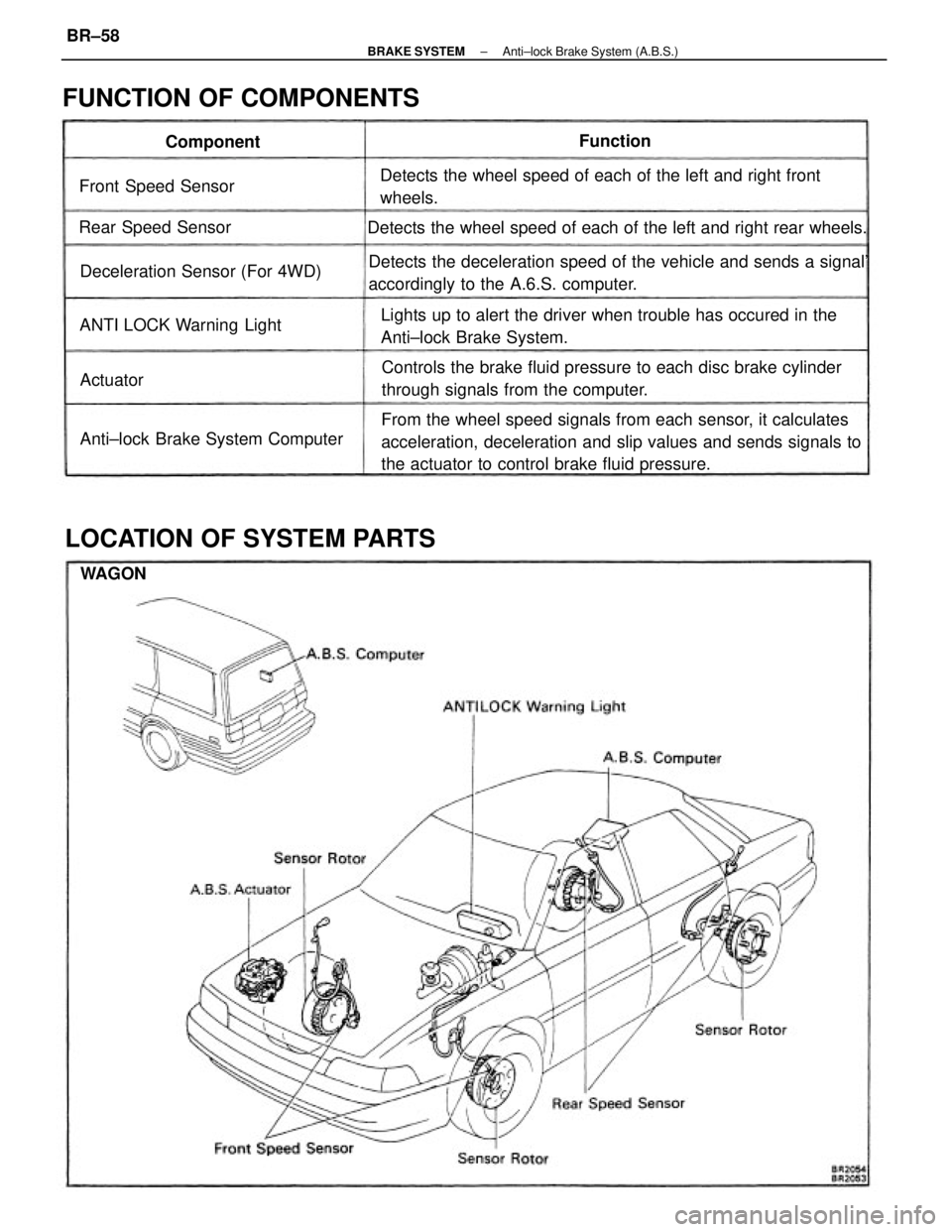
From the wheel speed signals from each sensor, it calculates
acceleration, deceleration and slip values and sends signals to
the actuator to control brake fluid pressure. Detects the deceleration speed of the vehicle and sends a signal'
accordingly to the A.6.S. computer.
Controls the brake fluid pressure to each disc brake cylinder
through signals from the computer. Lights up to alert the driver when trouble has occured in the
Anti±lock Brake System. Detects the wheel speed of each of the left and right front
wheels.
Detects the wheel speed of each of the left and right rear wheels.
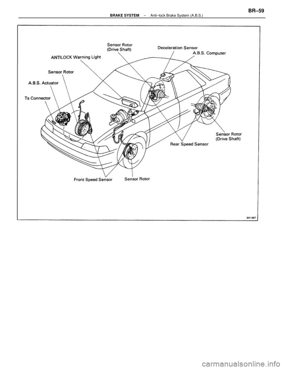
LOCATION OF SYSTEM PARTS FUNCTION OF COMPONENTS
Anti±lock Brake System Computer Deceleration Sensor (For 4WD)
ANTI LOCK Warning Light Front Speed Sensor
Rear Speed SensorComponentFunction
Actuator
WAGON
± BRAKE SYSTEMAnti±lock Brake System (A.B.S.)BR±58
Page 910 of 2389
± BRAKE SYSTEMAnti±lock Brake System (A.B.S.)BR±59
Trending: checking oil, set clock, check engine, air filter, wheel bolt torque, transmission, dead battery
