display TOYOTA MIRAI 2021 Accessories, Audio & Navigation (in English)
[x] Cancel search | Manufacturer: TOYOTA, Model Year: 2021, Model line: MIRAI, Model: TOYOTA MIRAI 2021Pages: 344, PDF Size: 12.08 MB
Page 224 of 344
2287-3. Panoramic view monitor
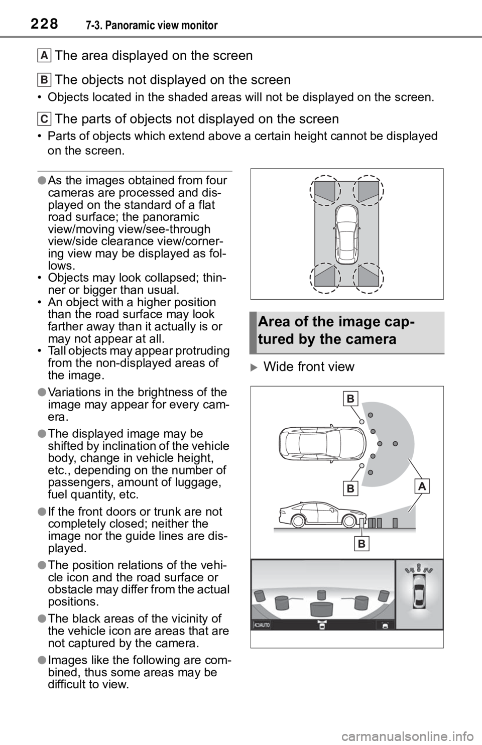
The area displayed on the screen
The objects not displayed on the screen
• Objects located in the shaded areas will not be displayed on t he screen.
The parts of objects not displayed on the screen
• Parts of objects which extend above a certain height cannot be displayed
on the screen.
●As the images obtained from four
cameras are processed and dis-
played on the standard of a flat
road surface; the panoramic
view/moving view/see-through
view/side clearance view/corner-
ing view may be displayed as fol-
lows.
• Objects may look collapsed; thin- ner or bigger than usual.
• An object with a higher position
than the road surface may look
farther away than i t actually is or
may not appear at all.
• Tall objects may appear protruding from the non-displayed areas of
the image.
●Variations in the brightness of the
image may appear for every cam-
era.
●The displayed image may be
shifted by inclination of the vehicle
body, change in vehicle height,
etc., depending on the number of
passengers, amou nt of luggage,
fuel quantity, etc.
●If the front doors or trunk are not
completely closed; neither the
image nor the guide lines are dis-
played.
●The position relations of the vehi-
cle icon and the road surface or
obstacle may differ from the actual
positions.
●The black areas of the vicinity of
the vehicle icon are areas that are
not captured by the camera.
●Images like the fo llowing are com-
bined, thus some areas may be
difficult to view.
Wide front view
A
B
C
Area of the image cap-
tured by the camera
Page 225 of 344
2297-3. Panoramic view monitor
7
Peripheral monitoring system
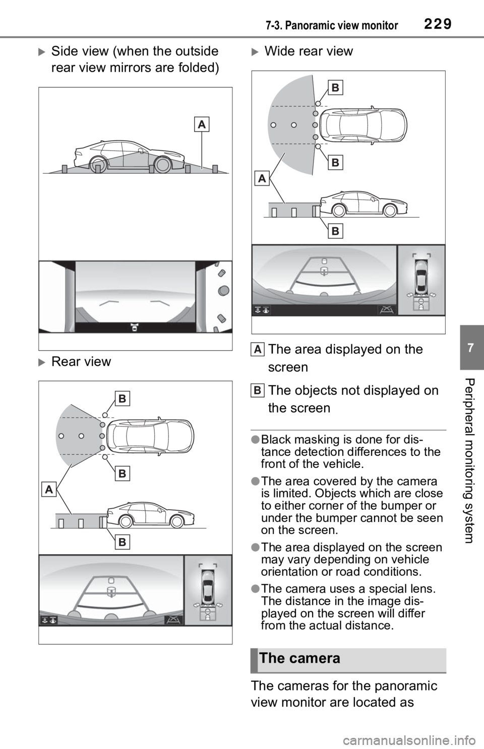
Side view (when the outside
rear view mirrors are folded)
Rear view
Wide rear viewThe area displayed on the
screen
The objects not displayed on
the screen
●Black masking is done for dis-
tance detection differences to the
front of the vehicle.
●The area covered by the camera
is limited. Objects which are close
to either corner of the bumper or
under the bumper cannot be seen
on the screen.
●The area displayed on the screen
may vary depending on vehicle
orientation or road conditions.
●The camera uses a special lens.
The distance in the image dis-
played on the screen will differ
from the actual distance.
The cameras for the panoramic
view monitor are located as
The camera
A
B
Page 228 of 344
2327-3. Panoramic view monitor
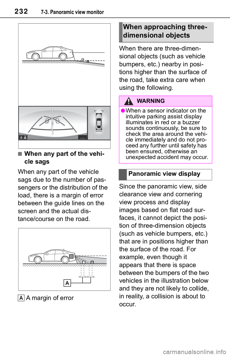
■When any part of the vehi-
cle sags
When any part of the vehicle
sags due to the number of pas-
sengers or the distribution of the
load, there is a margin of error
between the guide lines on the
screen and the actual dis-
tance/course on the road.
A margin of error When there are three-dimen-
sional objects (such as vehicle
bumpers, etc.) nearby in posi-
tions higher than the surface of
the road, take extra care when
using the following.
Since the panoramic view, side
clearance view and cornering
view process and display
images based on flat road sur-
faces, it cannot depict the posi-
tion of three-dimension objects
(such as vehicle bumpers, etc.)
that are in positions higher than
the surface of the road. For
example, even though it
appears that there is space
between the bumpers of the two
vehicles in the illustration below
and they are not likely to collide,
in reality, a collision is about to
occur.
A
When approaching three-
dimensional objects
WA R N I N G
●When a sensor indicator on the
intuitive parking assist display
illuminates in red or a buzzer
sounds continuously, be sure to
check the area around the vehi-
cle immediately and do not pro-
ceed any further until safety has
been ensured, otherwise an
unexpected accident may occur.
Panoramic view display
Page 229 of 344
2337-3. Panoramic view monitor
7
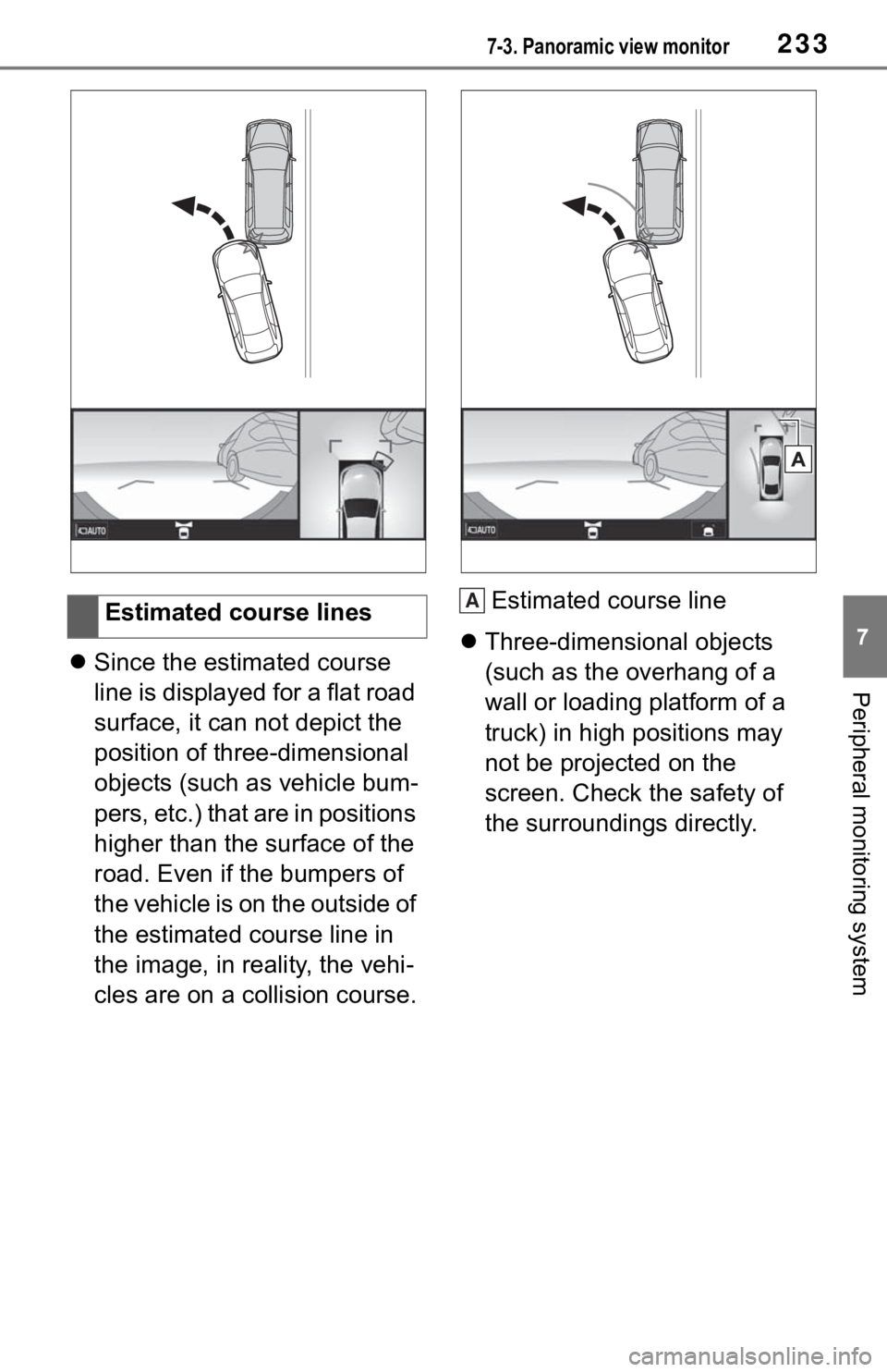
Peripheral monitoring systemSince the estimated course
line is displayed for a flat road
surface, it can not depict the
position of three-dimensional
objects (such as vehicle bum-
pers, etc.) that are in positions
higher than the surface of the
road. Even if the bumpers of
the vehicle is on the outside of
the estimated course line in
the image, in reality, the vehi-
cles are on a collision course. Estimated course line
Three-dimensional objects
(such as the overhang of a
wall or loading platform of a
truck) in high positions may
not be projected on the
screen. Check the safety of
the surroundings directly.
Estimated course lines
A
Page 233 of 344
2377-3. Panoramic view monitor
7
Peripheral monitoring system
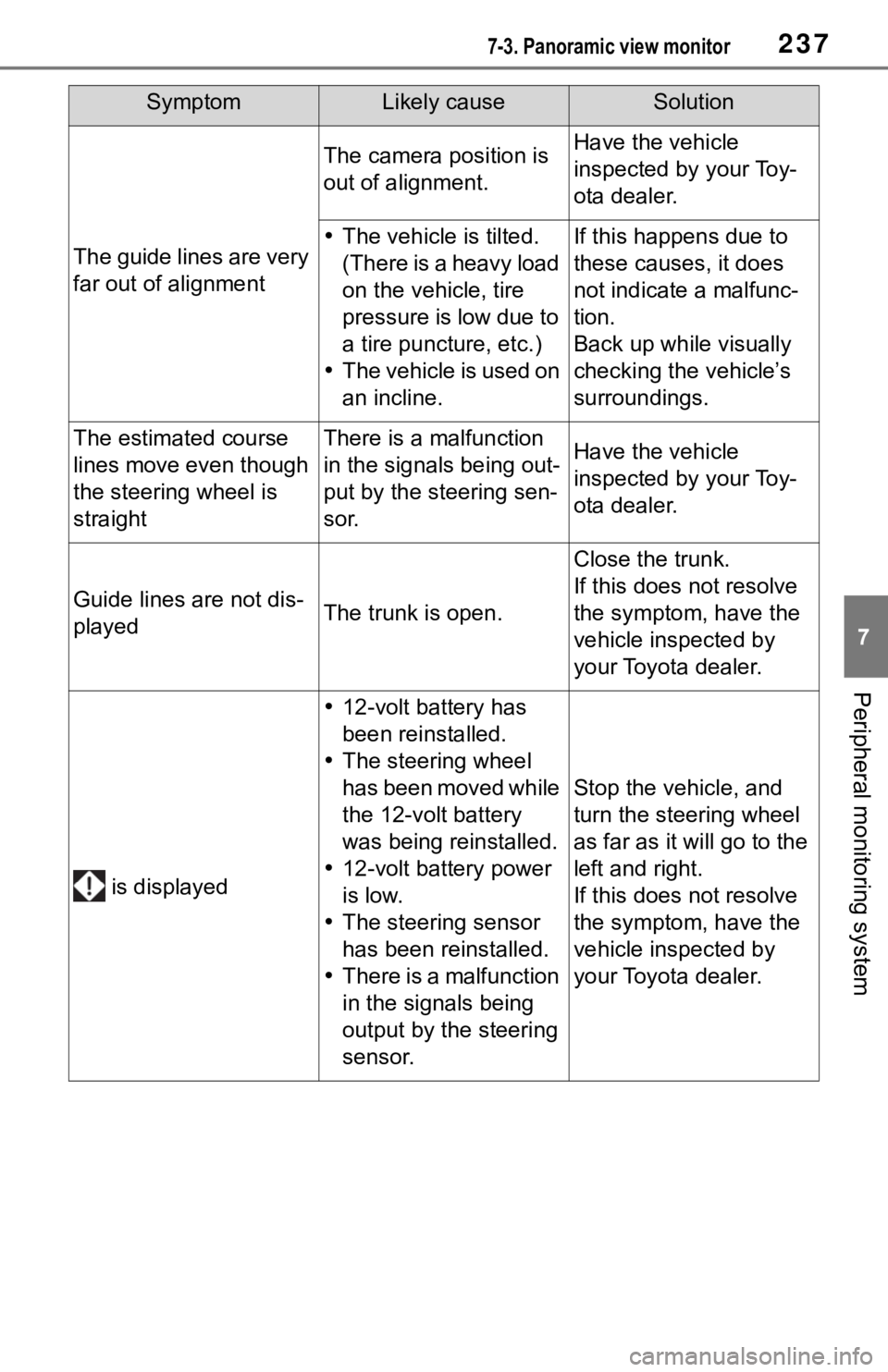
The guide lines are very
far out of alignment
The camera position is
out of alignment.Have the vehicle
inspected by your Toy-
ota dealer.
The vehicle is tilted.
(There is a heavy load
on the vehicle, tire
pressure is low due to
a tire puncture, etc.)
The vehicle is used on
an incline.If this happens due to
these causes, it does
not indicate a malfunc-
tion.
Back up while visually
checking the vehicle’s
surroundings.
The estimated course
lines move even though
the steering wheel is
straightThere is a malfunction
in the signals being out-
put by the steering sen-
sor.Have the vehicle
inspected by your Toy-
ota dealer.
Guide lines are not dis-
playedThe trunk is open.
Close the trunk.
If this does not resolve
the symptom, have the
vehicle inspected by
your Toyota dealer.
is displayed
12-volt battery has
been reinstalled.
The steering wheel
has been moved while
the 12-volt battery
was being reinstalled.
12-volt battery power
is low.
The steering sensor
has been reinstalled.
There is a malfunction
in the signals being
output by the steering
sensor.
Stop the vehicle, and
turn the steering wheel
as far as it will go to the
left and right.
If this does not resolve
the symptom, have the
vehicle inspected by
your Toyota dealer.
SymptomLikely causeSolution
Page 235 of 344
2397-4. Panoramic view monitor (vehicles with Toyota Teammate Advanced Park)
7
Peripheral monitoring system
7-4.Panoramic view monitor (vehicles with Toyota Teammate Advanced Park)
*: If equipped
●The screen illustrations used in
this text are intended as exam-
ples, and may differ from the
image that is actually displayed on
the screen.
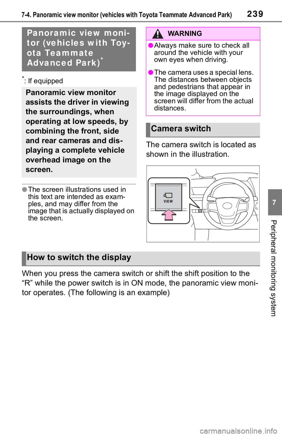
The camera switch is located as
shown in the illustration.
When you press the camera switch or shift the shift position to the
“R” while the power switch is in ON mode, the panoramic view mo ni-
tor operates. (The following is an example)
Panoramic view moni-
tor (vehicles with Toy-
ota Teammate
Advanced Park)
*
Panoramic view monitor
assists the driver in viewing
the surroundings, when
operating at low speeds, by
combining the front, side
and rear cameras and dis-
playing a complete vehicle
overhead image on the
screen.
WA R N I N G
●Always make sure to check all
around the vehicle with your
own eyes when driving.
●The camera uses a special lens.
The distances between objects
and pedestrians that appear in
the image displayed on the
screen will differ from the actual
distances.
Camera switch
How to switch the display
Page 236 of 344
2407-4. Panoramic view monitor (vehicles with Toyota Teammate Adva nced Park)
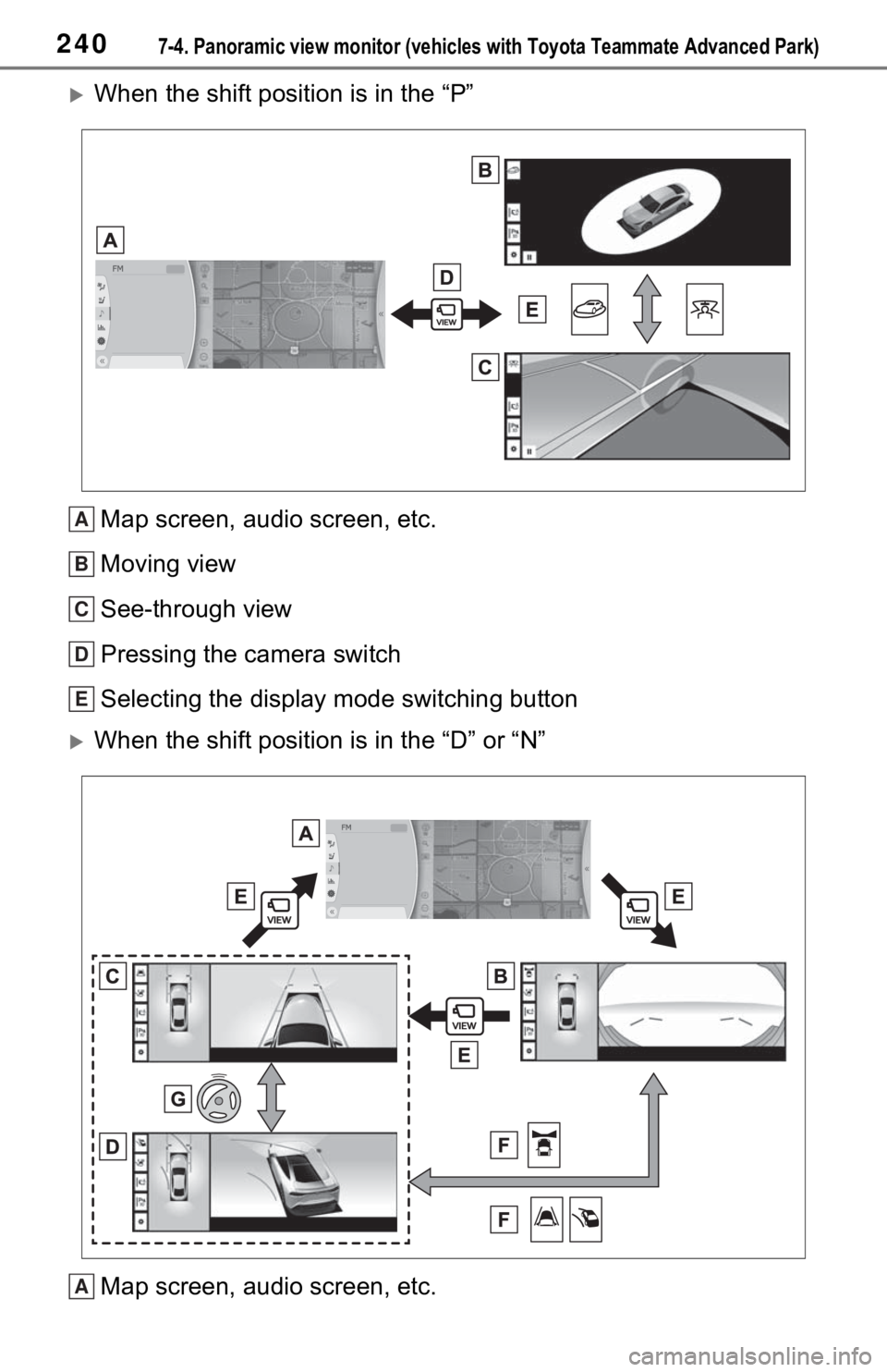
When the shift position is in the “P”
Map screen, audio screen, etc.
Moving view
See-through view
Pressing the camera switch
Selecting the display mode switching button
When the shift position is in the “D” or “N”
Map screen, audio screen, etc.
A
B
C
D
E
A
Page 237 of 344
2417-4. Panoramic view monitor (vehicles with Toyota Teammate Advanced Park)
7
Peripheral monitoring system
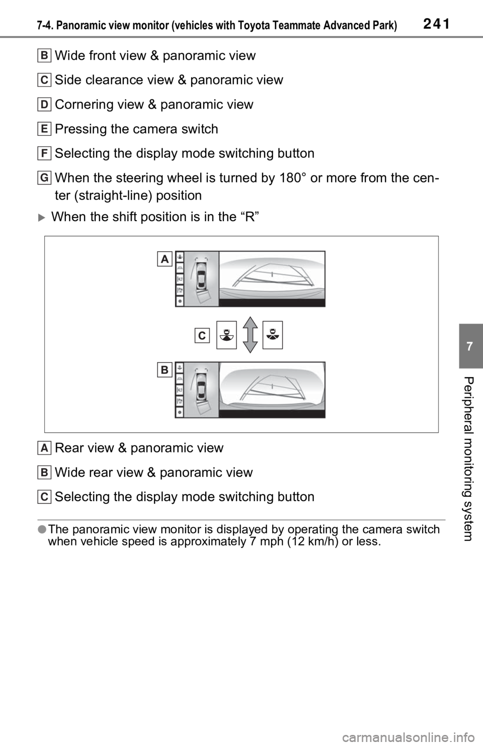
Wide front view & panoramic view
Side clearance view & panoramic view
Cornering view & panoramic view
Pressing the camera switch
Selecting the display mode switching button
When the steering wheel is turned by 180° or more from the cen-
ter (straight-line) position
When the shift position is in the “R”
Rear view & panoramic view
Wide rear view & panoramic view
Selecting the display mode switching button
●The panoramic view monitor is di splayed by operating the camera switch
when vehicle speed is approximately 7 mph (12 km/h) or less.
B
C
D
E
F
G
A
B
C
Page 238 of 344
2427-4. Panoramic view monitor (vehicles with Toyota Teammate Adva nced Park)
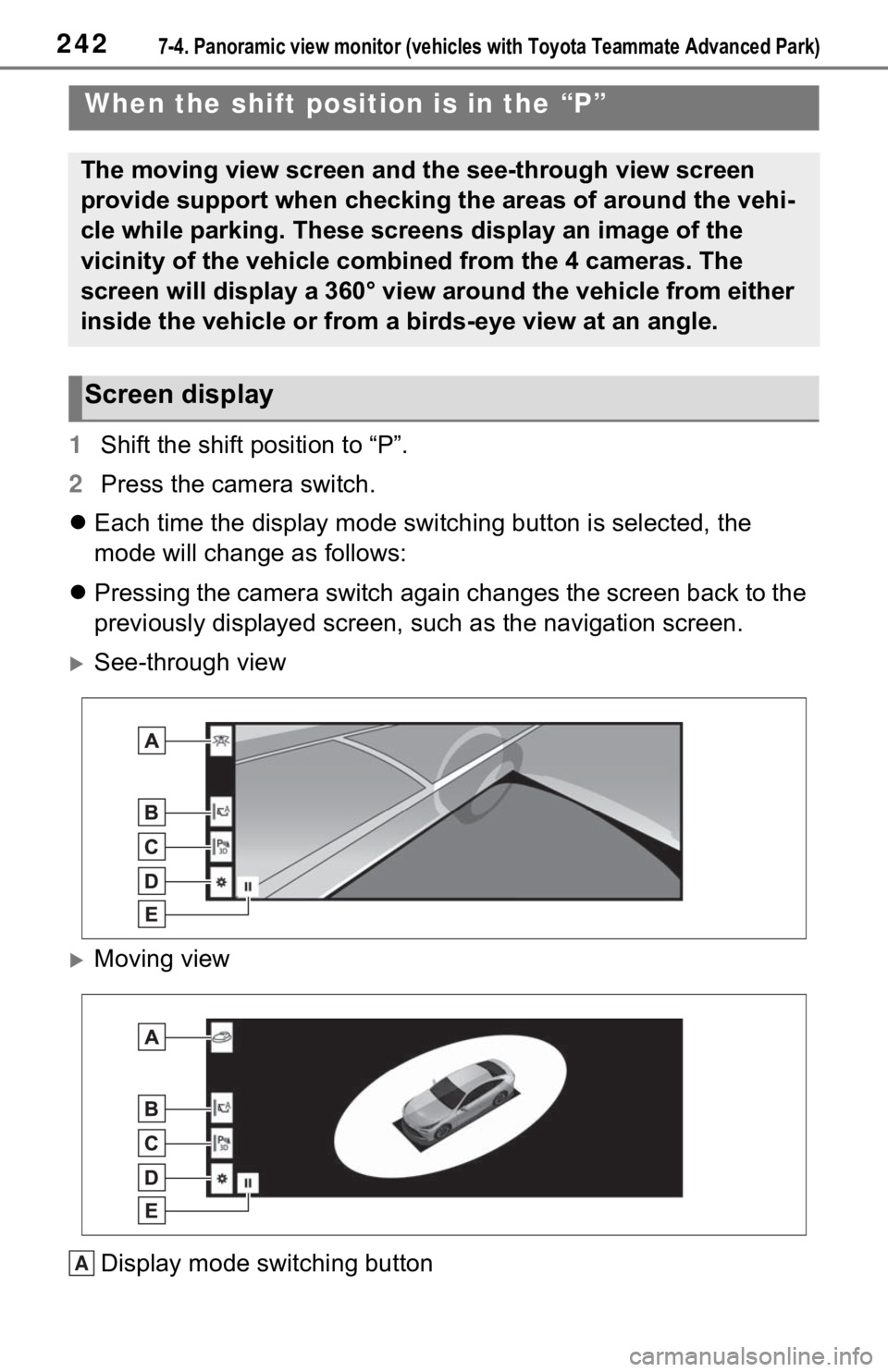
1Shift the shift position to “P”.
2 Press the camera switch.
Each time the display mode switching button is selected, the
mode will change as follows:
Pressing the camera switch again changes the screen back to the
previously displayed screen, such as the navigation screen.
See-through view
Moving view
Display mode switching button
When the shift position is in the “P”
The moving view screen and the see-through view screen
provide support when checking the areas of around the vehi-
cle while parking. These screens display an image of the
vicinity of the vehicle combined from the 4 cameras. The
screen will display a 360° view around the vehicle from either
inside the vehicle or from a birds-eye view at an angle.
Screen display
A
Page 239 of 344

2437-4. Panoramic view monitor (vehicles with Toyota Teammate Advanced Park)
7
Peripheral monitoring system
Select to change the display mode between the moving view and t he see-
through view.
Automatic display button
Select to turn automatic displ ay mode on/off. When the shift po sition is “D”
or “N”, the wide front view & pan oramic view or side clearance view & pan-
oramic view are automatically d isplayed according to the vehicle speed.
( P.248)
Intuitive parking assist 3D indicator button
Select to turn the int uitive parking assist indicator on/off. When the display
mode is ON, the intuitive parking assist indicator is displayed in 3D.
Customize settings button
Settings such as the cornering view automatic display mode, veh icle body
color on the screen and the detection distance of intuitive par king assist can
be changed. ( P.260)
Rotation pause/resume button
Select to pause/re sume the rotation of the screen.
●The see-through view screen and m oving view screen can be displayed
only when the intuitive parking assist is ON. For details about the intuitive
parking assist, refer to the “OWNER’S MANUAL”.
●The rotation display o f the see-through view/moving view screen can be
paused and resumed by selecting any place on the screen.
●A different screen is displayed w hen the Toyota Teammate Advanced Park
is activated. For details about t he Toyota Teammate Advanced Pa rk, refer
to the “OWNER’S MANUAL”.
B
C
D
E